
The demand for compact, high-performance reduction gearboxes has seen significant growth across advanced fields such as aerospace, medical robotics, and defense technology. These applications often impose stringent constraints on size, weight, and precision, necessitating the development of reducers that maintain high torque capacity and transmission accuracy within a minimal footprint. Among various precision reducers, the Rotary Vector reducer, commonly known as the RV reducer, is renowned for its high torsional stiffness, substantial load-bearing capacity, compact structure, and excellent motion control characteristics. However, commercially available RV reducers typically have a minimum outer diameter exceeding 100 mm, which limits their application in ultra-compact robotic joints or miniature mechanical systems. This paper addresses this gap by proposing the design and comprehensive analysis of a small-sized Rotary Vector reducer with a maximum radial dimension under 70 mm. The work encompasses structural parameter determination, static force analysis, theoretical strength verification, and validation through finite element simulation.
The primary challenge in miniaturizing the Rotary Vector reducer lies in maintaining its advantageous performance characteristics—namely, high reduction ratio, load capacity, and stiffness—while drastically reducing its geometric scale. This requires a meticulous redesign of its two-stage reduction mechanism. The conventional RV transmission integrates a first-stage planetary gear train with a second-stage cycloidal-pin gear mechanism. Scaling down this complex system involves novel approaches to component design, bearing selection, and parameter optimization to prevent interference and ensure structural integrity under load.
Structural Composition and Operating Principle
The proposed compact Rotary Vector reducer retains the fundamental two-stage architecture of its larger counterparts but implements key modifications for size reduction. The core transmission system consists of a first-stage involute planetary gear set and a second-stage cycloid drive with a single tooth difference. The power flow and force transmission within this compact system form a closed loop, which is crucial for its high stiffness and compactness.
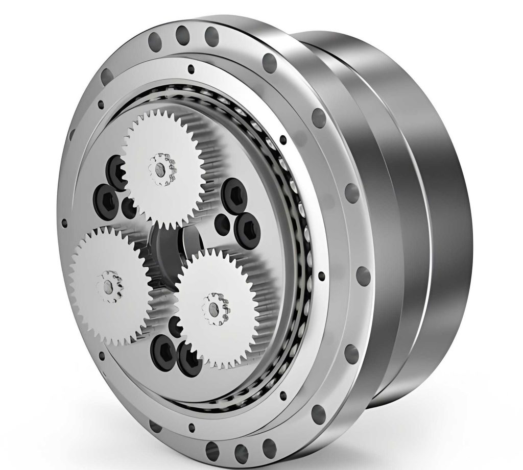
The kinematic chain operates as follows: An input motor drives the central sun gear. This sun gear meshes with multiple planetary gears (typically two or three for balance), achieving the first stage of speed reduction and torque amplification. The planetary gears are mounted on eccentric shafts. As the planetary gears rotate, they cause the eccentric shafts to revolve around the central axis (a motion termed “revolution” or “public rotation”). Each eccentric shaft carries a cycloid gear via a compact bearing. The eccentric motion of the shaft forces the cycloid gear to engage with a ring of stationary pin gears housed in a fixed pin housing. This engagement causes the cycloid gear to rotate on its own axis (“private rotation”) at a reduced speed. This private rotation is then transmitted through pins (or a similar mechanism like a crank) to the output flange. A critical aspect of the Rotary Vector reducer’s operation is the feedback of the output motion into the first stage. The rotation of the output flange is fed back to the planetary gear carrier, creating a differential effect and resulting in the final, high reduction ratio output at the flange. The closed-loop power transmission is summarized by the following kinematic relationship, where $n_i$, $n_o$, and $n_c$ represent the speeds of the input sun gear, output flange, and planetary carrier, respectively, and $z_s$, $z_p$, $z_c$, $z_p$ denote the number of teeth on the sun, planet, cycloid, and pin gear:
$$ i_{RV} = \frac{n_i}{n_o} = 1 + \frac{z_p}{z_s} \times \frac{z_p}{z_p – z_c} $$
For the designed compact Rotary Vector reducer, with $z_s=15$, $z_p=30$, $z_c=29$, and $z_p=30$, the theoretical reduction ratio is:
$$ i_{RV} = 1 + \frac{30}{15} \times \frac{30}{30-29} = 1 + 2 \times 30 = 61 $$
Determination of Key Geometric Parameters
The design process begins with establishing the fundamental geometric constraints for both reduction stages to ensure functionality, avoid interference, and achieve the target size and ratio.
First-Stage Involute Planetary Gear Design
The planetary stage must provide a substantial portion of the total reduction ratio while fitting within the radial envelope defined by the second-stage cycloid drive. The primary constraints and design decisions are:
- Gear Ratio and Size: To manage torque levels in the first stage and ensure balanced load sharing among planets, the planet-to-sun gear ratio should satisfy $z_p / z_s \ge 1.5$. For compactness and manufacturability of small gears, the sun gear tooth count is limited to $9 \le z_s \le 20$.
- Radial Compatibility: The center distance $a$ of the planetary stage must be proportional to the pin gear distribution circle radius $r_p$ of the cycloid stage to maintain a balanced and compact radial layout: $a = (0.5 \sim 0.6) r_p$. Furthermore, the overall radial dimension of the planetary gear set should align with that of the cycloid stage: $m(z_s/2 + z_p) = (0.9 \sim 1.1) r_p$, where $m$ is the module.
- Planet Interference: For $n_w$ equally spaced planetary gears, their tip diameters $d_{a2}$ must not interfere: $d_{a2} < 2a \sin(\pi / n_w)$.
- Tooth Modification: Due to the low tooth counts, profile shifting (modification) is essential to avoid undercutting, improve strength, and balance specific sliding coefficients for similar wear life. A high-correction design is adopted. The sum of modification coefficients $x_{\Sigma} = x_s + x_p = 0$, but $x_s > 0$ and $x_p < 0$. The values are chosen to equalize the maximum specific sliding coefficients $\eta_{1max}$ and $\eta_{2max}$ at the sun and planet gear teeth roots.
$$ \eta_{1max} = \frac{ \tan\alpha_{a2} – \tan\alpha’ }{ (1 + z_s/z_p) \tan\alpha’ – \tan\alpha_{a2} } \cdot \frac{u+1}{u} $$
$$ \eta_{2max} = \frac{ \tan\alpha_{a1} – \tan\alpha’ }{ (1 + z_p/z_s) \tan\alpha’ – \tan\alpha_{a1} } \cdot (u+1) $$
where $\alpha’$ is the operating pressure angle, $\alpha_{a1}, \alpha_{a2}$ are the tip pressure angles, and $u = z_p/z_s$.
Based on these constraints and targeting an overall ratio of 61, the parameters were selected as shown in the table below. A small module of 0.5 mm was chosen to fit the required teeth within the limited center distance.
| Parameter | Symbol | Value |
|---|---|---|
| Module | $m$ | 0.5 mm |
| Sun Gear Teeth | $z_s$ | 15 |
| Planet Gear Teeth | $z_p$ | 30 |
| Pressure Angle | $\alpha$ | 20° |
| Sun Gear Modification Coeff. | $x_s$ | +0.34 |
| Planet Gear Modification Coeff. | $x_p$ | -0.34 |
| Center Distance | $a$ | 11.25 mm |
| Contact Ratio | $\epsilon_{\alpha}$ | 1.512 |
Second-Stage Cycloid-Pin Gear Design
The cycloid drive provides the primary reduction and is central to the compact Rotary Vector reducer’s high torque density. Its design is governed by specific geometric relationships to ensure proper meshing and avoid tooth undercutting.
- Pin Circle Radius: This is a primary size driver. An empirical relation $r_p \approx (10 \sim 13)\sqrt[3]{T_o}$ can be used, where $T_o$ is the output torque. For our compact design, $r_p$ was set to 20 mm based on the overall size target of φ70 mm.
- Tooth Difference and Reduction: The reduction ratio of the cycloid stage is $i_c = z_p / (z_p – z_c)$. A single tooth difference ($z_p – z_c = 1$) is standard for high ratios, giving $i_c = z_p$. With $z_p=30$, this contributes significantly to the total ratio.
- Shortening Coefficient: The shortening coefficient $K_1 = e z_p / r_p$ (where $e$ is eccentricity) determines the shape of the cycloid profile. For standard designs, $0.5 < K_1 < 1$. A value of $K_1=0.675$ was chosen to optimize contact stress and mechanical advantage.
- Undercutting Prevention: The theoretical cycloid profile must have a minimum curvature radius $\rho_{0min}$ greater than the pin radius $r_{rp}$ to prevent undercutting or pointed teeth. The minimum curvature radius coefficient $a_{min}$ is given by:
$$ a_{min} = \frac{27 z_c^3 (1 – K_1^2)}{(z_c + 2)^3} $$
The condition is $\rho_{0min} = r_p a_{min} > r_{rp}$. - Pin Diameter Coefficient: The pin radius is selected based on the pin diameter coefficient $K_2 = \frac{r_p \sin(\pi / z_p)}{r_{rp}}$, typically between 1.5 and 2.0, to ensure adequate pin housing strength and avoid overcrowding.
The final key geometric parameters for the compact Rotary Vector reducer’s cycloid stage are:
| Parameter | Symbol | Value |
|---|---|---|
| Pin Distribution Circle Radius | $r_p$ | 20.0 mm |
| Pin Radius | $r_{rp}$ | 1.3 mm |
| Number of Pins | $z_p$ | 30 |
| Number of Cycloid Teeth | $z_c$ | 29 |
| Eccentricity | $e$ | 0.45 mm |
| Shortening Coefficient | $K_1$ | 0.675 |
| Pin Diameter Coefficient | $K_2$ | 1.608 |
Output Mechanism and Bearing Selection
The output mechanism transmits the rotation of the cycloid gear to the output flange. In this compact Rotary Vector reducer design, a pin-in-hole mechanism (also known as a crank or wobble mechanism) is employed. The output pins on the flange engage with holes in the cycloid gear. The diameter relationship is critical: $d_w = d_{gw} – 2e$, where $d_w$ is the pin diameter, $d_{gw}$ is the hole diameter, and $e$ is the eccentricity. Furthermore, the wall thickness between adjacent holes and between the holes and the cycloid gear’s inner bore must be checked to ensure structural integrity, typically requiring $\delta \ge 0.03 r_p$.
Bearing selection is a significant challenge in miniaturization. Standard RV reducer bearings are too large. For this compact Rotary Vector reducer, miniature precision bearings (e.g., MR95zz, MR104zz) are specified for the crankshaft (rotating between the eccentric shaft and cycloid gear) and support bearings. Their inclusion dictates that the cycloid gear width matches the bearing width, a slight departure from designs where the gear bore acts as the bearing outer race.
Force Analysis and Theoretical Strength Verification
To ensure the reliability of the compact Rotary Vector reducer, a static force analysis and theoretical strength check were performed for both transmission stages. The input power is $P=0.15$ kW, target output speed is $n_o=15$ rpm, and the total theoretical efficiency $\eta$ was estimated at 0.929, yielding an output torque $T_o \approx 88.75$ N·m.
Force Analysis of the Planetary Gear Stage
Ignoring friction, the forces between meshing sun and planet gears are tangential ($F_t$) and radial ($F_r$). For a system with $n_w$ planets, the tangential force on a single planet from the sun gear is:
$$ F_{t21} = \frac{2 T_{in}}{n_w d_s} $$
where $T_{in}$ is the input torque at the sun gear and $d_s$ is the sun gear’s reference diameter. The radial force is $F_{r21} = F_{t21} \tan\alpha’$. By Newton’s third law, $F_{t12} = -F_{t21}$ and $F_{r12} = -F_{r21}$.
For the designed compact Rotary Vector reducer with $n_w=3$, the calculated forces are:
| Component | Tangential Force $F_t$ (N) | Radial Force $F_r$ (N) |
|---|---|---|
| Sun Gear | -208.74 | -75.98 |
| Planet Gear | +208.74 | +75.98 |
Force Analysis of the Cycloid-Pin Stage
The force analysis for the cycloid gear is more complex due to multiple simultaneous contact points. The forces include the resultant of contact forces from the pins ($\sum \vec{F}_i$) and the reaction forces from the crankshaft bearings ($\vec{F}_{34}, \vec{F}_{3’4}$). Under equilibrium, the sums of forces in the x and y directions and the sum of moments must be zero. The moment equilibrium gives the total tangential component of pin forces. Research shows that the distribution of force among the contacting pins is not uniform. The maximum force $F_{max}$ on a single pin occurs when the contact line is perpendicular to the eccentric direction and can be approximated by:
$$ F_{max} = \frac{2.2 T_o}{r_p K_1 z_c} $$
This formula accounts for an uneven load distribution factor (using 0.55 of total torque per cycloid gear in a two-gear system) and the specific geometry of the compact Rotary Vector reducer. Substituting values ($T_o=88.75$ N·m, $r_p=20$ mm, $K_1=0.675$, $z_c=29$):
$$ F_{max} = \frac{2.2 \times 88.75}{0.020 \times 0.675 \times 29} \approx 498.7 \text{ N} $$
Theoretical Strength Verification
Material selection is critical for the compact Rotary Vector reducer. The gears were assigned material properties as follows:
- Involute Gears: 20CrMnTi (Case-hardened steel). Yield strength $\sigma_s \approx 850$ MPa, allowable contact stress $[\sigma_H] \approx 1260$ MPa, allowable bending stress $[\sigma_F] \approx 720$ MPa.
- Cycloid Gear & Pins: GCr15 (Bearing steel). Allowable contact stress $[\sigma_H] \approx 1300$ MPa.
1. Involute Gear Strength:
Bending stress $\sigma_F$ and contact stress $\sigma_H$ were calculated using standard AGMA-inspired formulas for small module gears with profile shift.
Bending Stress:
$$ \sigma_F = \frac{K_F F_t Y_{Fa} Y_{Sa} Y_{\epsilon}}{m b} $$
Where $K_F$ is the load factor, $Y_{Fa}$ the tooth form factor, $Y_{Sa}$ the stress correction factor, $Y_{\epsilon}$ the contact ratio factor, and $b$ the face width.
Contact Stress:
$$ \sigma_H = \sqrt{ \frac{2 K_H T_1}{b d_s^2} \cdot \frac{u+1}{u} } \cdot Z_H Z_E Z_{\epsilon} $$
Where $K_H$ is the contact load factor, $Z_H$ the zone factor, $Z_E$ the elasticity factor, and $Z_{\epsilon}$ the contact ratio factor.
The calculated stresses were:
| Component | Bending Stress $\sigma_F$ (MPa) | Contact Stress $\sigma_H$ (MPa) |
|---|---|---|
| Sun Gear | 697.8 | 664.9 |
| Planet Gear | 667.5 | 664.9 |
Both $\sigma_F$ and $\sigma_H$ are below their respective allowable limits, verifying the planetary stage’s theoretical strength.
2. Cycloid-Pin Contact Strength:
The contact between a cylindrical pin and the curved cycloid tooth flank is modeled as contact between two cylinders. The maximum Hertzian contact stress $\sigma_{H2}$ is:
$$ \sigma_{H2} = 0.418 \sqrt{ \frac{F_{max}}{B} \cdot \frac{1}{\rho_d} \cdot \frac{2 E_1 E_2}{E_1 + E_2} } $$
where $B$ is the cycloid gear width, $E_1, E_2$ are the elastic moduli (206 GPa for GCr15), and $\frac{1}{\rho_d}$ is the relative curvature. The curvature $\rho$ of the cycloid profile at the point of maximum force is complex but can be derived from its parametric equations. For a pin at the position of $F_{max}$, the relative curvature is approximately:
$$ \frac{1}{\rho_d} = \frac{1}{r_{rp}} – \frac{1}{\rho} \approx \frac{1}{r_{rp}} + \frac{1}{r_p K_1 (1 – \frac{1}{K_1^2})} $$
A more precise calculation using the derived geometry yields a theoretical maximum contact stress of:
$$ \sigma_{H2 (theory)} \approx 263.8 \text{ MPa} $$
This is well below the allowable 1300 MPa for GCr15, confirming the cycloid stage’s sufficient contact strength in theory.
Finite Element Simulation and Validation
To validate the theoretical design and analysis of the compact Rotary Vector reducer, detailed Finite Element Analysis (FEA) was conducted using ANSYS Workbench. The goal was to simulate the stress state under load and compare it with theoretical predictions.
Simulation of the Involute Planetary Stage
A static structural analysis was performed on a sun-planet gear pair model. Key steps included:
- Material Assignment: 20CrMnTi with $E=207$ GPa, $\nu=0.254$.
- Contact Definition: Frictional contact (coefficient 0.1) between tooth flanks.
- Boundary Conditions: The sun gear’s hub was coupled to a remote point where the input torque ($T_{in}=782.8$ Nmm) was applied. The planet gear’s hub was constrained to rotate only about its axis. The sun gear’s axis was also fixed in rotation except about its own axis.
- Meshing: A fine tetrahedral mesh with local refinement at the contact regions.
The FEA results for the compact Rotary Vector reducer’s planetary stage were:
- Maximum Total Deformation: 0.126 mm
- Maximum Equivalent (von Mises) Stress: 693.0 MPa
- Maximum Contact Stress (on tooth flank): 703.3 MPa
The location of maximum bending stress was at the tooth root fillet, and maximum contact stress was at the pitch line region, conforming to theory.
Simulation of the Cycloid-Pin Stage
A sub-model of the cycloid gear engaging with a segment of the pin housing (modeled as a rigid ring with cylindrical pin seats) was analyzed.
- Material Assignment: GCr15 for cycloid gear ($E=206$ GPa, $\nu=0.3$).
- Contact Definition: Frictionless contact between cycloid tooth flanks and cylindrical pin surfaces.
- Boundary Conditions: The pin housing was fixed. A cylindrical support on the cycloid gear’s inner bore allowed rotation only. A torque of $T_g = 0.55 T_o / 2 \approx 1479.7$ Nmm was applied to the inner bore surface to simulate the load from one eccentric shaft.
- Meshing: A hex-dominant mesh with high refinement in the contact zones.
The FEA results for the compact Rotary Vector reducer’s cycloid stage were:
- Maximum Total Deformation: 0.00121 mm (indicating high stiffness)
- Maximum Equivalent Stress: 276.7 MPa
- Maximum Contact Stress: 234.7 MPa
The stress was concentrated on the cycloid tooth flanks near the region theoretically predicted for maximum load.
Comparison and Discussion
The comparison between theoretical calculations and FEA simulation results for the critical contact stresses is summarized below. The agreement validates the design methodology for the compact Rotary Vector reducer.
| Component | FEA Result $\sigma_H$ (MPa) | Theoretical Result $\sigma_H$ (MPa) | Allowable Stress $[\sigma_H]$ (MPa) | Error |
|---|---|---|---|---|
| Involute Gears | 703.3 | 664.9 | 1260 | +5.77% |
| Cycloid-Pin | 234.7 | 263.8 | 1300 | -11.03% |
The discrepancies are within an acceptable range for engineering design and can be attributed to several factors: simplifications in theoretical force distribution models (especially for the cycloid drive), idealizations in the Hertzian contact formula for non-standard curvatures, and the finite element model’s discretization and boundary condition approximations. Importantly, both FEA results are significantly lower than the materials’ allowable stresses, confirming a substantial safety margin and the fundamental robustness of the compact Rotary Vector reducer design.
Conclusion
This work presents a complete design and analysis framework for a novel compact Rotary Vector reducer with an outer diameter under 70 mm. The design successfully reconciles the conflicting demands of miniaturization and high performance by meticulously determining geometric parameters for both the planetary and cycloid stages, incorporating miniature bearings, and adhering to strict mechanical design constraints to prevent interference. Theoretical force analysis and strength verification based on standard mechanical design principles confirmed the feasibility of the component dimensions. Subsequent detailed finite element simulations provided strong correlation with theoretical stress predictions, with maximum contact stress errors of 5.77% for the involute gears and 11.03% for the cycloid-pin interface. This close agreement validates the correctness of the analytical models and the structural rationality of the proposed compact Rotary Vector reducer. The methodology and results established in this study offer a solid theoretical foundation and a practical reference for the further development, optimization, and eventual prototyping of small-sized and micro Rotary Vector reducers for advanced precision applications.