
Abstract In the realm of robot technology, addressing the obstacle-surmounting limitations of traditional wheeled robots is crucial for enhancing mobility in complex environments. This paper presents a novel single-degree-of-freedom composite link leg structure for wheel-leg hybrid robots. Through kinematic modeling, trajectory planning, and optimization algorithms, the research aims to improve both locomotion efficiency and obstacle-crossing capabilities, contributing to advancements in robot technology.
Keywords: robot technology; wheel-leg hybrid robot; foot trajectory planning; particle swarm optimization; kinematic simulation
1. Introduction
The development of robot technology has significantly advanced mobile robots’ capabilities across various industries. Wheeled robots offer high efficiency on flat terrains but struggle with obstacles, while legged robots excel in rugged environments but lack speed. Wheel-leg hybrid robots, a subset of robot technology, combine the advantages of both, making them a promising direction in mobile robot research.
1.1 Research Background
In robot technology, numerous studies have focused on wheel-leg hybrid designs. For example, Japan’s Chiba Institute of Technology developed the 8-legged Halluc-II with 4 DOF per leg, though its high motor count (56) complicates control. Caltech’s ATHLETE robot, with 6 DOF per leg and wheeled endpoints, demonstrates effective obstacle negotiation but requires complex mechanics. Chinese institutions like Harbin Institute of Technology and Chongqing University have also contributed designs, highlighting the global interest in this sector of robot technology.
1.2 Research Objectives
This study targets the limitations of existing designs—complex structures, high control difficulty, and insufficient obstacle capability. By introducing a single-DOF composite link leg structure, we aim to simplify control while enhancing performance. The innovative pairing of two single legs into a wheel-leg module ensures both efficiency and adaptability, pushing the boundaries of robot technology.
2. Robot Structure and Kinematic Analysis of Leg Mechanism
2.1 Robot Structure Design
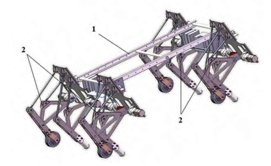
The proposed wheel-leg hybrid robot features a quadruped design, comprising a body frame, mounting plates, and four identical leg modules (Figure 1). Each module integrates two single-DOF legs: one with a wheel (hub motor) for wheeled motion on flat surfaces and the other for legged locomotion over obstacles. This dual-mode design optimizes efficiency and adaptability, a key innovation in robot technology.
Table 1. Robot Structure Components
| Component | Function |
|---|---|
| Body Frame | Houses motor drivers and lithium batteries |
| Mounting Plate | Connects legs to the frame at a fixed angle |
| Leg Module | Combines wheeled and legged mechanisms for dual-mode locomotion |
| Hub Motor | Drives wheeled motion; locks for legged mode during obstacle negotiation |
2.2 Kinematic Analysis of Single Leg Mechanism
The single leg is a six-bar mechanism with 5 moving parts, 7 lower pairs, and 0 higher pairs. Using the Gruebler-Kutzbach formula:\(F = 3n – (2P_L + P_H) = 3 \times 5 – (2 \times 7 + 0) = 1\) This confirms a single degree of freedom, simplifying control—a critical aspect in robot technology for practical implementation.
2.2.1 Vector-Based Kinematic Modeling
Using a local coordinate system (origin at point A), we derive closed-vector equations for the crank-rocker mechanism:\(\begin{cases} l_1 \cos \theta_1 + l_2 \cos \theta_2 = l_4 + l_3 \cos \theta_3 \\ l_1 \sin \theta_1 + l_2 \sin \theta_2 = l_3 \sin \theta_3 \end{cases}\) Eliminating \(\theta_2\) yields:\(a \sin \theta_3 + b \cos \theta_3 + c = 0\) where \(a = 2l_1l_3 \sin \theta_1\), \(b = 2l_3(l_1 \cos \theta_1 – l_4)\), \(c = l_2^2 – l_1^2 – l_3^2 – l_4^2 + 2l_1l_4 \cos \theta_1\).
Solving for \(\theta_3\) and \(\theta_2\) using trigonometric identities, we derive coordinates for key points (G, E, H) and transform them to the global coordinate system:\(\begin{cases} X_H = x_H \cos \theta_0 – y_H \sin \theta_0 \\ Y_H = x_H \sin \theta_0 + y_H \cos \theta_0 \end{cases}\) These equations form the basis for trajectory planning, a fundamental component of robot technology.
3. Parameter Optimization of Leg Structure
3.1 Ideal Foot Trajectory Planning
In robot technology, smooth trajectories are vital for stability. We select an elliptic curve for its continuous derivatives and minimal impact during motion. With a preset step length \(L = 350 \, \text{mm}\) and height \(H = 210 \, \text{mm}\), the ideal trajectory equation is:\(\frac{x^2}{175^2} + \frac{y^2}{105^2} = 1\) This design ensures balanced support and swing phases, enhancing locomotion quality in robot technology.
3.2 Ellipse Fitting of Actual Trajectory
Using the least squares method, we fit an ellipse to discrete foot trajectory points \((x_i, y_i)\). The general ellipse equation:\(Ax^2 + Bxy + Cy^2 + Dx + Ey + F = 0\) With constraints \(4AC – B^2 > 0\) and \(R^TUR = 1\) (where \(R = [A, B, C, D, E, F]^T\) and U is a constraint matrix), we solve for parameters using Lagrange multipliers. The resulting semi-axes and orientation are:\(a_1 = \sqrt{\frac{2(AO_x^2 + CO_y^2 + BO_xO_y – F)}{A + C + \sqrt{(A – C)^2 + B^2}}}, \quad b_1 = \sqrt{\frac{2(AO_x^2 + CO_y^2 + BO_xO_y – F)}{A + C – \sqrt{(A – C)^2 + B^2}}}\)\(\alpha_1 = \frac{1}{2} \arctan \frac{B}{A – C}\)
3.3 Optimization Model
Design Variables:\(X = [l_1, l_2, l_3, l_5, l_7, l_8, l_9, l_{10}, \theta_0]^T\)
Objective Function:\(W(X) = e^{0.5\alpha_1} \left( 0.01 \sqrt{(a_1 – 175)^2 + (b_1 – 105)^2} \right) \to \min\) This balances shape (\(a_1, b_1\)) and orientation (\(\alpha_1\)) errors, critical for precision in robot technology.
Constraints:\(\begin{cases} 0^\circ \leq \theta_0 \leq 90^\circ \\ l_{i,\text{min}} \leq l_i \leq l_{i,\text{max}} \, (i=1,2,3,5,7,8,9,10) \\ l_1 \leq l_2, l_1 \leq l_3, l_1 \leq l_4 \\ l_1 + l_2 \leq l_3 + l_4, \, l_1 + l_3 \leq l_2 + l_4, \, l_1 + l_4 \leq l_2 + l_3 \end{cases}\)
3.4 Particle Swarm Optimization (PSO)
As a key tool in robot technology for parameter optimization, PSO iteratively updates particle velocities and positions:\(V_{id}^{t+1} = \omega V_{id}^t + c_1 r_1 (p_{id}^t – x_{id}^t) + c_2 r_2 (p_{gd}^t – x_{id}^t)\) where \(\omega = 0.8\) (inertia weight), \(c_1 = c_2 = 1.4\) (learning factors), and \(r_1, r_2\) are random numbers.
Table 2. PSO Parameters
| Parameter | Value |
|---|---|
| Population Size | 100 |
| Max Iterations | 100 |
| Inertia Weight | 0.8 |
| Learning Factors | 1.4 (each) |
Table 3. Optimization Results
| Parameter | Lower Bound | Upper Bound | Optimal Value |
|---|---|---|---|
| \(l_1 \, (\text{mm})\) | 90 | 150 | 106.2262 |
| \(l_2 \, (\text{mm})\) | 312 | 450 | 450 |
| \(l_3 \, (\text{mm})\) | 320 | 450 | 334.2193 |
| \(l_5 \, (\text{mm})\) | 570 | 682 | 570 |
| \(l_7 \, (\text{mm})\) | 243 | 350 | 294.4857 |
| \(l_8 \, (\text{mm})\) | 432 | 550 | 432 |
| \(l_9 \, (\text{mm})\) | 250 | 360 | 250 |
| \(l_{10} \, (\text{mm})\) | 250 | 377 | 340.4565 |
| \(\theta_0 \, (\text{rad})\) | 1.9198 | 2.5307 | 2.3932 |
After 39 iterations, the objective function stabilizes at 0.0118, indicating optimal parameter convergence in robot technology.
4. Simulation and Experimental Validation
4.1 Kinematic Simulation (MATLAB)
Using optimized parameters, MATLAB simulates the foot trajectory (Figure 2). The optimized curve closely matches the ideal ellipse, demonstrating improved kinematic performance compared to the pre-optimization trajectory.
4.2 Dynamic Simulation (Adams)
Adams simulations of foot velocity and acceleration (Figure 3) show smooth, continuous curves with no abrupt changes, validating the design’s dynamic stability—an essential criterion in robot technology for real-world applications.
4.3 Experimental Setup and Results
A prototype was fabricated using 3D printing with resin materials. The experimental platform employs a closed-loop stepper motor system (Leadshine CL3C driver and 57CME23 motor). High-speed camera measurements reveal a step length of 340 mm and height of 207 mm, closely matching design specifications. Slight errors are attributed to manufacturing and assembly tolerances, common in robot technology prototyping.
5. Conclusion
This study presents a novel wheel-leg hybrid robot leg structure, combining single-DOF simplicity with dual-mode mobility. Through kinematic modeling, elliptic trajectory planning, and PSO optimization, the design achieves efficient flat-terrain locomotion and robust obstacle crossing. Simulations and experiments confirm its superior performance, highlighting the potential of this approach in advancing robot technology. Future work will focus on multi-robot coordination and real-world terrain adaptability, further expanding the frontiers of mobile robot technology.