
As a key innovation in robot technology, the development of amphibious rescue robots has gained significant momentum due to their ability to operate across diverse terrains. This article presents our team’s design and analysis of a novel dual-swing-arm tracked amphibious rescue robot, integrating advanced robot technology to address the challenges of complex rescue environments. By combining mechanical engineering principles with practical rescue requirements, we aimed to create a robust, versatile system capable of navigating both land and water while performing critical rescue tasks such as fire suppression and obstacle traversal.
1. Introduction
In the realm of robot technology, traditional rescue methods often face severe limitations in natural disasters or industrial accidents, where rugged terrains and water obstacles hinder timely response. To overcome these challenges, we designed a dual-swing-arm tracked amphibious rescue robot. This section outlines the core objectives and design philosophy behind integrating robot technology to enhance rescue efficiency in unpredictable environments.
The primary goal of this project was to develop a robot that could seamlessly transition between land and water, equipped with specialized mechanisms for obstacle negotiation and fire suppression. By leveraging robot technology, we aimed to create a platform that reduces human risk while improving mission success rates in high-stakes scenarios such as mountainous rescues, flood zones, and fire incidents.
2. Overall Design of the Amphibious Rescue Robot
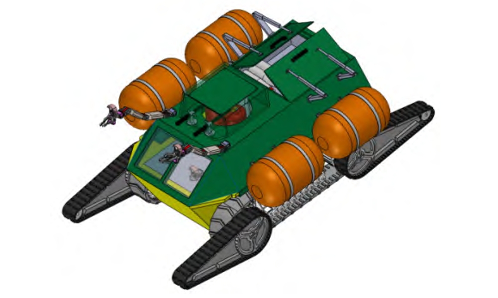
Our approach to robot technology emphasizes modularity and adaptability. The robot’s design targets five key scenarios: mountain forests, collapsed buildings, road obstacles, water accidents, and fire sites. To address these, we integrated three primary subsystems: a dual-swing-arm tracked walking mechanism, a buoyancy-propulsion water system, and a fire-extinguishing unit.
2.1 Technical Specifications
Table 1 summarizes the robot’s key technical parameters, highlighting its compact size, payload capacity, and mechanical specifications. These metrics were chosen to balance mobility with operational efficiency in diverse environments.
Table 1. Technical Parameters of the Amphibious Rescue Robot
| Project | Parameters |
|---|---|
| Overall Dimensions (unfolded) | 1300×950×800 mm (L×W×H) |
| Dual-Swing-Arm Extended Length | 1800 mm |
| Weight (满载 / Loaded) | 300 kg (350 kg) |
| Motor Model | NMRV40 gear motor |
| Motor Torque | 19 N·m |
| Gear Ratio | 30 |
The robot’s chassis employs a fully sealed welded structure with waterproof sealant, ensuring water resistance. The body is constructed from aluminum alloy, providing a balance of strength and buoyancy for aquatic operations.
3. Dual-Swing-Arm Tracked Walking Mechanism
The dual-swing-arm tracked system represents a pivotal innovation in robot technology for this project. This mechanism enhances terrain adaptability by distributing weight evenly and allowing independent adjustment of each swing arm, crucial for navigating uneven surfaces.
3.1 Mechanical Structure
As illustrated in Table 2, the walking mechanism comprises main tracks, front/rear swing arms, drive shafts, load wheels, and worm gear motors. Two NMRV high-torque gear motors provide forward propulsion through track engagement, while separate motors on each swing arm enable angular adjustment via drive shafts.
Table 2. Components of the Dual-Swing-Arm Tracked System
| Component | Function |
|---|---|
| Main Tracks | Provide traction and mobility on land |
| Front/Rear Swing Arms | Adjust to terrain contours for obstacle crossing |
| Drive Shafts | Transmit power from motors to swing arms |
| Load Wheels | Enhance stability and weight distribution |
| Worm Gear Motors | Deliver high torque for low-speed maneuvering |
3.2 Material and Traction Design
Rubber tracks were selected for their high friction coefficient and anti-slip properties, critical for maintaining grip on loose or wet surfaces. The dual-swing-arm design offers two key advantages:
- Weight Distribution: Evenly spreads the robot’s mass across uneven terrain.
- Independent Adjustment: Allows each arm to conform to obstacles, improving traversal efficiency.
Mathematically, the traction force T generated by the tracks is calculated using:\(T = \frac{M \times i}{R}\) where \(M = 19 \, \text{N·m}\) (motor torque), \(i = 30\) (gear ratio), and \(R = 0.25 \, \text{m}\) (drive wheel radius). Substituting these values yields \(T = 2280 \, \text{N}\), a critical parameter for obstacle negotiation analysis.
4. Water Travel System
For amphibious functionality, the robot incorporates a buoyancy-propulsion system, a key component of its robot technology integration. This system enables seamless transition from land to water, addressing rescue needs in flood zones or maritime incidents.
4.1 Buoyancy and Propulsion Components
Table 3 outlines the water travel system’s components, including high-strength inflatable airbags and aluminum propellers. The airbags, secured via quick-release aluminum clips, provide buoyancy when deployed and can be detached for land operations.
Table 3. Water Travel System Components
| Component | Material/Model | Function |
|---|---|---|
| Airbags | High-strength tear-resistant material | Provide buoyancy in water |
| Propellers | Yamaha marine outboard, aluminum | Generate thrust for water navigation |
| Brushless Motors | S1800 model | Drive propellers with high efficiency |
4.2 Technical Specifications
The propellers are driven by 900W brushless motors, capable of pushing a maximum load of 1100 kg and achieving a top speed of 12 km/h. These specifications ensure rapid response in water-based rescue scenarios, a testament to the robot technology’s adaptability.
5. Fire-Extinguishing Unit
Integrating firefighting capabilities into robot technology, the robot features a compact yet powerful fire-extinguishing system. This unit is designed to detect and suppress fires autonomously, reducing risk to human responders.
5.1 System Structure
The fire-extinguishing unit (Table 4) includes a dry powder extinguisher, electric push rod, and fire compartment. When a fire sensor detects heat, the STM32 controller activates the push rod to release the extinguisher’s trigger, initiating discharge.
Table 4. Fire-Extinguishing Unit Components
| Component | Function |
|---|---|
| Dry Powder Extinguisher | Stores fire-suppressing agent |
| Electric Push Rod | Mechanically activates the extinguisher |
| Fire Compartment | Houses the extinguisher and deployment mechanism |
| Sensor Interface | Connects to fire detection sensors |
5.2 Operational Simplicity
Refilling the extinguisher is straightforward: loosen the compartment lid, replace the extinguisher, and secure the nozzle with a clamp. This design prioritizes field usability, a key aspect of effective robot technology.
6. Performance Analysis
To validate the robot’s viability, we conducted two critical analyses: obstacle-crossing performance and component strength verification, both fundamental to robust robot technology.
6.1 Obstacle-Crossing Performance
When climbing slopes, the robot must overcome three primary forces: rolling resistance (\(F_f\)), internal friction (\(F_n\)), and gravitational force (\(G \sin \alpha\)). The total resistance \(\sum F\) is given by:\(\sum F = G \sin \alpha + F_f + F_n\) where:
- \(F_f = f G \cos \alpha\) (rolling resistance, \(f = 0.02\) for rough terrain),
- \(F_n = f_n G\) (internal friction, \(f_n = 0.06\)),
- \(G = 350 \, \text{kg} \times 9.81 \, \text{m/s}^2 = 3433.5 \, \text{N}\) (满载重量 /loaded weight).
For a 30° slope (\(\alpha = 30^\circ\)):\(\sum F = 3433.5 \sin 30^\circ + 0.02 \times 3433.5 \cos 30^\circ + 0.06 \times 3433.5\)\(= 1716.75 + 59.4 + 206.01 = 1982.16 \, \text{N}\)
Comparing this to the traction force \(T = 2280 \, \text{N}\), the robot can safely navigate slopes up to 30°, confirming its robust obstacle-crossing capability.
6.2 Structural Strength Verification
Using SolidWorks Simulation, we analyzed the front drive shaft, a critical component in the swing-arm mechanism. Made from carbon steel (yield strength = 220.594 MPa), the shaft was subjected to a 50 N·m torque. Simulation results showed a maximum stress of 88.4 MPa and deformation of \(2.708 \times 10^{-4} \, \text{mm}\), both well below allowable limits, validating the design’s structural integrity.
7. Conclusion
This dual-swing-arm tracked amphibious rescue robot exemplifies the potential of robot technology in enhancing emergency response capabilities. By integrating modular design, amphibious mobility, and autonomous firefighting, the system addresses critical gaps in traditional rescue operations. The mechanical analyses confirm its ability to navigate challenging terrains and withstand operational stresses, underscoring the effectiveness of our robot technology approach.
Looking ahead, future iterations may incorporate advanced sensor arrays and AI-driven path planning to further enhance autonomy, solidifying the role of robot technology in revolutionizing disaster response.