
In the design of modern HVAC control systems, damper actuators are critical components that convert electrical energy into mechanical torque to regulate air flow. This study presents a comprehensive design, analysis, and validation of a novel damper actuator transmission system employing a harmonic drive gear. The conventional multi-stage spur gear transmission is replaced with a compact, high-ratio harmonic drive, leading to a significant reduction in part count and assembly complexity. The design process encompasses scheme selection, parametric design, material selection, kinematic simulation, and static finite element analysis, culminating in a prototype that meets and exceeds the performance requirements of its predecessor.
1. Design Philosophy and Methodology
Our design approach follows a systematic, iterative process to ensure the final transmission structure is both reliable and optimal for the application. The methodology is outlined as follows:
- Requirements Definition: The design is initiated with a set of known parameters derived from a target commercial damper actuator. These parameters, including transmission ratio, maximum output torque, input speed, physical dimensions, stroke, cycle time, operational life, and environmental conditions, serve as the foundational constraints.
- Transmission Scheme Selection: Based on the requirement for a very high reduction ratio within a confined space, a harmonic drive gear is selected as the core transmission mechanism. Specific multi-stage harmonic drive configurations are evaluated.
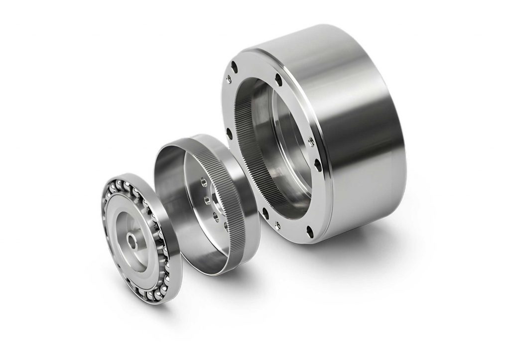
- Parametric Design: Key meshing parameters such as number of teeth and module are selected. The structural design of the three core components—the wave generator, the flexspline (FS), and the circular spline (CS)—is then completed.
- Theoretical Verification: Critical calculations are performed, including wear resistance analysis of the tooth surfaces and fatigue strength calculation of the flexspline. If these checks fail, the process returns to step (2) for parameter re-selection.
- 3D Modeling: A detailed three-dimensional model of all components is created and assembled in CAD software.
- Kinematic Simulation: A rigid-flexible coupled multibody dynamics model is constructed for kinematic simulation to verify motion correctness and ratio. Failure here necessitates a review of the model and assembly.
- Finite Element Analysis (FEA): A static structural analysis of the transmission assembly is conducted under maximum load. Success here validates the design for prototyping and manufacturing.
2. Transmission Scheme Analysis and Selection
2.1. Analysis of Conventional Design
The baseline damper actuator utilizes a multi-stage plastic spur gear train to achieve its high reduction ratio. This design, while functional, requires a large number of small, high-precision gears. The cumulative effect of tolerances and the need for numerous injection molds results in higher manufacturing costs and potential reliability concerns due to the complexity of the assembly.
2.2. Harmonic Drive Gear Configuration
To overcome these limitations, we focus on the harmonic drive gear, renowned for its high single-stage reduction ratio, compactness, high precision, and low backlash. For applications requiring an exceptionally high total ratio (i > 7,000), a dual-stage harmonic drive is necessary. We evaluated three primary configurations for compound harmonic drives:
- Scheme A: The flexspline of the first stage is connected to the wave generator of the second stage; the second-stage flexspline is fixed; the two circular splines are connected for output. This scheme results in a larger radial dimension.
- Scheme B: The circular spline of the first stage is connected to the wave generator of the second stage; the second-stage circular spline is fixed; the two flexsplines are connected for output. This scheme leads to a larger axial dimension.
- Scheme C: A dual-flexspline, single-wave-generator configuration where the first-stage circular spline is fixed and the second-stage circular spline provides the output.
Considering the specific dimensional constraints of a damper actuator housing, Scheme C offers the most balanced volumetric efficiency. Although its theoretical mechanical efficiency is slightly lower than the others, the damper actuator’s intermittent duty cycle and relatively low output power make this trade-off acceptable. The final transmission schematic is shown in the conceptual diagram below. To achieve the correct final output direction, a final bevel gear stage is added after the harmonic drive output.
3. Parametric Design and Calculation
3.1. System Requirements and Target Parameters
The design targets are based on an existing commercial unit. The key performance and dimensional requirements are summarized in Table 1.
| Parameter | Value |
|---|---|
| Input Speed, \( n_1 \) (rpm) | 1,191 |
| Total Transmission Ratio, \( i_{total} \) | 7,143 |
| Output Torque, \( T_{out} \) (N·m) | 15 |
| Overall Dimensions (mm) | 134 × 66 × 62 |
| Stroke (°) | 95 |
| Operational Life (cycles) | 60,000 |
3.2. Harmonic Drive Gear Parameters
Following standard harmonic drive design procedures, the primary geometric parameters for the dual-flexspline design are determined. The wave generator employs a standard elliptical cam. The contour of this cam in polar coordinates is defined by:
$$ \rho_H(\phi_H) = \frac{a_H b_H}{\sqrt{{a_H}^2 \sin^2 \phi_H + {b_H}^2 \cos^2 \phi_H}} $$
where \( \rho_H \) is the radial distance, \( \phi_H \) is the angle, \( a_H = 15.44 \text{ mm} \) is the semi-major axis, and \( b_H = 14.84 \text{ mm} \) is the semi-minor axis. The key design parameters for the prototype are listed in Table 2.
| Parameter | Value |
|---|---|
| Reference Pressure Angle, \( \alpha_0 \) (°) | 20 |
| Harmonic Gear Module, \( m_1 \) (mm) | 0.3 |
| 1st Stage Flexspline Teeth, \( Z_{R1} \) | 168 |
| 2nd Stage Flexspline Teeth, \( Z_{R2} \) | 170 |
| Fixed Circular Spline Teeth, \( Z_{G1} \) | 170 |
| Output Circular Spline Teeth, \( Z_{G2} \) | 172 |
| Bevel Gear Module, \( m_2 \) (mm) | 1 |
| Bevel Gear Teeth (Pinion/Wheel), \( Z_5 / Z_6 \) | 16 / 32 |
The theoretical reduction ratio of the harmonic drive section (Scheme C) is given by:
$$ i_{harmonic} = \frac{Z_{R1} \cdot Z_{G2}}{(Z_{G1} – Z_{R1}) \cdot (Z_{G2} – Z_{R2})} = \frac{168 \times 172}{(170-168) \times (172-170)} = \frac{168 \times 172}{2 \times 2} = 7,224 $$
The bevel gear stage provides a ratio of \( i_{bevel} = Z_6 / Z_5 = 2 \). The total theoretical ratio is:
$$ i_{total\_theory} = i_{harmonic} \times i_{bevel} = 7,224 \times 2 = 14,448 $$
This exceeds the required 7,143, providing a design margin and allowing for speed adjustment via motor control to meet the specified actuator closing time.
4. Material Selection and Component Strength Analysis
4.1. Rationale for Engineering Plastics
To drastically reduce cost and improve manufacturability, we propose using engineering plastics instead of alloy steel for all gear components. The flexspline, a critically stressed component undergoing cyclic elastic deformation, requires good strength, elasticity, and fatigue resistance. Nylon 1010 is selected for the flexspline and the flexible bearing elements due to its excellent comprehensive properties. The more rigid components (circular splines, bevel gears, housing) are made from Polyoxymethylene (POM), known for its high stiffness, low friction, and good dimensional stability. Their key properties are compared in Table 3.
| Property | Nylon 1010 | POM (Homopolymer) |
|---|---|---|
| Tensile Strength, \( \sigma_b \) (MPa) | 55 | 70 |
| Flexural Strength, \( \sigma_s \) (MPa) | 85 | 98 |
| Fatigue Strength (Reverse Bending), \( \sigma_{-1} \) (MPa) | 24 | 35 |
4.2. Flexspline Strength Verification
The primary failure modes for a plastic harmonic drive gear are tooth surface wear and flexspline fatigue fracture. We conduct the necessary verification calculations.
1. Tooth Surface Pressure (Wear) Check: The maximum contact pressure \( p \) on the tooth flank is estimated using the formula:
$$ p = \frac{K \cdot T_1}{\phi_d \cdot d_1 \cdot h_n \cdot Z_v} $$
where \( K=1 \) is the load factor, \( T_1=20 \text{ N·m} \) is the torque on the flexspline, \( \phi_d=0.21 \) is the face width coefficient, \( d_1=50.4 \text{ mm} \) is the pitch diameter, \( h_n=0.45 \text{ mm} \) is the working tooth height, and \( Z_v=21 \) is the number of simultaneously engaged teeth. Calculation yields \( p \approx 8.12 \text{ MPa} \). The allowable pressure for Nylon 1010 is \( [p] = 8 \text{ MPa} \). Since \( p \approx [p] \), the wear resistance is considered acceptable for the intended service life.
2. Fatigue Strength Check: The safety factor \( S \) for combined alternating stress in the flexspline cup is calculated based on the Goodman criterion. The calculated stress amplitudes \( \sigma_a \) and \( \tau_a \), mean stresses \( \sigma_m \) and \( \tau_m \), and the effective stress concentration factors \( K_\sigma \) and \( K_\tau \) are used.
$$ S_\sigma = \frac{\sigma_{-1}}{K_\sigma \sigma_a + \psi_\sigma \sigma_m}, \quad S_\tau = \frac{\tau_{-1}}{K_\tau \tau_a + \psi_\tau \tau_m} $$
$$ S = \frac{S_\sigma S_\tau}{\sqrt{S_\sigma^2 + S_\tau^2}} $$
The resulting safety factor is \( S = 3 \), which is greater than the minimum allowable value of \( [S] = 1.5 \). Therefore, the flexspline’s fatigue strength is sufficient.
3. Buckling Stability Check: To prevent elastic instability of the thin-walled cup under torsion, the critical shear stress \( \tau_{cr} \) is calculated and must satisfy:
$$ \tau_{cr} > \tau_{TC} \quad \text{and} \quad \frac{\tau_{cr}}{\tau_T} \ge 2 $$
where \( \tau_{TC} \) and \( \tau_T \) are the shear stresses from torque and tangential forces, respectively. The analysis confirms \( \tau_{cr} = 168.23 \text{ MPa} > \tau_{TC} = 3.31 \text{ MPa} \) and \( \tau_{cr} / \tau_T = 114 \gg 2 \), ensuring no risk of buckling.
5. Kinematic Simulation and Model Validation
A virtual prototype was assembled in SolidWorks and imported into ADAMS/View for multi-body dynamics simulation. Materials were assigned, and appropriate joints (fixed, revolute) and constraints (couplers) were applied to model the interactions: the wave generator driving the flexspline, the meshing between flexspline teeth and circular spline teeth, and the final bevel gear stage. A rotational velocity drive of 7,146 °/s (1,191 rpm) was applied to the input shaft using a STEP function for smooth start-up, and a 15 N·m load torque was applied to the output bevel gear.
The simulation results provided clear velocity profiles for all rotating components. The key findings were:
- The direction of rotation for each stage conformed perfectly to the kinematic principles of the compound harmonic drive gear and the subsequent bevel gear stage.
- The steady-state velocity ratio between the input wave generator and the final output was confirmed to be 14,448:1, matching the theoretical calculation and validating the geometric accuracy of the 3D model and the constraint definitions.
This successful kinematic simulation confirms the fundamental correctness of the transmission design and provides a reliable digital model for subsequent dynamic and structural analyses.
6. Finite Element Static Structural Analysis
To evaluate the structural integrity under maximum load, a static Finite Element Analysis (FEA) was performed on the complete transmission assembly using ANSYS. The model was simplified by treating the wave generator as a single part. Contacts were defined between all mating gear teeth (flexspline/circular spline, bevel gears) and between the flexspline cup and the wave generator. A friction coefficient of 0.1 was used for all contacts. The fixed circular spline was constrained in all degrees of freedom. A cylindrical support was applied to the output components, allowing only rotation. A demanding load torque of 45 N·m (three times the rated torque) was applied to the output bevel gear to test the design’s safety margin.
The results of the FEA are summarized below. The maximum values for key metrics are listed in Table 4, and the stress distribution is visualized in the accompanying figures (conceptually represented by the analysis contours).
| Result Parameter | Maximum Value |
|---|---|
| Total Deformation | 0.0235 mm |
| Equivalent (von-Mises) Stress | 11.521 MPa |
| Maximum Principal Stress | 14.682 MPa |
| Minimum Principal Stress | -12.159 MPa |
The analysis reveals that the maximum deformation is negligible (0.0235 mm). The maximum equivalent stress of 11.521 MPa occurs on the teeth of the output bevel gear. This value is slightly below the allowable stress for POM (Yield Strength / Safety Factor ≈ 70 MPa / 6 ≈ 11.67 MPa, assuming a conservative safety factor of 6 for plastic gears under dynamic loads). The high stress concentration is expected due to the geometry of the gear teeth. Crucially, the flexspline, the most critical component, shows stress levels well within the fatigue limit of Nylon 1010. This analysis demonstrates that the transmission structure, largely built with engineering plastics, can safely withstand a load of 45 N·m, providing a significant safety factor relative to the required 15 N·m operational torque.
7. Conclusion
This study successfully details the complete design process for a damper actuator transmission based on a compound harmonic drive gear. By replacing a conventional multi-stage spur gear train with an optimized dual-flexspline harmonic drive, we achieve a more compact, simpler, and potentially more cost-effective solution. The parametric design was rigorously verified through theoretical strength calculations for wear and fatigue. The kinematic simulation in ADAMS validated the correct motion and achievement of the targeted ultra-high reduction ratio. Finally, a static finite element analysis under an overload condition confirmed the structural integrity of the plastic components, showing that the design possesses a robust safety margin. The results conclusively demonstrate that the proposed harmonic drive gear-based transmission is not only feasible but also offers performance advantages, meeting and exceeding the specifications of the original damper actuator design. This work provides a solid theoretical and simulation-based foundation for the prototyping and eventual productization of this innovative actuator.