
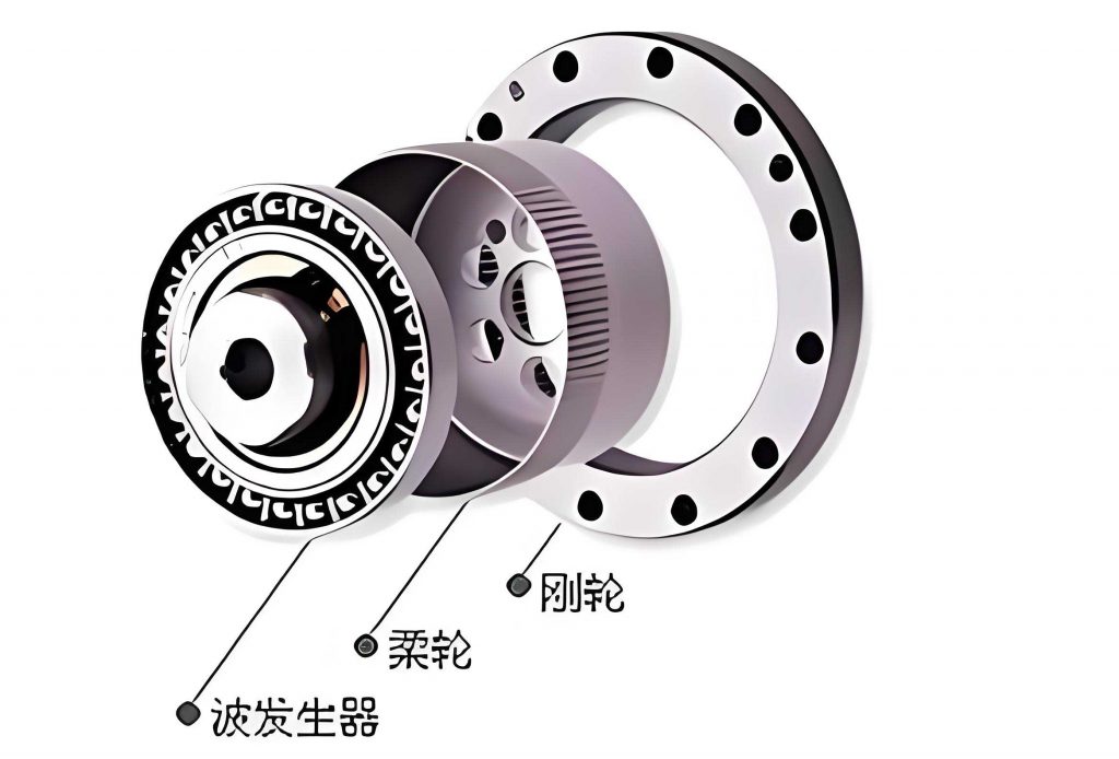
In modern industrial applications, strain wave gears have become indispensable due to their unique characteristics, such as high precision, compact design, and excellent torque transmission capabilities. These gears are widely used in robotics, aerospace, medical devices, and automation systems. Traditionally, the manufacturing of strain wave gears involves processes like forging, turning, and gear cutting (e.g., hobbing or shaping), which are time-consuming, costly, and inefficient for mass production. Moreover, the small module (typically less than 1) of strain wave gears makes it difficult to apply finishing methods like grinding or honing, limiting further improvements in accuracy. To address these challenges, cold rolling has emerged as a promising alternative, offering higher efficiency, better material utilization, and enhanced mechanical properties through work hardening. However, achieving precise tooth formation, especially in terms of pitch accuracy, remains a critical issue in cold rolling of strain wave gears. This article explores the factors influencing tooth accuracy from a first-person perspective, focusing on the cold rolling process, variable pitch phenomena, and system-level considerations.
The cold rolling process for strain wave gears involves plastic deformation of a gear blank under pressure, where rolling tools (rolls) and the blank perform generating motions while feeding radially. Essentially, the roll teeth gradually penetrate the blank, causing metal to flow and form the desired tooth profile through successive rolling passes. This method preserves the continuity of metal fiber lines, improves surface integrity, and increases fatigue strength. A typical setup uses two synchronized rolls that rotate in the same direction, with the blank mounted on a mandrel and allowed to rotate freely or be driven. The rolls apply radial force to deform the blank, and the generating motion ensures the correct tooth geometry. The process can be divided into distinct stages, each affecting the final gear accuracy. Understanding these stages is crucial for optimizing the manufacturing of strain wave gears.
One of the core aspects of cold rolling strain wave gears is the variable pitch phenomenon. During rolling, the pitch of the gear teeth changes dynamically as the pitch circle diameter varies across different stages. This occurs because the rolling process is not a constant-diameter operation; instead, the engagement between the roll and blank shifts from the blank’s outer diameter to its final pitch diameter. The process can be segmented into three phases: the initial engagement phase, the forming phase, and the finishing phase. In the initial phase, the roll’s tip circle contacts the blank’s outer diameter, and the pitch is determined by the blank’s outer circumference. As rolling progresses in the forming phase, the pitch circle diameter continuously changes due to radial feed, leading to a variable pitch. Finally, in the finishing phase, the roll and blank achieve pure rolling at the pitch circle, stabilizing the pitch. This variable pitch nature necessitates precise control over the entire system to ensure accurate tooth division in strain wave gears.
To quantify the variable pitch, consider the pitch formula derived from gear geometry. For a gear with pitch diameter \(d\) and number of teeth \(z\), the circular pitch \(p\) is given by:
$$ p = \frac{\pi d}{z} $$
During cold rolling, the pitch diameter \(d\) changes from the blank’s outer diameter \(d_k\) in the initial phase to the final pitch diameter \(d_{20}\) in the finishing phase. Thus, the pitch varies as:
$$ p_i = \frac{\pi d_i}{z} $$
where \(d_i\) represents the instantaneous pitch diameter at any stage \(i\). This variation directly impacts tooth accuracy, as incorrect pitch can lead to defects like multi-toothing, missing teeth, or uneven distribution. For strain wave gears, which require high precision for smooth transmission, managing this variation is essential. The table below summarizes the pitch changes across the three phases:
| Phase | Pitch Diameter | Circular Pitch | Description |
|---|---|---|---|
| Initial Engagement | \(d_k\) (blank outer diameter) | \(p_a = \frac{\pi d_k}{z_2}\) | Roll tip engages blank outer surface; initial tooth division occurs. |
| Forming | \(d_i\) (variable diameter) | \(p_i = \frac{\pi d_i}{z_2}\) | Radial feed changes diameter; pitch varies dynamically. |
| Finishing | \(d_{20}\) (final pitch diameter) | \(p_e = \frac{\pi d_{20}}{z_2}\) | Pure rolling at pitch circle; pitch stabilizes to design value. |
The accuracy of strain wave gears in cold rolling is influenced by multiple factors within the process system, including the gear blank diameter, roll geometry, and motion control of the rolling apparatus. Each factor interacts with the variable pitch phenomenon, and a systematic analysis is necessary to optimize precision.
First, the diameter of the gear blank \(d_k\) is a critical parameter. It must be calculated based on the volume constancy principle to ensure proper tooth formation without defects. If the blank diameter is too small, the teeth may be incomplete or undersized; if too large, excess material can cause burrs or irregular shapes. For strain wave gears, the blank diameter directly affects the initial pitch in the engagement phase. According to volume constancy, the volume of the blank should equal the volume of the finished gear, accounting for metal flow during rolling. The formula for blank diameter can be derived from gear geometry and material properties. For instance, considering a strain wave gear with module \(m\), number of teeth \(z_2\), and face width \(b\), the approximate blank diameter \(d_k\) can be expressed as:
$$ d_k \approx \sqrt{d_{20}^2 + \frac{4V}{\pi b}} $$
where \(V\) is the volume of tooth material, and \(d_{20}\) is the final pitch diameter. However, precise calculation requires iterative methods or finite element analysis due to complex metal flow. In practice, an incorrect blank diameter can lead to pitch errors, as the initial division relies on the roll’s tip circle rolling on the blank’s outer surface. This highlights the importance of accurate blank sizing for strain wave gear quality.
Second, the geometric parameters of the rolls play a vital role. The rolls must have the same module and pressure angle as the strain wave gear being produced. To ensure longevity, the roll diameter should be as large as possible within machine constraints, often achieved by maximizing the number of roll teeth \(z_1\). Additionally, for free indexing processes (where no separate indexing device is used), the roll’s tip circle diameter \(d_{a1}\) must satisfy a specific relationship with the blank diameter \(d_k\) to achieve correct tooth division. From gear meshing principles, the circular pitches of the roll and blank must match during initial engagement. Thus:
$$ \frac{\pi d_{a1}}{z_1} = \frac{\pi d_k}{z_2} $$
Simplifying, we get:
$$ d_{a1} = d_k \cdot \frac{z_1}{z_2} $$
This equation ensures that the roll properly divides the blank into the required number of teeth for strain wave gears. However, due to the variable pitch nature, rolls with constant pitch may not suffice for dynamic accuracy. Ideally, the roll should have a variable pitch along its circumference to match the changing pitch during rolling, but this is technically challenging for gear-shaped tools. As an alternative, motion compensation through servo control can be employed, adjusting the blank’s rotation speed in real-time. The table below outlines key roll parameters and their effects on strain wave gear accuracy:
| Roll Parameter | Effect on Accuracy | Optimization Strategy |
|---|---|---|
| Tip Circle Diameter \(d_{a1}\) | Determines initial pitch division; deviations cause tooth count errors. | Calculate using \(d_{a1} = d_k \cdot (z_1/z_2)\); ensure precise manufacturing. |
| Module and Pressure Angle | Must match gear design; mismatches lead to profile inaccuracies. | Use standard tooling; verify tolerances through inspection. |
| Number of Teeth \(z_1\) | Affects roll durability and smoothness of rolling; more teeth reduce load per tooth. | Maximize \(z_1\) within machine limits; consider negative profile shift if needed. |
| Pitch Variation Capability | Constant pitch rolls may not adapt to variable pitch process, causing dynamic errors. | Implement motion compensation or use tailored roll designs for strain wave gears. |
Third, the motion control of the rolling apparatus is crucial for managing variable pitch in strain wave gears. Modern cold rolling machines often employ digital servo systems to synchronize the roll and blank rotations while controlling radial feed. This allows for forced rolling, where the blank’s speed is adjusted dynamically to maintain correct pitch as the diameter changes. The machine typically has three axes: two rotational axes for the rolls (C2) and blank (C1), and one linear axis for radial feed (X). The motion relationship ensures generating motion and feed simultaneously. During rolling, the roll speed \(n_1\) is kept constant, while the blank speed \(n_2\) is varied based on the instantaneous pitch diameter \(d_i\). From kinematics, the rolling condition requires:
$$ n_1 d_1 = n_2 d_i $$
where \(d_1\) is the roll’s pitch diameter, and \(d_i\) is the blank’s instantaneous pitch diameter. In the initial phase, \(d_i = d_k\), so the blank speed \(n_{2a}\) is:
$$ n_{2a} = n_1 \cdot \frac{d_{a1}}{d_k} $$
In the finishing phase, \(d_i = d_{20}\), and the speed ratio is:
$$ n_{2e} = n_1 \cdot \frac{d_1}{d_{20}} $$
During the forming phase, \(d_i\) changes continuously, and the blank speed \(n_{2i}\) must be adjusted as:
$$ n_{2i} = n_1 \cdot \frac{d_1}{d_i} $$
This dynamic compensation ensures that the circular pitch remains consistent with the design, even as the diameter varies. Without such control, pitch errors accumulate, degrading the accuracy of strain wave gears. The integration of CNC systems enables precise coordination, but it requires accurate modeling of the rolling process. The following formula summarizes the speed compensation for variable pitch in strain wave gear rolling:
$$ n_2 = \begin{cases}
n_1 \cdot \frac{d_{a1}}{d_k} & \text{for initial engagement} \\
n_1 \cdot \frac{d_1}{d_i} & \text{for forming phase} \\
n_1 \cdot \frac{d_1}{d_{20}} & \text{for finishing phase}
\end{cases} $$
To further illustrate the factors affecting strain wave gear accuracy, a comprehensive table is provided below, combining all elements discussed:
| Factor | Impact on Tooth Accuracy | Mathematical Relation | Practical Consideration |
|---|---|---|---|
| Blank Diameter \(d_k\) | Determines initial pitch; errors cause multi-toothing or missing teeth. | \(p_a = \pi d_k / z_2\); volume constancy for sizing. | Calculate using CAD/FEA; adjust for material flow in strain wave gears. |
| Roll Tip Diameter \(d_{a1}\) | Ensures correct tooth division in free indexing; deviations lead to pitch inaccuracies. | \(d_{a1} = d_k \cdot (z_1/z_2)\) from meshing condition. | Manufacture rolls with high precision; consider wear effects over time. |
| Variable Pitch Phenomenon | Causes dynamic pitch changes; if unmanaged, results in uneven tooth spacing. | \(p_i = \pi d_i / z_2\); \(d_i\) varies with radial feed. | Implement real-time speed compensation; design rolls for adaptive pitching. |
| Motion Control (Servo System) | Enforces correct speed ratios for dynamic pitch; inaccuracies cause cumulative errors. | \(n_1 d_1 = n_2 d_i\); adjust \(n_2\) based on \(d_i\). | Use CNC with high-resolution encoders; calibrate for strain wave gear specifics. |
| Material Properties | Affects plastic deformation and springback; influences final tooth profile. | Stress-strain relations: \(\sigma = K \epsilon^n\) for work hardening. | Select ductile materials; pre-treat blanks to reduce variability in strain wave gears. |
| Radial Feed Rate | Controls metal flow and tooth height; excessive feed can cause defects. | Feed \(\Delta r\) per revolution; related to reduction ratio. | Optimize via trial runs; monitor for consistent forming in strain wave gears. |
In conclusion, the cold rolling of strain wave gears is a complex process where tooth accuracy is heavily influenced by the interplay of blank diameter, roll geometry, and motion control. The variable pitch nature of rolling necessitates dynamic adjustments to maintain precise tooth division. From my analysis, key takeaways include: the blank diameter must be optimized using volume constancy principles to avoid initial pitch errors; roll design should account for meshing conditions and ideally incorporate variable pitch capabilities, though motion compensation can suffice; and servo-controlled systems must dynamically adjust blank speed to match changing pitch diameters. These factors collectively determine the success of manufacturing high-precision strain wave gears via cold rolling. Future work could focus on advanced modeling techniques, such as finite element analysis, to predict metal flow and optimize parameters for specific strain wave gear applications. By addressing these elements, manufacturers can improve efficiency and accuracy, enabling broader adoption of cold rolling for strain wave gears in industries requiring high-performance gear systems.
Additionally, the integration of smart manufacturing technologies, like IoT sensors and AI-based monitoring, could further enhance quality control by detecting real-time deviations in pitch or profile during rolling. For strain wave gears, which often operate in critical applications, such improvements are invaluable. Ultimately, a holistic approach that considers the entire process system—from blank preparation to final finishing—will yield the best results for cold rolling strain wave gears, ensuring they meet the stringent demands of modern engineering.