
In the realm of mechanical transmission systems, the spherical gear represents a groundbreaking innovation that transcends the limitations of conventional gear types such as cylindrical, conical, and non-cylindrical gears. While traditional gears operate with a single degree of freedom, facilitating one-dimensional rotational motion between fixed axes, the spherical gear introduces a paradigm shift by offering two degrees of freedom. This enables the transmission of two-dimensional rotational motion, mirroring the natural articulation found in biological joints. This unique capability has spurred interest in applications like biomimetic robotics, particularly in flexible wrist mechanisms for painting robots. However, despite its potential, the widespread adoption of spherical gears has been hindered by challenges related to transmission accuracy and manufacturing complexity. In this paper, I delve into the theoretical foundations and kinematic behavior of spherical gear transmissions, proposing a novel design based on annular involute surfaces to overcome existing limitations. Through detailed analysis, I aim to establish a comprehensive framework for understanding and implementing spherical gear systems.
The concept of spherical gear transmission originated over a decade ago with innovations by engineers in Norway, capturing the attention of researchers worldwide. Unlike discrete-tooth spherical gears that suffer from imprecise motion due to irregular tooth distribution and contact points outside the motion plane, my approach focuses on continuous tooth distribution and adherence to gear meshing fundamentals. This ensures exact transmission ratios and enhances practicality. The core idea revolves around transforming a planar gear pair into a spherical configuration by rotating it around a polar axis, leading to the formation of annular tooth rings on a spherical surface. This geometric transformation preserves the kinematic properties of involute profiles while enabling multi-directional motion. As I explore this topic, I will repeatedly emphasize the term “spherical gear” to underscore its centrality in this discussion, highlighting its unique attributes and potential applications in advanced machinery.
To lay the groundwork, let me define key concepts associated with spherical gear systems. These definitions are crucial for understanding the subsequent analysis and design principles. The table below summarizes the fundamental terminology:
| Term | Definition |
|---|---|
| Polar Axis | A line passing through the sphere center and perpendicular to the tooth ring plane, serving as the rotation axis during manufacturing. |
| Tooth Ring | A ring-shaped body formed by revolving a planar tooth profile around the polar axis. |
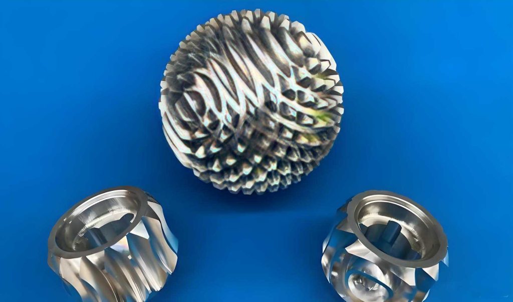
| Convex Spherical Gear | A spherical gear where the polar axis end features a cylindrical rotary body as teeth. |
| Concave Spherical Gear | A spherical gear where the polar axis end has a rotary recess, creating a concave structure. |
| Tip Sphere | The sphere generated by revolving the addendum circle of the planar gear around the polar axis. |
| Root Sphere | The sphere generated by revolving the dedendum circle of the planar gear around the polar axis. |
| Pitch Sphere | The sphere generated by revolving the pitch circle of the planar gear around the polar axis, analogous to the pitch circle in cylindrical gears. |
| Base Sphere | The sphere generated by revolving the base circle of the planar gear around the polar axis, fundamental for involute generation. |
| Mesh Cone | The conical surface formed by the collection of contact points during meshing of two spherical gears. |
The generation of tooth profiles in a spherical gear is rooted in the involute curve, which ensures smooth and precise motion transmission. Consider a generating line in contact with a base circle within a plane containing the polar axis. As this line rolls without slipping on the base circle while the plane rotates around the polar axis, any point on the generating line traces an annular involute surface. Mathematically, this can be expressed using parametric equations. Let the base circle lie in a plane with the polar axis as the z-axis. The coordinates of a point on the involute surface are derived from the rolling motion and rotation. For a generating line parameterized by an angle $\theta$ from the base circle, the position vector $\vec{r}$ in spherical coordinates $(R, \phi, \psi)$ is given by:
$$ \vec{r}(\theta, \psi) = R_b \left( \cos(\theta + \psi) \hat{i} + \sin(\theta + \psi) \hat{j} \right) + R_b \theta \sin\alpha \hat{k} $$
Here, $R_b$ is the base sphere radius, $\theta$ is the rolling angle, $\psi$ is the rotation angle around the polar axis, and $\alpha$ is the pressure angle. This formulation yields a continuous surface where every cross-section through the polar axis exhibits a standard involute curve. The integrity of this profile is vital for the spherical gear’s ability to maintain constant angular velocity ratios across various orientations. The following table outlines the geometric parameters involved in spherical gear design, emphasizing the parallels with cylindrical gears but adapted for spherical geometry:
| Parameter | Symbol | Description | Relation to Cylindrical Gear |
|---|---|---|---|
| Base Sphere Radius | $R_b$ | Radius of the sphere from which involutes are generated. | Analogous to base circle radius $r_b$. |
| Pitch Sphere Radius | $R_p$ | Radius of the sphere where meshing occurs without sliding. | Analogous to pitch circle radius $r_p$. |
| Pressure Angle | $\alpha$ | Angle between the tooth profile normal and the radial direction at the pitch point. | Same as in standard gears, typically 20° or 25°. |
| Module | $m$ | Ratio of pitch sphere diameter to number of teeth, defining tooth size. | Identical to module in cylindrical gears. |
| Number of Teeth | $z$ | Total teeth on the spherical gear, distributed across rings. | Directly comparable, but influenced by spherical curvature. |
Meshing characteristics of spherical gears are distinct due to their spherical nature. When two spherical gears engage, their pitch spheres roll purely against each other, resulting in point contact along a dynamically changing path. This contrasts with line contact in cylindrical gears but is sufficient for motion transmission. The contact point always lies in a plane that contains the polar axes and the sphere centers, ensuring the meshing follows the fundamental law of gearing. Specifically, the common normal at the contact point must pass through a fixed point on the line of centers, which for spherical gears translates to the sphere centers. The condition for correct meshing is derived from the equivalence to a planar gear pair, known as the equivalent spur gear. Thus, the correct meshing conditions for a pair of spherical gears are:
- The normal modules must be equal: $m_{n1} = m_{n2}$.
- The normal pressure angles must be equal: $\alpha_{n1} = \alpha_{n2}$.
- One spherical gear must be convex, and the other concave to allow pairing, meaning their polar axes align with tooth centers differently.
These conditions ensure that the spherical gears can engage smoothly across various orientations. Additionally, the contact ratio, which indicates the average number of tooth pairs in contact, is critical for continuous motion. For spherical gears, the contact ratio $\epsilon$ is calculated similarly to spur gears, using the equivalent tooth numbers $z_v1$ and $z_v2$:
$$ \epsilon = \frac{1}{2\pi} \left[ z_{v1} (\tan\alpha_{a1} – \tan\alpha’) + z_{v2} (\tan\alpha_{a2} – \tan\alpha’) \right] $$
Here, $\alpha_{a1}$ and $\alpha_{a2}$ are the tip pressure angles of the two spherical gears, and $\alpha’$ is the operating pressure angle. This formula underscores the importance of tooth geometry in maintaining uninterrupted power flow. To prevent undercutting during manufacturing, which is common when tooth numbers are low, modification via profile shifting is applicable. The minimum number of teeth to avoid undercutting for a spherical gear is given by $z_{min} = \frac{2}{\sin^2\alpha}$, akin to spur gears. Profile shift coefficients $x_1$ and $x_2$ can be introduced, altering the tooth thickness and center distance while preserving meshing integrity. The modified geometry ensures robust performance, especially in compact spherical gear designs where space constraints limit tooth size.
Structurally, spherical gears exhibit unique installation requirements due to their two-degree-of-freedom motion. They are typically mounted on a cross-shaped framework that allows rotation about two perpendicular axes, enabling the spherical gear to pivot within a limited angular range, often up to ±90°. This framework restricts the tooth distribution to a spherical cap rather than the entire sphere, optimizing weight and complexity. The initial assembly of a spherical gear pair requires the polar axes to be collinear, after which they can be adjusted to various relative orientations. The table below summarizes key structural and installation aspects:
| Aspect | Description | Implication for Design |
|---|---|---|
| Mounting Framework | A two-degree-of-freedom gimbal mechanism that supports the spherical gear. | Enables multi-directional motion but limits swing angle; input/output shafts are external. |
| Tooth Distribution | Teeth are arranged in concentric rings on a spherical cap, not the full sphere. | Reduces material usage and manufacturing cost while maintaining functionality. |
| Assembly Condition | Initial polar axis alignment is necessary for proper meshing. | Requires precise setup but allows subsequent misalignment compensation due to the separability property. |
| Separability | Similar to involute gears, spherical gears tolerate minor center distance variations without losing correct meshing. | Enhances robustness in real-world applications where alignment may drift. |
The kinematic analysis of spherical gears involves describing their motion as a composition of rotations about arbitrary axes through the sphere centers. Consider two spherical gears with sphere centers $O_1$ and $O_2$, each capable of rotating about their polar axes and secondary axes. Let $\beta_1$ and $\beta_2$ denote the rotation angles of the driving and driven spherical gears, respectively, about an instantaneous axis of rotation. For pure rolling between the pitch spheres, the angular velocities maintain a constant ratio inversely proportional to the pitch sphere radii $R_{p1}$ and $R_{p2}$:
$$ \frac{\omega_1}{\omega_2} = \frac{R_{p2}}{R_{p1}} = \frac{z_2}{z_1} $$
This relation holds when motion occurs in a plane containing the polar axes, i.e., the normal plane of the tooth profiles. However, for general spatial motion, the analysis becomes more complex. The overall motion can be decomposed into two sequential rotations: first about the x-axis by an angle $\Delta \gamma$, then about the y-axis by an angle $\Delta \eta$, or vice versa. Using rotation matrices, the transformation of a point on the output shaft from an initial position $\vec{p_0} = (x_0, y_0, z_0)$ to a new position $\vec{p}$ is given by:
$$ \vec{p} = R_y(\Delta \eta) R_x(\Delta \gamma) \vec{p_0} $$
where $R_x$ and $R_y$ are rotation matrices about the x and y axes, respectively. Expanding this, the coordinates become:
$$ x = x_0 \cos\Delta \eta + y_0 \sin\Delta \gamma \sin\Delta \eta + z_0 \cos\Delta \gamma \sin\Delta \eta $$
$$ y = y_0 \cos\Delta \gamma – z_0 \sin\Delta \gamma $$
$$ z = -x_0 \sin\Delta \eta + y_0 \sin\Delta \gamma \cos\Delta \eta + z_0 \cos\Delta \gamma \cos\Delta \eta $$
The direction cosines of the output shaft relative to the coordinate axes can be derived from these expressions. For instance, the angle $\Delta \zeta$ of the output shaft relative to the z-axis after the rotations is related to $\Delta \gamma$ and $\Delta \eta$ by:
$$ \cos\Delta \zeta = \cos\Delta \gamma \cos\Delta \eta $$
This illustrates that when the spherical gear moves in a direction not aligned with the tooth normal plane, the instantaneous transmission ratio may deviate from a constant value, as the tooth profile in that oblique section is not a perfect involute. Therefore, precise motion control requires accounting for these geometric nonlinearities. To facilitate understanding, I present a table of kinematic variables and their interrelationships:
| Variable | Symbol | Definition | Kinematic Relation |
|---|---|---|---|
| Rotation about x-axis | $\Delta \gamma$ | Angular displacement of the spherical gear around the x-axis of the frame. | Part of composite motion; influences output orientation. |
| Rotation about y-axis | $\Delta \eta$ | Angular displacement of the spherical gear around the y-axis of the frame. | Combined with $\Delta \gamma$ to determine net rotation. |
| Net rotation angle | $\Delta \zeta$ | Total angular displacement of the output shaft from initial position. | $\cos\Delta \zeta = \cos\Delta \gamma \cos\Delta \eta$. |
| Angular velocity ratio | $i$ | Ratio of input to output angular velocities in normal plane. | $i = \frac{\omega_1}{\omega_2} = \frac{z_2}{z_1}$ for standard spherical gears. |
| Instantaneous axis | $\hat{u}$ | Unit vector along the instantaneous axis of rotation. | Derived from Euler’s rotation theorem; varies with orientation. |
Expanding on the motion analysis, consider the case where the driving spherical gear undergoes two independent rotations $\Delta \gamma_1$ and $\Delta \eta_1$, and the driven spherical gear undergoes $\Delta \gamma_2$ and $\Delta \eta_2$. The relationship between these angles is governed by the gear ratio and the geometry of the pitch spheres. For small displacements, linear approximations can be used, but for large angles, nonlinear trigonometric equations apply. The condition for pure rolling without sliding at the contact point leads to a set of differential equations relating the angular velocities. In terms of time derivatives, we have:
$$ \frac{d\beta_1}{dt} = \frac{R_{p2}}{R_{p1}} \frac{d\beta_2}{dt} $$
when the motion is confined to the normal plane. In general spatial motion, the velocity of the contact point on both spherical gears must be equal, leading to vector equations that incorporate the cross products of angular velocity vectors and position vectors. This highlights the complexity of spherical gear kinematics, necessitating numerical methods for exact solutions in dynamic applications. The versatility of the spherical gear, however, lies in its ability to approximate constant ratios over a wide range of orientations if designed with careful attention to tooth profile and alignment.
Manufacturing spherical gears poses significant challenges due to their complex geometry. Traditional methods like hobbing or shaping used for cylindrical gears must be adapted to include a rotary motion around the polar axis. This requires specialized machinery with two-dimensional indexing capabilities, increasing cost and precision demands. However, advances in additive manufacturing and CNC machining are mitigating these issues, enabling the production of custom spherical gears with high accuracy. The table below compares manufacturing aspects for spherical gears versus conventional gears:
| Aspect | Spherical Gear | Cylindrical Gear |
|---|---|---|
| Tooling Requirements | Need for 2D rotary tables and custom cutters to generate annular involute surfaces. | Standard hobs or shapers with linear or single-axis rotary motion. |
| Material Usage | Generally higher due to spherical shape, but optimized by using caps. | Lower for simple geometries like disks or cylinders. |
| Tolerance Control | Critical for tooth ring concentricity and polar axis alignment. | Focused on pitch circle runout and tooth profile accuracy. |
| Post-Processing | May require grinding or polishing to ensure smooth motion across orientations. | Commonly involves heat treatment and finishing like shaving or grinding. |
Looking ahead, the potential applications of spherical gear systems are vast and multifaceted. Beyond flexible wrists in robotics, they can be employed in humanoid robot joints (e.g., hips and shoulders), prosthetic limbs for rehabilitation, satellite antenna pointing mechanisms, and military tracking systems. The two-degree-of-freedom motion makes spherical gears ideal for any scenario requiring precise control of spatial orientation. Moreover, their inherent separability and involute-based design offer reliability and ease of integration. Future research should address unresolved issues such as load distribution, fatigue life, lubrication in multi-axial motion, and noise reduction. Computational modeling using finite element analysis (FEA) and multi-body dynamics simulations will be essential to optimize spherical gear performance under operational stresses.
In conclusion, the spherical gear represents a significant advancement in transmission technology, bridging the gap between fixed-axis gears and fully articulated mechanisms. Through the annular involute surface design, I have demonstrated how to achieve precise motion transmission with two degrees of freedom, overcoming historical drawbacks of discrete-tooth spherical gears. The kinematic analysis reveals both the simplicity in normal plane motion and the complexity in general spatial motion, underscoring the need for tailored design approaches. As manufacturing techniques evolve, spherical gears are poised to revolutionize fields ranging from robotics to aerospace, enabling more natural and efficient mechanical movements. Continued exploration into materials, thermodynamics, and control algorithms will further unlock the potential of spherical gear systems, solidifying their role in next-generation engineering solutions.
To encapsulate the core principles, I present a final summary table of key equations and parameters for spherical gear design and analysis. This serves as a quick reference for engineers and researchers working with spherical gear transmissions:
| Principle | Equation or Condition | Notes |
|---|---|---|
| Tooth Profile Generation | $\vec{r}(\theta, \psi) = R_b \left( \cos(\theta + \psi) \hat{i} + \sin(\theta + \psi) \hat{j} \right) + R_b \theta \sin\alpha \hat{k}$ | Parametric equation for annular involute surface. |
| Correct Meshing | $m_{n1} = m_{n2}$, $\alpha_{n1} = \alpha_{n2}$, convex-concave pairing | Ensures proper engagement across orientations. |
| Contact Ratio | $\epsilon = \frac{1}{2\pi} \left[ z_{v1} (\tan\alpha_{a1} – \tan\alpha’) + z_{v2} (\tan\alpha_{a2} – \tan\alpha’) \right]$ | Indicates smoothness of motion; should be >1. |
| Angular Velocity Ratio | $\frac{\omega_1}{\omega_2} = \frac{R_{p2}}{R_{p1}} = \frac{z_2}{z_1}$ | Valid in normal plane; varies in spatial motion. |
| Minimum Teeth to Avoid Undercut | $z_{min} = \frac{2}{\sin^2\alpha}$ | Based on equivalent spur gear; profile shift can reduce this. |
| Net Rotation from Component Angles | $\cos\Delta \zeta = \cos\Delta \gamma \cos\Delta \eta$ | For sequential rotations about x and y axes. |
Through this comprehensive exploration, I have aimed to provide a deep understanding of spherical gear transmission theory and kinematics. The spherical gear, with its unique capabilities, stands as a testament to innovation in mechanical design, promising to enhance the flexibility and functionality of future machinery. As research progresses, I anticipate that spherical gears will become increasingly prevalent, driving advancements in automation, robotics, and beyond. The journey from concept to practical implementation is fraught with challenges, but the rewards in terms of motion versatility and precision are immense, making the spherical gear a cornerstone of modern engineering endeavors.