
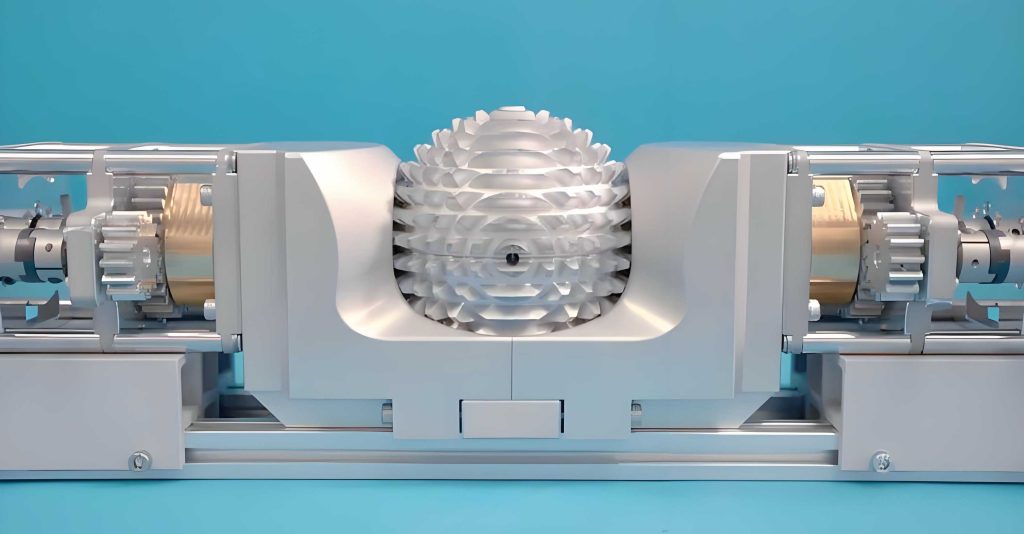
In the realm of modern machinery, gear transmission stands as one of the most critical mechanisms, with centuries of development behind it. Traditional gears, such as cylindrical, conical, and non-cylindrical types, have served well in transmitting rotation between parallel, intersecting, or skew axes with fixed relative positions. However, as technology advances, particularly in fields like robotics, biomimetics, and aerospace, there arises a need for mechanisms that can accommodate multi-degree-of-freedom movements. This is where the concept of spherical gear transmission comes into play. I have embarked on a comprehensive study to explore spherical gear传动, aiming to overcome inherent limitations and develop a robust theoretical framework alongside practical modeling techniques. The spherical gear, a novel member of the gear family, offers two degrees of freedom, enabling the transmission of two-dimensional rotational motion—a capability essential for applications like omnidirectional bionic joints, flexible robot wrists, and humanoid robotic hips and shoulders. This article delves into the传动 theory, design principles, and computer-aided modeling of spherical gears, with a focus on an annular involute surface spherical gear mechanism that addresses previous shortcomings.
My investigation begins with an overview of related research. The spherical gear emerged from studies on robot flexible wrists in the early 1980s, notably with inventions like the “spherical crown gear” by engineers, which used discrete pits and conical fingers for啮合. While such designs allowed omnidirectional deflection, they suffered from significant传动 errors at larger angles, often exceeding 15%, due to fundamental啮合原理 flaws. Various institutions, including哈尔滨工业大学 and清华大学, attempted improvements through modifications like single-tooth designs or specialized fixtures, but these only offered partial solutions. The core issues lay in the discrete distribution of teeth on the spherical surface and the齿廓 curve selection. To eliminate these原理 errors, I propose a continuous annular involute surface for the spherical gear, which ensures precise传动比 transmission and simplifies manufacturing. This approach transforms the spherical gear from a niche component into a viable option for high-precision applications.
To establish a common understanding, I define key术语 associated with spherical gears. These terms are crucial for后续 analysis and are summarized in the table below.
| Term | Definition |
|---|---|
| Polar Axis | A line through the sphere center perpendicular to the gear ring plane, serving as the rotation axis during machining. |
| Gear Ring | The annular body formed by revolving a planar gear profile around the polar axis. |
| Convex Gear | A spherical gear with teeth at the polar axis end, resembling a cylindrical回转体. |
| Concave Gear | A spherical gear with a recess at the polar axis end, forming a concave回转体. |
| Tip Sphere | The sphere generated by revolving the addendum circle of the planar gear around the polar axis. |
| Root Sphere | The sphere generated by revolving the dedendum circle of the planar gear around the polar axis. |
| Pitch Sphere | The sphere generated by revolving the pitch circle of the planar gear around the polar axis. |
| Base Sphere | The sphere generated by revolving the base circle of the planar gear around the polar axis. |
| 啮合锥 | The set of contact points during spherical gear啮合, forming a conical surface. |
These definitions underpin the geometric and kinematic analysis of spherical gears. For instance, in a spherical gear mechanism, two spherical gears interact via their pitch spheres in pure rolling motion, allowing relative偏摆 of their polar axes in any direction. This unique characteristic stems from the齿廓 formation原理, which I elaborate next.
The齿廓 of the spherical gear is derived from an annular involute surface. Consider a planar gear pair in engagement, with their centers aligned along the polar axis. By revolving this planar pair 360° around the polar axis, we obtain a pair of spherical gears. The齿廓曲面 is generated as follows: Let a generating line roll without slip on a base circle within a plane that itself rotates around the polar axis. As the generating line moves, any point on it traces out a path that forms the齿廓曲面 of the spherical gear. Mathematically, this can be expressed using parametric equations. For a point on the generating line at a distance \( r \) from the base circle center, the coordinates in a spherical system are given by:
$$ x = R_b \cos(\theta) + r \cos(\phi) \sin(\theta) $$
$$ y = R_b \sin(\theta) – r \cos(\phi) \cos(\theta) $$
$$ z = r \sin(\phi) $$
where \( R_b \) is the base sphere radius, \( \theta \) is the rotation angle around the polar axis, and \( \phi \) is the pressure angle variable. This生成 process ensures that in any cross-section containing the polar axis, the tooth profile is an involute curve. Thus, the spherical gear齿廓 is a continuous环形渐开面, enabling smooth啮合 across all orientations. This design fundamentally resolves the issues of discrete teeth and improper齿廓 curves in earlier spherical gear variants.
The啮合 characteristics of spherical gears are distinct from conventional gears. During transmission, the two pitch spheres undergo pure rolling, resulting in point contact between the齿廓s at all times, except when the polar axes coincide, where contact forms a circular ring. This point contact is sufficient for motion transmission due to the kinematic constraints. The啮合 points always lie in a common plane that contains the polar axes and is normal to the齿廓 surfaces. Consequently, the locus of啮合 points constitutes two oppositely oriented锥面, enhancing the omnidirectional capability. The传动比 remains constant and is determined by the ratio of the numbers of teeth on the two spherical gears, similar to spur gears. For a pair of spherical gears, the instantaneous传动比 \( i \) is given by:
$$ i = \frac{\omega_1}{\omega_2} = \frac{z_2}{z_1} $$
where \( \omega_1 \) and \( \omega_2 \) are angular velocities, and \( z_1 \) and \( z_2 \) are the tooth numbers. This holds true regardless of the relative orientation of the polar axes, provided the正确啮合条件 are met.
The正确啮合条件 for spherical gears are derived from their equivalence to spur gears in the normal plane. Each spherical gear has an equivalent spur gear, referred to as the “equivalent gear,” whose parameters match the normal-plane parameters of the spherical gear. Therefore, for proper啮合, the following conditions must be satisfied:
- The normal module \( m_n \) must be equal for both spherical gears: \( m_{n1} = m_{n2} \).
- The normal pressure angle \( \alpha_n \) must be equal: \( \alpha_{n1} = \alpha_{n2} \).
- Additionally, for pairing, one spherical gear must be convex (with polar axis through the tooth center) and the other concave (with polar axis through the tooth space center).
These conditions ensure continuous and smooth motion transmission. The parameters can be summarized in a table for clarity.
| Parameter | Symbol | Condition for Correct啮合 |
|---|---|---|
| Normal Module | \( m_n \) | \( m_{n1} = m_{n2} \) (standard values) |
| Normal Pressure Angle | \( \alpha_n \) | \( \alpha_{n1} = \alpha_{n2} \) (typically 20°) |
| Gear Type | — | Convex paired with concave |
Furthermore, the重合度 of spherical gears, which indicates the number of tooth pairs in contact simultaneously, is calculated similarly to spur gears. The formula for重合度 \( \epsilon \) is:
$$ \epsilon = \frac{1}{2\pi} \left[ z_1 (\tan \alpha_{a1} – \tan \alpha’) + z_2 (\tan \alpha_{a2} – \tan \alpha’) \right] $$
where \( z_1 \) and \( z_2 \) are the tooth numbers of the two spherical gears, \( \alpha_{a1} \) and \( \alpha_{a2} \) are the tip pressure angles, and \( \alpha’ \) is the operating pressure angle. A higher重合度 ensures smoother传动 and load distribution. For standard spherical gears, I recommend designing for \( \epsilon > 1.2 \) to avoid intermittent contact.
In terms of manufacturing, spherical gears can be produced using生成 methods analogous to those for spur gears, but with an added rotation around the polar axis. However, this process may lead to undercutting or根切 when the tooth number is too low. To prevent this,变位修正 can be applied. By shifting the cutting tool relative to the gear blank, we obtain modified spherical gears with变位 coefficients. The minimum tooth number to avoid根切 in spherical gears is the same as for spur gears, given by:
$$ z_{\text{min}} = \frac{2h_a^*}{\sin^2 \alpha_n} $$
where \( h_a^* \) is the addendum coefficient. For standard parameters (\( \alpha_n = 20° \), \( h_a^* = 1 \)), \( z_{\text{min}} \approx 17 \). If the actual tooth number is less, a positive变位 coefficient \( x \) can be used, calculated as:
$$ x = \frac{z_{\text{min}} – z}{z_{\text{min}}} $$
This变位修正 not only avoids根切 but can also optimize the tooth shape for strength and wear resistance. The impact of变位 on spherical gear performance is an area I plan to explore further in future work.
Moving to computer-aided modeling, constructing accurate digital models of spherical gears is essential for simulation, analysis, and offline programming. I have developed a method based on rotational sweep造型, which is ideal for generating回转体 like spherical gears. The algorithm involves discretizing the base profile (an involute curve) and revolving it around the polar axis to form a 3D surface. Below, I outline the steps in this旋转扫掠造型法.
- Define the Base Profile: Generate the involute curve for a single tooth in the normal plane, using parametric equations. Discretize this curve into a sequence of points \( P_0, P_1, \dots, P_n \).
- Create Point Chains: Arrange these points in order to form a closed chain representing the tooth profile.
- Specify Rotation Axis: Set the polar axis as the rotation axis, typically along the z-axis in a Cartesian coordinate system.
- Revolve Points: For each point in the chain, rotate it around the polar axis through a full 360° with a small angular increment \( \Delta \theta \). This generates a set of vertices for each rotation step.
- Form Vertex Tables: Link the rotated points to create a mesh of vertices. For example, after rotating point \( P_i \), we obtain a vertex table \( V_i \). Connect adjacent tables to form环链.
- Generate Micro-Facets: Between consecutive vertex tables, create triangular or quadrilateral facets to define the surface. Ensure right-hand rule ordering for consistent normals.
- Assemble Surface: Connect all micro-facets to form the complete tooth surface. Repeat for all teeth around the sphere.
- Smooth and Render: Apply smoothing algorithms (e.g., Phong shading) to enhance visual realism, and render the spherical gear model.
This method effectively constructs spherical gear models that can be used in CAD software for further analysis. The computational complexity depends on the discretization level, but modern systems handle it efficiently. To illustrate, the key parameters for modeling are summarized in the table below.
| Modeling Parameter | Description | Typical Value/Range |
|---|---|---|
| Number of Teeth (z) | Total teeth on the spherical gear | 20 to 50 |
| Normal Module (m_n) | Module in the normal plane | 1 mm to 5 mm |
| Pressure Angle (α_n) | Angle in normal plane | 20° |
| Sphere Radius (R) | Radius of the pitch sphere | Derived from m_n and z |
| Angular Increment (Δθ) | Step for rotation in modeling | 1° to 5° |
| Discretization Points | Points per involute segment | 100 to 500 |
Using this algorithm, I have created detailed spherical gear models that facilitate啮合 simulation and performance evaluation. For instance, the传动 model can be analyzed for contact stresses and kinematic accuracy under various loading conditions. The spherical gear design proves particularly advantageous in applications requiring multi-axis rotation, such as robotic wrists or satellite antennas, where traditional gears fall short.
In conclusion, spherical gear transmission represents a significant advancement in gear technology, offering two degrees of freedom and omnidirectional motion capability. Through my research, I have established a foundational theory for annular involute surface spherical gears, addressing previous limitations in离散齿 distribution and齿廓 design. The正确啮合条件,重合度 calculations, and变位修正 methods are directly applicable from spur gear theory, simplifying design processes. Moreover, the rotational sweep modeling algorithm enables efficient digital representation, crucial for modern engineering workflows. The potential applications of spherical gears are vast, extending beyond柔性手腕 to include bionic joints, prosthetics, aerospace姿态 control systems, and advanced robotics. Future work should focus on areas like tooth strength optimization, efficiency analysis, material selection, and precision manufacturing techniques to fully realize the benefits of spherical gears. As this field evolves, spherical gears may become as ubiquitous as cylindrical gears in specialized机械 systems, driven by their unique kinematic properties. This study underscores the importance of continuous innovation in传动 mechanisms to meet emerging technological demands.
Throughout this article, I have emphasized the spherical gear concept, exploring its传动 principles and modeling approaches. The spherical gear, with its annular involute surface, offers a robust solution for precise multi-axis motion transmission. By integrating theoretical insights with practical modeling techniques, I aim to contribute to the growing body of knowledge on spherical gears, paving the way for their broader adoption in engineering applications. The journey of spherical gear development is just beginning, and I look forward to further investigations that will unlock new possibilities in机械 design and automation.