
The pursuit of higher performance in precision reducers for industrial robots is a continuous engineering challenge. While conventional RV reducers and harmonic drives dominate the market, there remains significant potential for structural innovation to enhance key metrics such as transmission accuracy, efficiency, and load capacity. This work presents the development and comprehensive analysis of a novel compact cycloidal drive, or more specifically, an abnormal cycloidal planetary reducer. The design builds upon established transmission principles but introduces a distinct two-stage architecture aimed at improving performance indicators. The development process encompassed detailed three-dimensional modeling, rigorous force and strength analysis, theoretical efficiency calculation, multi-body dynamics simulation, and ultimately, prototype fabrication and testing. This narrative details the entire journey from conceptual design to experimental validation, demonstrating the feasibility and performance characteristics of the proposed cycloidal drive mechanism.
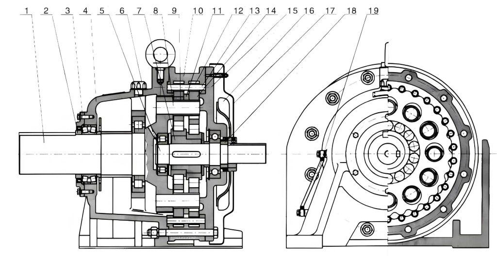
The proposed cycloidal drive operates on a two-stage reduction principle. The primary stage is a standard planetary gear train with a sun gear, planetary gears, and a fixed ring gear. The secondary stage, which is the core innovation, employs an abnormal cycloidal pinwheel mechanism. The power flow initiates at the input sun gear, which drives the planetary gears. These planetary gears, in turn, cause the planet carrier to rotate. The planet carrier is rigidly connected to an eccentric shaft. The rotation of this eccentric shaft drives a pair of identical abnormal cycloidal gears, which mesh with a set of stationary needle rollers housed in the casing. The cycloidal gears then drive the output disk via pins, completing the power transmission. This configuration offers high reduction ratios in a compact envelope, a hallmark of advanced cycloidal drive systems.
The initial design phase involved defining the key technical parameters for the cycloidal drive to meet a target specification, notably a rated output torque of 180 N·m. The selected parameters are summarized in Table 1.
| Technical Parameter | Value | Technical Parameter | Value |
|---|---|---|---|
| Total Transmission Ratio, i | 273 | Number of Needle Rollers in Casing, zj | 40 |
| Module, m (mm) | 1.25 | Diameter of Needle Rollers, dj (mm) | 5 |
| Meshing Pressure Angle, α’ (°) | 20 | Distribution Circle Diameter of Holes on Cycloidal Gear, dlfc (mm) | 92.6 |
| Sun Gear Teeth, z1 | 12 | Width of Cycloidal Gear, blc (mm) | 9 |
| Planetary Gear Teeth, z2 | 30 | Eccentricity, e (mm) | 1 |
| Ring Gear Teeth, z3 | 72 | Distribution Circle Radius of Casing Needles, rj (mm) | 50.5 |
| Number of Needle Rollers on Cycloidal Gear, zlc | 39 | Rated Torque, T (N·m) | 180 |
Based on these parameters, the total transmission ratio for this cycloidal drive is calculated as:
$$ i = \left( \frac{z_2}{z_1} \times \frac{z_3}{z_2} + 1 \right) \left( \frac{z_{lc}}{z_j – z_{lc}} \right) = 273 $$
The materials selected for critical components are crucial for strength and durability. The choice of materials and their properties are listed in Table 2.
| Component | Material | Elastic Modulus (MPa) | Poisson’s Ratio | Density (kg/m³) |
|---|---|---|---|---|
| Housing | 40Cr | 2.12×10⁵ | 0.277 | 7870 |
| Sun Gear | 40Cr | 2.12×10⁵ | 0.277 | 7870 |
| Planetary Gears | 40Cr | 2.12×10⁵ | 0.277 | 7870 |
| Planet Carrier & Eccentric Shaft | GCr15 | 2.19×10⁵ | 0.3 | 7830 |
| Cycloidal Gears & Pins | GCr15 | 2.19×10⁵ | 0.3 | 7830 |
A full three-dimensional assembly model was created using SolidWorks software, incorporating all components such as gears, the planet carrier, eccentric shafts, cycloidal gears, needle rollers, and bearings. This model served as the digital twin for subsequent analysis and guided the detailed design of individual parts for manufacturing.
The force analysis within the cycloidal drive is fundamental for ensuring structural integrity. The analysis is divided into the two main stages: the involute gear stage and the cycloidal pinwheel stage.
For the first-stage planetary gear train, with the ring gear fixed and the planet carrier as output, the input torque $T_1$ required at the sun gear is derived from the output torque $T_H$ at the carrier. Considering the stage transmission ratio $i_{1H}=7$ and an assumed efficiency $\eta=0.9$, the input torque is:
$$ T_1 = \frac{T_H}{i_{1H} \eta} $$
Given $T_H = 4.62 \text{ N·m}$, we find $T_1 = 0.73 \text{ N·m}$. The tangential force $F_t$ and radial force $F_r$ between the sun gear and a planetary gear are:
$$ F_{t21} = \frac{2 T_1}{3 m z_1}, \quad F_{r21} = F_{t21} \tan \alpha’ $$
Calculating these values yields $F_{t21} = 32.44 \text{ N}$ and $F_{r21} = 11.81 \text{ N}$. The resultant normal meshing force $F_{n12}$ is:
$$ F_{n12} = \sqrt{F_{t21}^2 + F_{r21}^2} = 34.52 \text{ N} $$
The sun gear, being the smallest component, was checked for both contact and bending strength according to standard gear design formulas. The contact stress $\sigma_H$ and allowable contact stress $\sigma_{HG}$ were evaluated. The core calculation for contact stress is:
$$ \sigma_H = \sigma_{H0} \sqrt{K_A K_V K_{H\alpha} K_{H\beta}}, \quad \text{where} \quad \sigma_{H0} = Z_H Z_E Z_{\varepsilon} \sqrt{ \frac{F_{t21}}{d_1 b} \frac{u+1}{u} } $$
The bending stress $\sigma_F$ and allowable bending stress $\sigma_{FA}$ were also calculated:
$$ \sigma_F = \sigma_{F0} K_A K_V K_{F\beta} K_{F\alpha}, \quad \text{where} \quad \sigma_{F0} = \frac{F_{t21}}{b m} Y_{Fa} Y_{Sa} Y_{\varepsilon} $$
The results confirmed that the calculated stresses were significantly lower than the allowable limits, validating the gear design for the intended cycloidal drive application.
The force analysis for the cycloidal drive stage is more complex due to the multi-tooth engagement of the cycloidal gear with the stationary needle rollers. The force distribution among the engaged pins is not uniform. The maximum force $F_{max}$ on a pin occurs at the point farthest from the line of action of the output torque. Based on the geometry of the cycloidal drive, this force can be expressed as:
$$ F_{max} = \frac{2.2 T}{k_1 r_j z_{lc}} $$
where $k_1$ is the cycloidal gear’s shortening coefficient, $r_j$ is the distribution radius of the casing needles, $z_{lc}$ is the number of pins on the cycloidal gear, and $T$ is the output torque. For a single cycloidal gear assumed to carry 55% of the total load ($T_C = 0.55T$), with $T=180 \text{ N·m}$, $k_1 \approx 0.917$, $r_j=50.5 \text{ mm}$, and $z_{lc}=39$, the maximum pin force is $F_{max} = 254.51 \text{ N}$.
The contact stress $\sigma_{Hn}$ between a cycloidal gear pin and a casing needle roller, modeled as two cylinders in contact, is calculated using the Hertzian formula:
$$ \sigma_{Hn} = 0.418 \sqrt{ \frac{E_c}{b_c} \frac{F_i}{\rho_i} } $$
Here, $E_c$ is the composite elastic modulus, $b_c$ is the length of the pin, $F_i$ is the force on the i-th pin (with $F_{max}$ being the highest), and $\rho_i$ is the pin radius (2.5 mm). The calculated maximum contact stress was approximately 465 MPa, which is well below the allowable contact stress for GCr15 bearing steel (typically 1200 MPa), confirming the durability of the cycloidal drive’s core engagement.
To virtually validate the kinematic and dynamic performance of the cycloidal drive design, a multi-body dynamics simulation was conducted using Adams software. The detailed 3D model was imported, and appropriate joints (fixed, revolute), contacts, and a step-drive function were applied to the input sun gear. The simulation aimed to analyze transmission ratio, meshing forces, and efficiency.
The angular velocities of the input sun gear, the planet carrier (first-stage output), and the final output disk were obtained from the simulation. The average simulated values closely matched the theoretical calculations, as shown in Table 3. The small relative error of 0.41% for the total ratio confirms the correctness of the cycloidal drive’s kinematic design.
| Component | Theoretical Value (°/s) | Simulation Average (°/s) | Relative Error (%) |
|---|---|---|---|
| Sun Gear (Input) | 9000 | 9000 | 0 |
| Planet Carrier | 1285.83 | 1278.64 | 0.56 |
| Output Disk | 32.97 | 33.10 | 0.39 |
The meshing forces were also simulated. The normal force between the sun gear and a planetary gear averaged 32.57 N, and between a planetary gear and the ring gear averaged 33.16 N, both aligning well with the theoretical value of 34.52 N. For the cycloidal drive stage, the simulated average meshing force was 250.76 N, closely matching the calculated $F_{max}$ of 254.51 N.
The theoretical transmission efficiency $\eta$ of the entire cycloidal drive unit was calculated by considering the efficiencies of both stages and the bearings. The planetary stage efficiency $\eta_{Hc}$ and the cycloidal stage efficiency $\eta_{Hl}$ are given by:
$$ \eta_{Hc} = 1 – \pi \mu \left( \frac{1}{z_1} + \frac{1}{z_2} + \frac{1}{z_3} \right) \times \left( \varepsilon_1^2 + \varepsilon_2^2 + \varepsilon_3^2 + 1 – \varepsilon_1 – \varepsilon_2 – \varepsilon_3 \right) $$
$$ \eta_{Hl} = 1 – \frac{\mu_c c}{k_1} \left(1 – \frac{r_{lc}}{r_j} \right) $$
where $\mu$ and $\mu_c$ are friction coefficients, and $c$ is a sliding coefficient. The combined efficiency for the cycloidal drive, accounting for the power flow, is:
$$ \eta = \frac{ (i_{lH} – 1)(i_{lH} – \eta_{Hl} – i_{1H} i_{lH} \eta_{Hc}) }{ (i_{lH} – \eta_{Hl})(i_{lH} – 1 – i_{1H} i_{lH}) } \eta_b $$
With typical friction coefficients ($\mu=0.1$, $\mu_c=0.06$) and bearing efficiency $\eta_b=0.98$, the theoretical total efficiency was calculated to be 92.39%. An Adams efficiency simulation, applying the 0.73 N·m input torque and measuring the output torque, yielded a simulated efficiency of 91.42%, showing good agreement with the theoretical model for this cycloidal drive.
Following the design and simulation phases, a physical prototype of the cycloidal drive was manufactured. Key components like the cycloidal gears with precision pin holes, eccentric shafts, and gears were machined using processes such as gear hobbing, gear shaping, drilling, and grinding, followed by heat treatment for wear resistance. The components were carefully assembled to create the functional prototype unit.
The prototype was tested on a dedicated precision reducer test platform equipped with high-resolution encoders and torque sensors. The primary performance indicators measured were transmission error and transmission efficiency, which are critical for any high-performance cycloidal drive.
Transmission error, defined as the difference between the theoretical and actual output angle for a given input, was measured over multiple revolutions. The error curves for both forward and reverse rotation were recorded. The peak-to-peak transmission error was found to be approximately 103.4 arcseconds for forward operation and 107.4 arcseconds for reverse operation.
Transmission efficiency was measured by loading the output from zero to the rated torque. The efficiency curves showed a maximum efficiency of 82.34% in forward operation and 81.62% in reverse operation under rated conditions. These experimental values, while lower than the theoretical and simulated predictions (primarily due to manufacturing imperfections and assembly preloads), represent a viable result for a first-generation prototype of a novel cycloidal drive.
The performance of the developed cycloidal drive prototype was benchmarked against the national standard (GB/T 37718-2019) for comparable domestic RV-20E type reducers. A comparative summary is presented in Table 4.
| Performance Indicator | National Standard for RV-20E | Developed Cycloidal Drive Prototype | Assessment |
|---|---|---|---|
| Transmission Error (Peak-to-Peak) | ≤ 70 arcseconds | ~103 arcseconds | Close to, but slightly above standard. Further optimization is needed. |
| Transmission Efficiency | ≥ 80% | 82.34% | Meets and slightly exceeds the standard requirement. |
In conclusion, the development and analysis of this novel abnormal cycloidal planetary reducer, or cycloidal drive, demonstrate a feasible and promising alternative architecture for robotic applications. The force analysis and strength checks confirmed the structural soundness of the design. Dynamic simulations accurately predicted kinematic behavior and meshing forces, aligning well with theoretical models. Although the prototype’s transmission error requires further refinement through improved manufacturing precision and component optimization, its measured transmission efficiency successfully meets the benchmark standard. This work validates the core transmission principle and provides a solid foundation for the continued development of high-performance, compact cycloidal drive units aimed at enhancing the capabilities of industrial robotics.