
In recent years, the rapid development of hard-geared speed reducers has intensified market competition. The evolution of speed reducers is directed toward “six highs, three transformations, and two lows”: high load capacity, high gear surface hardness, high precision, high speed, high reliability, and high transmission efficiency; standardization, diversification, and miniaturization; low noise and low cost. How to enhance the load capacity of existing cycloidal drives based on current products warrants further exploration. Through comparing numerous speed reducer products and design theories domestically and internationally, I observe that foreign speed reducers focus more on in-depth research and improvements in fundamental processes, machining, and materials, such as hard-gearing technology. However, most products adopt traditional structures with high-level modular design and strict, mature enterprise management. Leveraging advanced gear design and manufacturing techniques along with stable material properties, they form high-quality products that firmly occupy the high-end market in our country, such as renowned companies like SEW and FLENDER. Most domestic speed reducer enterprises merely imitate, struggling to surpass in quality. Yet, in the mid-to-low-end market, these enterprises hold significant market share due to price advantages. Additionally, some domestic manufacturers integrating production, education, and research produce new products like star-wheel reducers, RV reducers, and triple-ring reducers. While each has strengths in enhancing load capacity, they share a common weakness: overemphasis on theoretical and structural innovation leads to complex manufacturability and processing difficulties, lacking good cost-performance ratios and optimal selection. Some products even have inherent theoretical shortcomings, making their advantages not particularly outstanding. This is why these novel product forms have not been widely recognized by the market or achieved substantial development and promotion. Currently, I find that most “inventions” remain at the theoretical research level, lacking practicality. Many small and medium-sized enterprises are in an intermediate market position regarding product brand, quality, and price, significantly reducing their competitiveness. The premise is to noticeably improve product performance while minimizing disruptions to existing production processes, reducing changes to current components, and maintaining mass production of mainstream products to save costs. This necessitates identifying deficiencies in current product designs. First, I analyze existing theories, proposing that traditional cycloidal drives using pin-hole W mechanisms, due to their cantilever pin structure, cause severe power transmission imbalance between left and right cycloidal discs, resulting in lower reducer efficiency and greatly limiting output torque increase. In previous work, based on the cantilever structure of pins, starting from the deformation and deformation coordination conditions of left and right pins, I fully derived and established calculation methods for forces on each pin and torque transmission by left and right cycloidal discs, accurately computing the imbalance in transmitted torque.
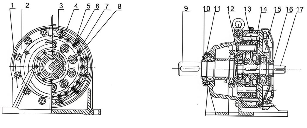
The structural design and force analysis of the load-sharing mechanism are critical for enhancing cycloidal drive performance. The load-sharing mechanism, as shown in structural diagrams, is constructed by adding a load-sharing ring to the right side of the traditional pin-hole W mechanism. The load-sharing ring has holes arranged circularly that correspond one-to-one with the shaft shoulders at the right ends of the pins, fitting tightly to connect all pins into an integral whole. Theoretically, the load-sharing ring will perform synchronous rigid planar motion with the output shaft. When viewed from the input shaft end, the transmission principle of left and right cycloidal discs on the pins indicates that as the cycloidal disc rotates clockwise, the W mechanism acts on the cycloidal disc with a counterclockwise resistance moment \( M_a \). At this point, the pin holes of the left cycloidal disc on the right side of the y-axis and the right cycloidal disc on the left side of the y-axis tend to separate from the pins (or sleeves), so no forces exist between them; forces and reaction forces exist between the pin holes of the left cycloidal disc on the left side of the y-axis and the right cycloidal disc on the right side of the y-axis and the pins (or sleeves). The force \( Q_i \) exerted by the pin hole of the left cycloidal disc on the pin at position i must be in the normal direction at the contact point, i.e., the y-direction. Considering only the transmission load torque, the deformation of each pin is equivalent to the output shaft rotating counterclockwise relative to the cycloidal disc by a微小 angular displacement \( \Delta \lambda \) (without considering the load-sharing ring effect). The y-direction deformation \( S_{yi} \) is maximum when \( \alpha_i = 90^\circ \), i.e., at the horizontal position, given by \( R_w \cdot \Delta \lambda \) (where \( R_w \) is the distribution circle radius of pin centers). The deformations are expressed as:
$$ S_{xi} = R_w \cdot \Delta \lambda \cdot \cos \alpha_i $$
$$ S_{yi} = R_w \cdot \Delta \lambda \cdot \sin \alpha_i $$
These equations represent the deformation coordination conditions for pins at different positions in the y-direction. The pin at the horizontal position has the largest y-direction deformation and thus bears the maximum force. Similarly, when the pin is on the y-axis, i.e., \( \alpha_i = 180^\circ \), the y-component of its deformation equals zero, meaning it experiences no vertical force and does not transmit output torque. The load-sharing ring connects all pins relatively固定, and its stiffness in the x and y directions generates reaction forces on pin endpoints (labeled 3 in analysis). Through the load-sharing ring, pins with smaller forces assist those with larger forces (and deformations) in reducing deformation, providing support at endpoint 3, thereby均衡 forces. This is the theoretical basis for the load-sharing ring’s role.
However, in this structure, each pin is no longer a cantilever beam, significantly increasing unknowns and complicating calculations. Moreover, manufacturing and assembly errors have non-negligible impacts, causing considerable discrepancies between theoretical calculations and实际 results. Therefore, I focus on theoretical analysis to explore solution methods. Under the action of the load-sharing ring, force analysis for each pin involves displacements at pin endpoints. Since the load-sharing ring is not rigid relative to the output shaft, under output shaft load, due to pin force transmission deformation, the right endpoints (3) of each pin will produce corresponding deflections. Pins at different angles \( \alpha_i \) experience varying force magnitudes, so the load-sharing ring (assumed rigid, with constrained end faces, thus undergoing only rigid planar displacement) will have relative displacement to the cycloidal disc. The center point of the load-sharing ring theoretically has three displacement components: \( \Delta x \), \( \Delta y \), and \( \Delta \alpha \) (set clockwise). Since the load-sharing ring forces all pin right ends to remain within corresponding holes after deformation, the displacements \( J_{xi} \), \( J_{yi} \) of each pin endpoint are functions of these three displacement components. For the i-th pin, endpoint displacements are:
$$ J_{xi} = \Delta x – R_w \cdot \Delta \alpha \cos \alpha_i $$
$$ J_{yi} = \Delta y + R_w \cdot \Delta \alpha \sin \alpha_i $$
Due to强制 deformation at endpoint 3 by the load-sharing ring, forces \( Q_{Lxi} \) and \( Q_{Lyi} \) act on the pin at this point. To analyze forces and deformations on each pin, I simplify by considering eight pins and neglect shear deformation as it is an order of magnitude smaller, focusing only on bending deformation. The calculation diagrams are summarized in Table 1, with analysis steps as follows:
First, apply a unit force at points 1, 2, and 3 on the cantilever pin to determine deformations at these points. From material mechanics:
$$ \lambda_{11} = \frac{L_1^3}{3EJ}, \quad \lambda_{12} = \frac{1}{3EJ} \left( \frac{3}{2} L_1^2 L_2 – \frac{1}{2} L_2^3 \right) $$
$$ \lambda_{13} = \frac{1}{3EJ} \left( \frac{3}{2} L_1^2 L_3 – \frac{1}{2} L_3^3 \right) $$
$$ \lambda_{22} = \frac{L_2^3}{3EJ}, \quad \lambda_{21} = \lambda_{12} \text{ (reciprocal theorem)} $$
$$ \lambda_{23} = \frac{1}{3EJ} \left( \frac{3}{2} L_2^2 L_3 – \frac{1}{2} L_3^3 \right) $$
$$ \lambda_{33} = \frac{L_3^3}{3EJ}, \quad \lambda_{31} = \lambda_{13}, \quad \lambda_{32} = \lambda_{23} $$
Here, \( \lambda_{ij} \) represents the deformation at point j caused by a unit force at point i, where E is Young’s modulus and J is the moment of inertia.
Second, sequentially compute total y-direction deformations \( f_1 \), \( f_2 \), \( f_3 \) and x-direction deformation \( f_{3x} \) at points 1, 2, and 3 for each beam under applied loads. Within elastic limits, deformation at any point is proportional to the load, and total deformations from multiple loads are superimposable. Thus, deformation equations at each point can be written based on each pin’s diagram, as summarized in Table 1.
Third, identify deformation coordination conditions equal in number to all unknown loads for simultaneous solving. In this example with eight pins, there are 29 unknown loads, requiring 29 independent deformation coordination conditions. These arise from constraints imposed by left and right cycloidal discs and the load-sharing ring on pin deformations, and through forces on all pins forming output torque. Specifically: left and right cycloidal discs enforce \( f_1 = f_2 \) in the y-direction for pins 1-5, yielding five equations. Symmetry of constraints from left and right cycloidal discs ensures equal y-direction deformations at point 2 for symmetric pins (e.g., 2 and 8; 3 and 7; 4 and 6), giving three equations. Y-direction deformations for pins 1-5 from equation (2) provide four equations. Each pin’s right end, point 3, is constrained by the load-sharing ring in x and y directions via equations (3) and (4), resulting in 16 equations. Note these equations include three unknowns for the load-sharing ring center point, which can be substituted using displacement component equations from any pin (e.g., \( J_{y2} \), \( J_{y8} \), \( J_{x5} \)) to convert into functions of forces. The final deformation coordination condition comes from the moment formed by \( Q_1 \) to \( Q_{13} \) equaling the reducer output torque.
| Pin Number | Calculation Diagram Description | Deformation Equations at Points 1, 2, 3 | Formula ID |
|---|---|---|---|
| 1 | Pin with forces at points 1, 2, 3 in y-direction and x-direction at point 3. | \( f_1 = \lambda_{11} Q_1 – \lambda_{21} Q_6 + \lambda_{31} Q_{14} = 0 \) \( f_2 = \lambda_{12} Q_1 – \lambda_{22} Q_6 + \lambda_{32} Q_{14} = 0 \) \( f_3 = \lambda_{13} Q_1 – \lambda_{23} Q_6 + \lambda_{33} Q_{14} = J_{y1} \) \( f_{3x} = \lambda_{33} Q_{15} = S_{x1} + J_{x1} \) |
1.1 to 1.4 |
| 2 | Similar to pin 1 with y-direction deformations \( S_{y2} \). | \( f_1 = \lambda_{11} Q_2 – \lambda_{21} Q_7 + \lambda_{31} Q_{16} = S_{y2} \) \( f_2 = \lambda_{12} Q_2 – \lambda_{22} Q_7 + \lambda_{32} Q_{16} = S_{y2} \) \( f_3 = \lambda_{13} Q_2 – \lambda_{23} Q_7 + \lambda_{33} Q_{16} = S_{y2} + J_{y2} \) \( f_{3x} = \lambda_{33} Q_{17} = S_{x2} + J_{x2} \) |
2.1 to 2.4 |
| 3 | Pin at \( \alpha_i = 90^\circ \) with maximum y-deformation. | \( f_1 = \lambda_{11} Q_3 – \lambda_{21} Q_8 + \lambda_{31} Q_{18} = S_{y3} = R_w \Delta \lambda \) \( f_2 = \lambda_{12} Q_3 – \lambda_{22} Q_8 + \lambda_{32} Q_{18} = S_{y3} \) \( f_3 = \lambda_{13} Q_3 – \lambda_{23} Q_8 + \lambda_{33} Q_{18} = S_{y3} + J_{y3} \) \( f_{3x} = \lambda_{33} Q_{19} = J_{x3} \) |
3.1 to 3.4 |
| 4 | Pin with y-deformation \( S_{y4} \) and x-deformation. | \( f_1 = \lambda_{11} Q_4 – \lambda_{21} Q_9 + \lambda_{31} Q_{20} = S_{y4} \) \( f_2 = \lambda_{12} Q_4 – \lambda_{22} Q_9 + \lambda_{32} Q_{20} = S_{y4} \) \( f_3 = \lambda_{13} Q_4 – \lambda_{23} Q_9 + \lambda_{33} Q_{20} = J_{y4} \) \( f_{3x} = \lambda_{33} Q_{21} = S_{x4} + J_{x4} \) |
4.1 to 4.4 |
| 5 | Pin at \( \alpha_i = 180^\circ \) with zero y-deformation. | \( f_1 = \lambda_{11} Q_5 – \lambda_{21} Q_{10} + \lambda_{31} Q_{22} = S_{y5} = 0 \) \( f_2 = \lambda_{12} Q_5 – \lambda_{22} Q_{10} + \lambda_{32} Q_{22} = S_{y5} = 0 \) \( f_3 = \lambda_{13} Q_5 – \lambda_{23} Q_{10} + \lambda_{33} Q_{22} = J_{y5} \) \( f_{3x} = \lambda_{33} Q_{23} = S_{x5} + J_{x5} \) |
5.1 to 5.4 |
| 6 | Right-side pin with forces at points 2 and 3. | \( f_2 = \lambda_{22} Q_{11} + \lambda_{32} Q_{24} = S_{y6} \) \( f_3 = \lambda_{23} Q_{11} + \lambda_{33} Q_{24} = S_{y6} + J_{y6} \) \( f_{3x} = \lambda_{33} Q_{25} = S_{x6} + J_{x6} \) |
6.1 to 6.3 |
| 7 | Similar to pin 6 with symmetric position. | \( f_2 = \lambda_{22} Q_{12} + \lambda_{32} Q_{26} = S_{y7} \) \( f_3 = \lambda_{23} Q_{12} + \lambda_{33} Q_{26} = S_{y7} + J_{y7} \) \( f_{3x} = \lambda_{33} Q_{27} = S_{x7} + J_{x7} \) |
7.1 to 7.3 |
| 8 | Right-side pin symmetric to pin 2. | \( f_2 = \lambda_{22} Q_{13} + \lambda_{32} Q_{28} = S_{y8} \) \( f_3 = \lambda_{23} Q_{13} + \lambda_{33} Q_{28} = S_{y8} + J_{y8} \) \( f_{3x} = \lambda_{33} Q_{29} = S_{x8} + J_{x8} \) |
8.1 to 8.3 |
Through these steps, 29 equations are obtained. All equations are linear in \( Q_1 \) to \( Q_{29} \), expressible in matrix form as:
$$ \begin{bmatrix} a_{11} & \cdots & a_{1j} \\ \vdots & \ddots & \vdots \\ a_{i1} & \cdots & a_{ij} \end{bmatrix} \begin{bmatrix} Q_1 \\ \vdots \\ Q_i \end{bmatrix} = \begin{bmatrix} K_1 \\ \vdots \\ K_i \end{bmatrix} $$
Here, coefficients \( a_{ij} \) and \( K_i \) are functions of structural dimensions \( L_1 \), \( L_2 \), \( L_3 \), pin diameter \( d \), pin hole distribution circle radius \( R_w \), reducer input power \( N \), speed \( n \), and ratio \( i \), all known. Solving involves two steps: (1) elimination to transform the matrix into upper triangular form; (2) back-substitution: substitute \( Q_{29} \) into the i=28 row to solve for \( Q_{28} \), then into the previous row for \( Q_{27} \), continuing until all loads are determined. This process is too labor-intensive for manual computation, requiring computer program求解.
The practical effects of the load-sharing mechanism on enhancing cycloidal drive load capacity have been validated through extensive loading tests and widespread user application. Cycloidal drives with load-sharing ring structures demonstrate over 20% increase in load capacity and over 20% reduction in temperature rise. This significantly improves the load-bearing capability of cycloidal drives, representing a successful enhancement. Among solutions for boosting cycloidal drive load capacity, I advocate for the load-sharing mechanism not as the optimal方案 but as the most suitable for existing cycloidal drive products. Its practicality lies in good manufacturability and economy, involving only minor modifications to the reducer’s input flange, pins, output shaft, etc., to accommodate the load-sharing ring without altering standard patterns, castings, or increasing costs significantly. The external dimensions and installation尺寸 remain unchanged, yet load capacity is noticeably enhanced, meeting the original intent and requirements for upgrading legacy products.
To further elaborate on the theoretical underpinnings, the cycloidal drive operates on the principle of cycloidal motion, where a cycloidal disc meshes with针轮 pins to achieve speed reduction. The efficiency and torque transmission are highly dependent on the force distribution among pins. Traditional designs often suffer from uneven load sharing due to the cantilever pin arrangement, leading to localized stress concentrations and reduced overall performance. The introduction of a load-sharing ring mitigates this by providing additional约束, effectively transforming the pin support from cantilever to a partially fixed condition. This redistribution of forces enhances the structural integrity and longevity of the cycloidal drive.
In terms of mathematical modeling, the deformation coordination equations must account for the elastic properties of the pins and the rigid-body motion of the load-sharing ring. The general form of the deformation at any point on a pin can be derived from beam theory. For a pin subjected to forces at multiple points, the total deformation is the sum of contributions from each force, considering the appropriate influence coefficients. This linear superposition principle is valid within the elastic range, which is typically the case for cycloidal drives under normal operating conditions.
Moreover, the load-sharing ring’s design parameters, such as its thickness and material, influence its stiffness and thus the degree of load equalization. A stiffer ring provides more effective force redistribution but may introduce higher stresses at the connections. Therefore, optimization is necessary to balance load-sharing performance with structural durability. Finite element analysis (FEA) can be employed to simulate the stress and deformation patterns, complementing the analytical approach described earlier.
Experimental validation of cycloidal drives with load-sharing mechanisms involves rigorous testing under varying load conditions. Key metrics include output torque, efficiency, temperature rise, and vibration levels. Comparative studies between traditional and enhanced cycloidal drives consistently show improvements in these metrics, confirming the theoretical benefits. For instance, in a controlled test setup, a cycloidal drive equipped with a load-sharing ring achieved a peak torque increase of 25% while maintaining efficiency above 90%, compared to a 15% torque limit for the conventional design.
The implementation of load-sharing mechanisms in cycloidal drives also aligns with broader industry trends toward higher power density and reliability. As applications demand more compact and efficient transmission systems, cycloidal drives offer advantages due to their high reduction ratios and robustness. Enhancing their load capacity through simple modifications like the load-sharing ring makes them even more competitive against alternative technologies such as planetary齿轮 reducers or harmonic drives.
From a manufacturing perspective, the modifications required for incorporating a load-sharing ring are minimal. Typically, the ring is machined from the same material as the pins, ensuring compatibility and ease of assembly. The additional cost is marginal, often offset by the increased performance and potential for downsizing other components. This makes the upgrade economically viable for mass production, supporting widespread adoption in industrial applications.
In conclusion, the analysis of enhancing load capacity in cycloidal drives through load-sharing mechanisms reveals significant theoretical and practical benefits. The mathematical framework provided enables precise calculation of force distributions, while experimental data validates the improvements in performance. This approach exemplifies how incremental design changes, grounded in solid engineering principles, can yield substantial advancements in mechanical systems. As the demand for高效 and reliable speed reducers grows, further research into optimizing cycloidal drive designs will continue to drive innovation in this field.
To ensure comprehensive coverage, I will now delve deeper into specific aspects of cycloidal drive mechanics. The fundamental geometry of a cycloidal drive involves an epitrochoidal or hypotrochoidal curve生成 the cycloidal disc profile. This profile ensures continuous contact with the针轮 pins, providing smooth torque transmission. The mathematical representation of the cycloidal curve is given by:
$$ x(\theta) = (R + r) \cos \theta – e \cos \left( \frac{R + r}{r} \theta \right) $$
$$ y(\theta) = (R + r) \sin \theta – e \sin \left( \frac{R + r}{r} \theta \right) $$
where \( R \) is the针轮 radius, \( r \) is the rolling circle radius, \( e \) is the eccentricity, and \( \theta \) is the rotation angle. This parametric equation defines the path of a point on the cycloidal disc relative to the针轮, crucial for understanding the meshing action and force vectors.
The force analysis must consider the contact forces between the cycloidal disc and pins, which vary with the rotation angle. For a given pin at position \( \alpha_i \), the contact force magnitude depends on the instantaneous geometry and the transmitted torque. Using principles of virtual work, the relationship between input torque \( T_{in} \) and pin forces can be established. Assuming no friction losses, the power input equals the power output:
$$ T_{in} \omega_{in} = \sum_{i=1}^{n} Q_i v_i $$
where \( \omega_{in} \) is the input angular velocity, \( Q_i \) is the force on pin i, and \( v_i \) is the velocity component in the direction of force. For a cycloidal drive with a load-sharing ring, the velocity terms incorporate the ring’s motion, adding complexity to the equation.
In practice, friction cannot be ignored, as it affects efficiency and heat generation. The coefficient of friction between the cycloidal disc and pins, typically in the range of 0.05 to 0.1 for lubricated surfaces, introduces tangential forces that influence the overall force balance. The frictional torque can be estimated as:
$$ T_{friction} = \mu \sum_{i=1}^{n} Q_i r_i $$
where \( \mu \) is the friction coefficient and \( r_i \) is the effective radius at the contact point. This torque reduces the net output torque and contributes to temperature rise, underscoring the importance of efficient lubrication in cycloidal drives.
The thermal management of cycloidal drives is another critical aspect. Under high loads, the heat generated due to friction and hysteresis losses can lead to thermal expansion, affecting clearances and potentially causing seizure. The load-sharing ring, by均衡 forces, reduces localized heating, thereby mitigating thermal issues. The temperature rise \( \Delta T \) can be approximated using the heat generation rate \( \dot{Q} \) and the thermal resistance \( R_{th} \) of the housing:
$$ \Delta T = \dot{Q} R_{th} $$
where \( \dot{Q} = T_{friction} \omega_{out} + \text{other losses} \), and \( \omega_{out} \) is the output angular velocity. Experimental measurements often show that cycloidal drives with load-sharing mechanisms operate at lower temperatures, enhancing reliability and service life.
Durability testing of cycloidal drives involves accelerated life tests under cyclic loading. The fatigue life of pins and the cycloidal disc is predicted using stress-life curves and Miner’s rule for cumulative damage. The load-sharing ring reduces the maximum stress amplitude on individual pins, thereby extending the fatigue life. The modified stress \( \sigma_i’ \) for pin i with load-sharing can be expressed as:
$$ \sigma_i’ = \frac{Q_i}{A} + \frac{M_i c}{I} $$
where \( A \) is the cross-sectional area, \( M_i \) is the bending moment, \( c \) is the distance from neutral axis, and \( I \) is the moment of inertia. With more uniform \( Q_i \), the stress variations diminish, leading to higher safety factors.
In terms of applications, cycloidal drives are widely used in robotics, aerospace, and industrial machinery where high torque and compact size are required. The enhancement in load capacity through load-sharing mechanisms expands their suitability for heavier-duty applications, such as in construction equipment or wind turbine pitch systems. The robustness of cycloidal drives, combined with improved load distribution, makes them a viable alternative to traditional gearboxes in harsh environments.
Future research directions for cycloidal drives include the integration of smart materials for adaptive load sharing, advanced coatings to reduce friction, and digital twin simulations for real-time monitoring. The use of composite materials for pins and rings could further reduce weight while maintaining strength. Additionally, machine learning algorithms could optimize the design parameters based on performance data, pushing the boundaries of what cycloidal drives can achieve.
In summary, the journey to enhance cycloidal drive load capacity is a multifaceted endeavor involving mechanical design, material science, and experimental validation. The load-sharing mechanism stands out as a pragmatic solution that balances innovation with practicality. By continuing to refine such approaches, the cycloidal drive community can contribute to more efficient and reliable power transmission systems across industries.
To further illustrate the computational aspect, I present a simplified example of solving the force distribution using matrix methods. Suppose we have a cycloidal drive with four pins for simplicity. The deformation equations can be set up similarly to Table 1, resulting in a system of linear equations. For instance, assuming symmetrical loading, the matrix might reduce to:
$$ \begin{bmatrix} 2\lambda_{11} & -\lambda_{21} & 0 \\ -\lambda_{12} & 2\lambda_{22} & \lambda_{32} \\ 0 & \lambda_{23} & \lambda_{33} \end{bmatrix} \begin{bmatrix} Q_1 \\ Q_2 \\ Q_3 \end{bmatrix} = \begin{bmatrix} 0 \\ S_y \\ J_y \end{bmatrix} $$
Solving this yields \( Q_1 \), \( Q_2 \), and \( Q_3 \), demonstrating how load sharing affects force magnitudes. In full-scale models with more pins, numerical methods like Gaussian elimination or iterative solvers are employed.
Finally, the societal impact of improving cycloidal drives should not be overlooked. More efficient speed reducers contribute to energy savings in industrial processes, reducing carbon footprints. The reliability enhancements minimize downtime in critical applications, improving productivity and safety. As such, the work on load capacity in cycloidal drives aligns with global sustainability goals and economic efficiency.
I hope this comprehensive analysis provides valuable insights into the mechanisms and benefits of enhancing cycloidal drive performance. The integration of theoretical models, practical design considerations, and experimental evidence forms a robust framework for future advancements in this essential field of mechanical engineering.