
In my extensive experience with mechanical transmission systems, I have found that the cycloidal drive stands out as a remarkably efficient and compact solution for a wide range of industrial applications. This type of speed reducer, often referred to simply as a cycloidal drive, is prized for its high reduction ratio, smooth operation, and durability in demanding environments such as chemical processing, mining, and medical equipment. However, to fully harness its advantages, a deep understanding of its operation, proper installation, meticulous usage, and proactive maintenance is essential. Through this article, I aim to share a comprehensive, first-hand perspective on the cycloidal drive, delving into its fundamental principles and systematically analyzing the common challenges encountered throughout its lifecycle. I will employ detailed explanations, formulas, and structured tables to encapsulate key knowledge, ensuring that practitioners can optimize performance and extend service life effectively.
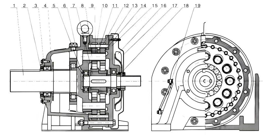
The core functionality of a cycloidal drive is rooted in planetary gear theory, but it utilizes a unique kinematic principle based on the meshing between a cycloidal disc (or lobe) and a ring of stationary pin gears. In my analysis, I break down the mechanism into three primary components: the input section, the reduction section, and the output section. These form an integrated assembly that is typically characterized by a small footprint and high structural density. The input shaft is equipped with a double eccentric cam assembly, often arranged 180 degrees out of phase. This cam assembly, housed within a set of rolling bearings known as the arm or turntable bearings, creates an H-shaped configuration. The cycloidal discs, which have a lobed profile, are mounted on these eccentric cams and engage with the stationary pin gears housed in the casing. The magic lies in the tooth difference: this engagement creates a single-stage, high-ratio reduction through a so-called “cycloidal” or “hypocycloidal” motion.
To quantify the reduction, the fundamental formula for the reduction ratio (i) of a standard single-stage cycloidal drive is given by:
$$ i = -\frac{Z_p}{Z_p – Z_c} $$
where \( Z_p \) represents the number of pin gears (or teeth in the stationary ring) and \( Z_c \) represents the number of lobes on the cycloidal disc. The negative sign typically indicates a reversal in the direction of rotation between input and output. For instance, if a cycloidal disc has \( Z_c = 39 \) lobes and meshes with \( Z_p = 40 \) pin gears, the reduction ratio is:
$$ i = -\frac{40}{40 – 39} = -40 $$
This means for every 40 revolutions of the input shaft, the output shaft completes one revolution in the opposite direction. This high ratio in a single stage is a hallmark of the cycloidal drive’s design efficiency.
The motion dynamics are fascinating to observe. As I have tested and verified, when the input shaft rotates, it drives the eccentric cams. This imparts a compound motion to the cycloidal discs: a combination of revolution (around the central axis) and rotation (about their own center). For each full clockwise rotation of the input, the eccentricity causes the cycloidal disc to “walk” or roll counterclockwise against the fixed pins by a distance of one pin space. This slow, reverse rotation is then transmitted through an output mechanism, often a pin-slot or wobble plate arrangement, to the output shaft, resulting in the significant speed reduction. The contact between the cycloidal disc lobes and the pin gears (often via needle roller bearings or pin sleeves) is primarily rolling rather than sliding, which contributes to the high mechanical efficiency and smooth operation that makes the cycloidal drive so reliable.
Moving from theory to practice, the installation phase is critical for ensuring the long-term health of any cycloidal drive. Based on my field observations, improper installation is a leading cause of premature failure. The compact size of the cycloidal drive, while advantageous for integration, demands precision during mounting. The following table consolidates the most frequent installation issues I have encountered, along with their root causes and recommended corrective actions.
| Issue Category | Typical Manifestation & Root Cause | Preventive & Corrective Measures |
|---|---|---|
| Axial Load on Output Shaft | Direct hammering or impact force applied during coupling installation. The output shaft’s axial thrust capacity is limited. Using the shaft end thread to forcibly pull a coupling can cause bearing brinelling or shaft bending. | Always use the shaft end thread properly by screwing in a bolt to press-fit the coupling. Never apply direct hammer blows to any part of the cycloidal drive housing or shaft. Use appropriate assembly tools and hydraulic presses if necessary. |
| Misalignment | Poor concentricity and angular alignment between the cycloidal drive and the driven/driving machine. This induces excessive radial and bending loads. | Precisely align the centerlines and ensure the mounting surfaces are level. Use dial indicators or laser alignment tools. The allowable misalignment tolerance is often very small for a cycloidal drive; consult the manufacturer’s specification. Employ shims under the base for precise leveling. |
| Lubrication System Setup | Neglecting to connect or configure an external oil pump system if the application requires forced lubrication. Ingress of contaminants during installation. | Before startup, verify all lubrication lines are connected, clean, and free of leaks. For oil-bath lubricated units, ensure the correct grade and quantity of oil is filled as per the environmental operating temperature range. |
| Mounting Rigidity and Frame Distortion | Mounting the cycloidal drive on an uneven or weak base, or tightening foundation bolts unevenly. This can distort the housing, affecting gear mesh and bearing alignment. | Ensure the foundation is robust and flat. Tighten mounting bolts in a criss-cross pattern to a uniform torque specification. Use properly sized and symmetrically arranged support pads. |
| Excessive Inclination Angle | Installing the cycloidal drive at an angle beyond its design limit, leading to improper oil distribution and potential oil leakage from seals. | Maintain the installation angle strictly within the manufacturer’s limit, typically not exceeding 15 degrees from the horizontal plane. For vertical shaft applications, use models specifically designed for such orientation. |
Once a cycloidal drive is correctly installed, its operational life is heavily influenced by daily usage parameters. The drive is generally designed for continuous, bi-directional service, but certain boundaries must be respected. From my troubleshooting sessions, I have cataloged a pattern of usage-related problems that often stem from overlooking basic operational guidelines. The voltage supply to the driving motor, load characteristics, and especially lubrication management are recurring themes. The table below provides a systematic overview.
| Operational Factor | Problem Description & Consequences | Best Practices & Solutions |
|---|---|---|
| Electrical Supply | Operating the drive motor outside its rated voltage range (under-voltage or over-voltage). This can cause motor overheating, reduced torque, and increased slip, indirectly overloading the cycloidal drive. | Ensure a stable power supply within the motor’s nameplate specifications. Use voltage regulators or soft starters if line fluctuations are common. Monitor motor current during operation. |
| Overloading | Subjecting the cycloidal drive to radial or axial loads exceeding its catalog rating, or to shock loads. This accelerates wear on pins, cycloidal disc lobes, and bearings. | Always size the cycloidal drive with an adequate service factor for the application. Use external supports (e.g., pillow blocks) if high overhung loads are present. Avoid abrupt starts and stops; consider controlled acceleration. |
| Lubrication Oil Selection | Using the wrong viscosity or type of lubricant for the ambient temperature. High oil temperature (>90°C) can lead to oxidation, loss of lubricity, and accelerated bearing failure. | Select an ISO VG grade oil recommended by the manufacturer for the expected operating temperature range. For extreme temperatures, synthetic oils may be necessary. The relationship between viscosity (ν), temperature (T), and performance can be conceptualized by models like the Vogel equation for temperature dependence. |
| Oil Level Management | Running the cycloidal drive with insufficient oil (causing poor lubrication and overheating) or overfilling (causing churning losses, overheating, and seal leakage). | Regularly check the oil level via sight glass or dipstick, maintaining it at the exact center mark. For a cycloidal drive with an oil sump, the approximate oil volume \( V \) can be estimated based on housing dimensions, but always follow the manual. A simple check formula during maintenance is to ensure the oil covers the lowest rotating component when stationary. |
| Oil Change Intervals | Extending oil change intervals beyond what is suitable for the operating environment. Contaminated or degraded oil leads to abrasive wear. | Perform the first oil change after the initial 100-200 hours of run-in. Subsequently, change oil every 6-12 months for normal service. In harsh environments (high dust, moisture, temperature), shorten the interval to 3-6 months. Always clean the magnetic plug and housing interior during oil changes. |
| Thermal Monitoring | Ignoring elevated housing temperature. Excessive heat is a symptom of overload, poor lubrication, or internal damage. | Regularly monitor the housing temperature with an infrared thermometer or permanently mounted sensor. The maximum allowable temperature for bearings often dictates the limit. If temperature rises abnormally, investigate immediately. |
Even with impeccable installation and operation, a cycloidal drive, like any precision mechanical system, requires scheduled maintenance to uncover and rectify wear before it leads to catastrophic failure. My involvement in repair workshops has highlighted several key components that are prone to wear and specific procedural pitfalls during overhaul. A proactive maintenance strategy for a cycloidal drive should combine periodic inspections with timely component replacement. I categorize these aspects into two streams: routine checks and detailed repair actions, as summarized in the following comprehensive table.
| Maintenance Activity | Critical Components & Common Issues | Inspection Criteria & Repair Protocol |
|---|---|---|
| Periodic Inspection (Visual & Functional) | Fasteners and Couplings: Looseness due to vibration. | Check all mounting bolts, coupling bolts, and shaft keys for secure tightness using a torque wrench. Verify coupling alignment remains within tolerance. |
| Oil Condition and Leakage: Degraded oil, water ingress, seal leaks. | Sample oil for analysis. Visually inspect for discoloration, metallic particles, or milky appearance (water). Check all seals (output shaft, input shaft, housing joints) for leaks. | |
| Unusual Noise and Vibration: Indicative of internal wear or misalignment. | Listen for changes in operational sound. Use vibration analysis tools to detect frequencies associated with bearing defects (e.g., arm bearings) or gear mesh issues. | |
| Output Rotation and Backlash: Excessive free play. | Manually rock the output shaft to feel for excessive angular backlash. Compare to baseline or manufacturer’s spec. Increased backlash often points to wear in the cycloidal disc lobes, pin gears, or output pin holes. | |
| Detailed Repair & Overhaul | Shaft Seals: Lip seals harden, crack, or wear, allowing contamination. | Replace shaft seals during every major overhaul. Ensure the shaft sealing surface is smooth and free of scratches. Use the correct seal size and material for the lubricant. |
| Eccentric Bearings (Arm Bearings): High dynamic loads cause fatigue spalling or clearance increase. | These are critical wear items. Replace eccentric bearings preemptively if signs of roughness or increased radial play are detected. Proper installation with correct fits is vital. | |
| Cycloidal Discs and Pin Gears/Sleeves: Lobe wear, pitting, or breakage; pin sleeve scoring. | Inspect lobed surfaces for pitting, spalling, or polishing. Check pin sleeves for grooves or excessive clearance. Replace worn sets as matched pairs from the same manufacturer to maintain precise geometry. The wear depth \( \delta \) on a lobe can be measured and compared to a rejection limit. | |
| Output Mechanism (Wobble Plate, Pins, Housings): Wear on pins, slots, or the thrust washer surfaces. | Inspect for fretting, galling, or dimensional wear. The output pins should be round and fit snugly in the cycloidal disc holes. Replace worn components. The surface hardness of the wobble plate and spacer washers is crucial for long life. | |
| Gaskets and Sealing Surfaces: Oil leaks from housing joints post-disassembly. | Thoroughly clean mating surfaces. Always use a new gasket or apply a suitable liquid sealant per manufacturer’s instruction. Ensure bolt torque sequence is followed. | |
| Component Mixing: Using parts from different cycloidal drive models or manufacturers. | This is a cardinal error. Tolerances and heat treatments are model-specific. Always use genuine replacement parts or certified equivalents from the original manufacturer to ensure proper meshing and load distribution. |
Beyond the checklist approach, my reflections on chronic problems with cycloidal drives lead to deeper engineering considerations. Many failures are systemic, originating from design selection or external factors rather than the drive itself. For instance, a persistent issue of overheating might not be solved by changing oil alone; it could indicate that the cycloidal drive is undersized for the application’s torque and duty cycle. The required torque \( T_{req} \) should always be less than the rated torque \( T_{rated} \) of the drive with an appropriate service factor \( SF \):
$$ T_{req} \times SF \leq T_{rated} $$
Another subtle point is the effect of start-up inertia. High inertia loads started too rapidly can induce shock torques that far exceed the drive’s momentary peak rating, potentially causing tooth impact damage on the cycloidal disc lobes. In such cases, an external soft-start system for the motor is not just beneficial but necessary for protecting the cycloidal drive.
The quality of lubrication cannot be overstated. I have seen cycloidal drives fail prematurely simply due to the use of a lubricant with poor extreme pressure (EP) additives or one that has been contaminated with abrasive particles. The wear rate of the pin sleeves and cycloidal discs can be modeled in a simplified manner related to contact stress and lubrication film thickness, governed by equations like the Hertzian contact stress formula for cylindrical surfaces:
$$ \sigma_{H} = \sqrt{\frac{F}{2\pi} \cdot \frac{E_{eq}}{R_{eq}}} $$
where \( F \) is the normal load, \( E_{eq} \) the equivalent elastic modulus, and \( R_{eq} \) the equivalent radius of curvature. Maintaining a proper elastohydrodynamic lubrication (EHL) film minimizes this stress and wear.
Furthermore, the design and material properties of ancillary parts like the spacer washers and the output wobble plate are critical. Their surface hardness (\( H \)) and roughness (\( R_a \)) directly influence frictional losses and wear in the output mechanism. During repair, verifying that these components meet the original specifications for hardness (e.g., Rockwell C scale) and have a low surface roughness is as important as replacing the main gears. A mismatch here can lead to rapid wear even with new cycloidal discs and pins.
In conclusion, the reliable and efficient operation of a cycloidal drive is a multifaceted endeavor that begins with understanding its elegant yet precise working principle. From my hands-on experience, I emphasize that success hinges on a disciplined approach across all phases: precision installation respecting alignment and load limits, vigilant operation within electrical and thermal boundaries with meticulous lubrication management, and a proactive maintenance regimen that includes regular inspections and the use of correct, matched components during repairs. The cycloidal drive, with its unique combination of compactness and high reduction ratio, is a robust workhorse when treated with the engineering care it deserves. By internalizing the insights and structured guidelines presented here—through formulas quantifying its performance and tables cataloging its failure modes—practitioners can significantly enhance the productivity and longevity of these remarkable mechanical reducers, ensuring they deliver their full potential across countless industrial applications.