
Throughout my extensive career in industrial maintenance and engineering, particularly within sectors like cotton processing, material handling, and general manufacturing, I have consistently encountered and relied upon various减速机. Among these, the cycloidal drive has emerged as a standout performer. Its unique operating principle, combining high reduction ratios with remarkable compactness and durability, has made it a preferred choice for demanding applications. This article consolidates my firsthand knowledge and practical insights into the use, installation, lubrication, and maintenance of cycloidal drives. I aim to provide a comprehensive resource that goes beyond basic manuals, incorporating lessons learned from the field to ensure optimal performance and longevity of these drives.
The fundamental operation of a cycloidal drive hinges on a planetary mechanism employing cycloidal disc motion. Unlike traditional gear systems, it utilizes an eccentric cam to induce orbital movement in cycloidal discs, which then mesh with stationary pin gears (针齿). This action provides smooth, high-torque output with minimal backlash. The kinematic relationship governing its speed reduction is critical. For a standard single-stage cycloidal drive, the reduction ratio \( i \) can be expressed as:
$$ i = \frac{N_p}{N_p – N_d} $$
Where \( N_p \) is the number of pins in the stationary ring gear and \( N_d \) is the number of lobes on the cycloidal disc. Typically, \( N_d = N_p – 1 \), leading to high reduction ratios in a compact package. This elegant principle is what赋予s the cycloidal drive its distinctive advantages.
The versatility of the cycloidal drive is one of its strongest attributes. In my work, I have successfully deployed these units across a diverse spectrum of industries. Their ability to handle shock loads and provide precise motion makes them indispensable. The following table summarizes key application areas and the corresponding benefits offered by the cycloidal drive technology.
| Industry Sector | Typical Applications | Primary Benefits of Cycloidal Drive |
|---|---|---|
| Material Handling & Lifting | Conveyor systems, hoists, crane drives, palletizers. | High overhung load capacity, excellent shock absorption, reliable positioning. |
| Mining & Mineral Processing | Crushers, screens, feeders, slurry pumps. | Robust construction for harsh environments, high torque density, resistance to contamination. |
| Chemical & Petrochemical | Mixers, agitators, extruder drives, pump drives. | Smooth operation for sensitive processes, compact size for limited spaces, durability. |
| Food, Beverage & Pharmaceutical | Packaging machinery, filling lines, processing conveyors. | Cleanability (with appropriate seals), low maintenance intervals, hygienic design options. |
| Textile & Cotton Processing | Ginning machinery, bale presses, lint cleaners, conveyor drives. | Resistance to fibrous dust ingress, consistent speed under variable load, long service life with proper care. |
| General Manufacturing | Machine tools, indexing tables, robotic actuators. | High precision, low backlash, compact design for integration into automated systems. |
Selecting and operating a cycloidal drive correctly requires strict adherence to its designed parameters. Based on my observations, most premature failures can be traced back to violations of these basic conditions. The允许d input speed is a crucial factor. While many standard cycloidal drive models are rated for input speeds around 1500 to 1800 RPM, the optimal range for power transmission above 18.5 kW often centers on 1500 RPM to balance heat generation and mechanical stress. Exceeding these limits can lead to excessive wear on the cycloidal discs and bearings. The drive’s orientation is another key consideration. Although designed for horizontal mounting, limited倾斜 is sometimes unavoidable. The maximum permissible tilt angle \( \theta_{max} \) without special provisions is generally 15°. Beyond this, lubrication becomes problematic. The effective oil level in the sump changes, potentially starving critical components. For angles greater than 15°, I recommend using auxiliary lubrication systems or specially designed housings. The output shaft is not intended to sustain substantial external radial or axial loads. The maximum allowable external force can be estimated considering the bearing specifications. For instance, the equivalent dynamic radial load \( P_r \) should satisfy:
$$ P_r = XF_r + YF_a \leq C_{dynamic} $$
Where \( F_r \) is the applied radial force, \( F_a \) is the applied axial force, \( X \) and \( Y \) are bearing factors, and \( C_{dynamic} \) is the basic dynamic load rating of the output bearing. When external forces are significant, external support via pillow blocks or coupling designs that absorb these forces is mandatory for protecting the cycloidal drive.
| Parameter | Standard Condition / Limit | Notes & Recommendations |
|---|---|---|
| Operating Duty Cycle | Continuous (S1) | Suitable for 24/7 operation; allows bidirectional rotation. |
| Standard Input Speed (RPM) | 1500 – 1800 | For powers >18.5 kW, 1500 RPM is preferred to manage thermal load. |
| Mounting Position | Horizontal (Standard) | Base mounting feet should be fully supported. |
| Maximum Tilt Angle (Standard) | 15° | Beyond this, requires special lubrication arrangement. |
| Ambient Temperature Range | -10°C to +40°C | For extremes, consult manufacturer for oil grade and sealing options. |
| Output Shaft Loading | Minimal external radial/axial force | Use couplings that isolate loads; calculate forces against bearing ratings. |
Proper lubrication is the lifeblood of any cycloidal drive. Neglect here is the fastest route to catastrophic failure. The standard method is oil bath lubrication, where the oil level should be maintained at the center of the sight glass. The oil volume \( V_{oil} \) for a given housing size can be approximated from the gearbox dimensions. For a rough estimate, if the housing is considered a rectangular prism, \( V_{oil} \approx L \times W \times h_{oil} \), where \( h_{oil} \) is the desired oil height. In harsh environments with high ambient temperatures or dusty conditions, a forced circulation (oil-mist or spray) system is advisable to ensure adequate cooling and particle flushing. The choice of lubricant is critical. I exclusively use high-quality extreme pressure (EP) gear oils with anti-wear additives. The required viscosity grade is a function of operating temperature and speed. A general guideline for initial selection at an average operating temperature \( T_{op} \) (in °C) is to choose an ISO VG oil where the viscosity at 40°C \( \nu_{40} \) meets:
$$ \log(\nu_{40}) \approx 3.0 – 0.02 \times (T_{op} – 20) \quad \text{(for mineral oils)} $$
For example, at 40°C, an ISO VG 220 or 320 oil is common for industrial cycloidal drives. The oil change interval is not arbitrary. It depends on operating hours, load factor, and environmental cleanliness. As a rule of thumb, for standard conditions (8-16 hours/day, clean environment), the first oil change should occur after the initial 100-200 hours of operation to remove wear-in particles. Subsequent changes for continuous operation should be every 2500-4000 hours or every 6 months, whichever comes first. In severe service, such as in cotton processing with high dust levels, I advocate for shortening this to 1500-2000 hours or every 3-4 months. The cost of oil is trivial compared to the cost of a failed cycloidal drive.
| Operational Context | Recommended Oil Type (ISO VG) | Initial Oil Change | Regular Change Interval | Check/Topping Frequency |
|---|---|---|---|---|
| General Industry, Moderate Load | EP Gear Oil, ISO VG 220 | After 200 hours | 4000 hours or 12 months | Weekly visual check |
| Heavy-Duty, High Temperature (>50°C) | Synthetic EP Oil, ISO VG 320 | After 100 hours | 2500 hours or 6 months | Twice weekly |
| Harsh/Dusty (e.g., Cotton Ginning) | EP Gear Oil with Detergents, ISO VG 220 | After 150 hours | 1500-2000 hours or 3-4 months | Daily check if possible |
| Vertical Mount Configuration | As per horizontal, but ensure pump function | Same as horizontal | Same or 20% shorter interval | Daily check of oil level and pump |
Correct installation sets the stage for reliable performance. I cannot overstate the importance of precision during this phase. The process begins with preparing a rigid, level foundation. When placing the cycloidal drive, never lift it using the output shaft or input adapter; always use the dedicated lifting eye(s). Aligning the drive with the prime mover and the driven machine is paramount. Misalignment induces parasitic forces that dramatically shorten bearing life. For direct coupling, the allowable parallel and angular misalignment should typically be less than 0.05 mm and 0.05° respectively, as per coupling specifications. Laser alignment tools provide the best accuracy. Shim selection under the base is an art. Use steel or cast iron shims, and never more than three shims under any foot. The total shim pack height \( H_{shim} \) should correct for foundation unevenness \( \Delta H \). Arrange them symmetrically around anchor bolts to avoid distorting the housing. After alignment, grout the baseplate thoroughly using non-shrink cementitious grout to ensure full contact and dampen vibrations. The grout compressive strength \( f’_c \) should exceed 5000 psi after curing. Finally, when connecting elements to the output shaft (coupling hub, pulley, sprocket), never hammer them on. Use the threaded puller holes on the shaft end and a press or tightening bolts to draw the component on smoothly. The fit should be a transition fit, typically H7/js6 or similar, to ensure a secure connection without excessive stress.
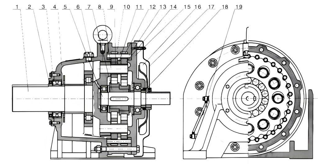
Even the most robust cycloidal drive will eventually require maintenance. Through systematic troubleshooting, I’ve identified common failure modes. Bearing failure is the most frequent, often signaled by increased noise, vibration, or heat. The primary bearings supporting the eccentric cam and the output shaft bearings are typical culprits. Seal failure leading to oil leakage or ingress of contaminants is another common issue. Occasionally, the output shaft may fracture due to unexpected shock loads or severe misalignment. Input motor failures, while not intrinsic to the cycloidal drive itself, are often associated with the drive system. A proactive maintenance approach involves regular vibration analysis and thermography. For instance, monitoring the vibration velocity \( v_{rms} \) in mm/s can provide early warning. An increase beyond baseline by a factor of 2 often indicates developing issues. When disassembly is necessary, I have developed a methodical approach that saves considerable time. After draining the oil and removing the housing bolts, I carefully extract the entire internal assembly. To reassemble the cycloidal disc and pin assembly correctly: First, ensure the eccentric bearings are in good condition. Then, orient the cycloidal discs. Each disc has a marking (often a number or dot). The key is to install them with their marked sides facing the same direction (usually toward the input side) and to align the lobes of one disc with the troughs of the other—this is the phase relationship essential for smooth load distribution. A 180° offset is standard for two-disc designs. This precise alignment ensures balanced forces and optimal performance of the cycloidal drive.
| Fault Mode | Primary Symptoms | Root Cause Analysis | Corrective Action & Parts |
|---|---|---|---|
| Bearing Failure (Eccentric/Output) | Excessive noise (grinding, rumbling), localized heat, increased vibration频谱 at bearing frequencies. | Fatigue due to overloading, lubricant failure (wrong type, low level, contamination), improper installation (preload). | Replace all bearings as a set. Clean housing thoroughly. Verify lubrication system. Bearing numbers are specific to cycloidal drive model. |
| Oil Leakage | Oil seepage from shaft seals, joint faces, or breather. | Worn/damaged shaft seals, damaged O-rings/gaskets, overfilling, clogged breather causing pressure buildup. | Replace seals and gaskets. Check breather. Ensure correct oil level. Use appropriate sealant on static faces if required. |
| Output Shaft Fracture | Sudden loss of drive, visible crack or break near shoulder or keyway. | Shock load exceeding material yield strength, fatigue from stress concentrator (poor keyway finish), severe misalignment. | Replace shaft. Analyze load history. Improve coupling design to absorb shocks. Ensure perfect alignment during reinstallation. |
| Increased Backlash / Reduced Precision | Noticeable play in output shaft, positioning errors. | Wear on cycloidal disc lobes or pin gear pins, bearing clearance increase. | Inspect discs and pins for wear. Replace worn components. In severe cases, replace the entire cycloidal disc/pin assembly. |
| Overheating | Housing temperature >90°C above ambient, discoloration. | Overloading, insufficient lubrication (low level, high viscosity), excessive ambient temperature, internal friction from misassembly. | Check load against rating. Verify oil type, level, and cooling. Ensure internal components are assembled correctly (disc phasing). |
| Motor Tripping / Failure | Drive motor overload protector trips, motor burns out. | Cycloidal drive seized or binding, excessive load on machine, motor undersized, electrical issue. | First disconnect the cycloidal drive and check if it rotates freely by hand. Repair drive as needed. Recalculate load and motor power requirements. |
To further optimize the lifecycle of a cycloidal drive, I recommend implementing a predictive maintenance schedule. This involves recording key parameters over time. For example, tracking the input current \( I_{in} \) and output speed \( \omega_{out} \) can help calculate the approximate efficiency \( \eta \):
$$ \eta(t) = \frac{T_{out} \cdot \omega_{out}}{V_{in} \cdot I_{in} \cdot \text{Power Factor}} $$
A gradual decline in \( \eta(t) \) can indicate increasing internal losses due to wear. Additionally, understanding the torque requirements is essential. The required output torque \( T_{req} \) for an application can be derived from the driven machine’s needs. For instance, for a conveyor, \( T_{req} = F \times r \), where \( F \) is the belt tension force and \( r \) is the drive pulley radius. Selecting a cycloidal drive with a rated torque \( T_{rated} \) that exceeds \( T_{req} \) by a service factor \( SF \) (typically 1.5 to 2.0 for moderate shock loads) is prudent:
$$ T_{rated} \geq T_{req} \times SF $$
This ensures the cycloidal drive operates within its capacity, extending its service life. In conclusion, the cycloidal drive is a sophisticated and highly capable power transmission component. Its successful integration and operation depend on a deep understanding of its principles, respectful adherence to its operating limits, meticulous installation, disciplined lubrication practices, and proactive, informed maintenance. By treating the cycloidal drive not as a black box but as a system whose physics and wear mechanisms can be understood and managed, significant gains in reliability, uptime, and total cost of ownership can be achieved. The lessons I’ve shared, born from both successes and setbacks in the field, underscore that the longevity of a cycloidal drive is directly proportional to the care and knowledge invested in its upkeep.