
The reliable and efficient operation of laboratory-scale equipment is paramount in geological, metallurgical, and material science research. Among these, small ball mills, such as the model with a 350 mm diameter by 160 mm long drum, are indispensable for sample preparation through grinding and pulverization. A critical component governing the performance, cost, and maintainability of such equipment is its power transmission system. Traditionally, these systems have relied on custom-built multi-stage gear trains. However, this approach presents significant drawbacks, including complex manufacturing, heavy weight, high cost, and lengthy assembly times. This article explores a transformative redesign, replacing the conventional gearbox with a compact, high-efficiency cycloidal drive, also known as a cycloidal speed reducer. The integration of this standardized component results in a ball mill that is structurally simpler, lighter, more cost-effective, and mechanically superior.
Analysis of Conventional Ball Mill Drive Systems
A standard laboratory ball mill’s primary function is to rotate a drum containing the sample and grinding media at a specific, controlled speed. The typical operational parameters necessitate a significant reduction from the motor’s high rotational speed to the drum’s relatively low speed. For instance, a common specification involves a 1.1 kW motor operating at approximately 910 rpm, which must be reduced to a drum speed of around 63 rpm.
The traditional design addresses this need with a bespoke gear train system. This system usually consists of a two-stage reduction gearbox employing spur or helical gears. Due to spatial constraints within the machine’s frame, achieving the required high reduction ratio (approximately 14.5:1 in this case) with only two gear stages forces the selection of a motor with a lower base speed, such as a 6-pole motor. The entire assembly, comprising the motor, gearbox, shafts, and bearings, is both bulky and heavy.
The shortcomings of this traditional architecture are substantial:
- Complex Manufacturing: All gearbox components (gears, shafts, housings) are non-standard, requiring custom design, material procurement, machining, and heat treatment. This process is time-consuming and expensive.
- Heavy Weight and Large Volume: The cast or machined housing and the steel gears contribute significantly to the overall machine weight, affecting portability and structural support needs.
- Assembly and Maintenance Difficulty: Precise alignment of multiple gear stages is crucial for smooth operation and longevity. Disassembly for maintenance or repair is a complex task.
- Noise and Vibration: Gear meshing, especially with less-than-perfect manufacturing or alignment, can generate considerable noise and vibration, which is undesirable in a laboratory setting.
The following table summarizes the characteristics of the traditional drive system:
| Component | Characteristics | Disadvantages |
|---|---|---|
| Motor | 6-pole induction motor (e.g., ~910 rpm) | Higher cost compared to standard 4-pole motors. |
| Gearbox | Custom 2-stage reduction gear train. | Heavy, bulky, expensive to produce, requires precise alignment. |
| Overall System | High reduction ratio (~14.5:1) achieved in limited space. | Complex assembly, difficult maintenance, prone to noise. |
Fundamental Principles and Advantages of the Cycloidal Drive
The proposed solution leverages a cycloidal drive, a type of precision speed reducer based on the principle of cycloidal motion and high-precision conjugate action. Its operation is fundamentally different from traditional involute gear systems and offers a suite of compelling advantages ideal for redesigning compact machinery like a ball mill.
Working Principle and Kinematics
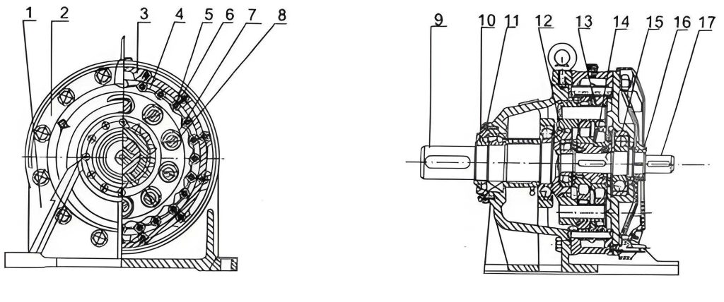
A single-stage cycloidal drive achieves high reduction ratios through a planetary configuration. The key components are:
- High-Speed Input Shaft: This shaft carries an eccentric cam or a set of eccentric bearings.
- Cycloidal Discs (or “Wheels”): Typically one or two discs with a lobed, cycloidal tooth profile. These discs are mounted on the eccentric bearing(s) on the input shaft.
- Stationary Ring Gear (Pin Wheel): A ring with a set of cylindrical pins (the “pin wheel”) that are stationary relative to the housing. The number of pins, \( N_p \), is usually one more than the number of lobes on the cycloidal disc, \( N_c \).
- Output Mechanism: A set of output pins or rollers housed in the output shaft that engage with holes in the cycloidal disc(s), converting the disc’s eccentric wobbling motion into concentric rotation of the output shaft.
The kinematic magic happens as follows: The input shaft’s rotation causes the eccentric bearing to orbit. The cycloidal disc, constrained by its meshing with the stationary pin wheel, cannot rotate freely. Instead, for each full orbit of the eccentric bearing (one revolution of the input shaft), the cycloidal disc is forced to rotate slightly in the opposite direction relative to the housing. This slight rotation is transmitted directly to the output shaft via the output pins.
The fundamental reduction ratio, \( i \), for a single-stage cycloidal drive is given by:
$$ i = \frac{N_p}{N_p – N_c} $$
Where \( N_p \) is the number of pins in the stationary ring and \( N_c \) is the number of lobes on the cycloidal disc. Since \( N_p – N_c = 1 \) in the most common design, the ratio simplifies dramatically to \( i = N_p \). For example, a disc with 40 lobes meshing with a ring of 41 pins yields a reduction ratio of 41:1 in a single, compact stage. This elegantly explains how such high ratios are achieved.
The motion transfer from the wobbling disc to the output shaft can be described by analyzing the relative motion. If \( \omega_{in} \) is the input angular velocity and \( \omega_{out} \) is the output angular velocity, then:
$$ \omega_{out} = \frac{\omega_{in}}{i} = \frac{\omega_{in}(N_p – N_c)}{N_p} $$
For the standard 1-tooth difference configuration, this becomes:
$$ \omega_{out} = \frac{\omega_{in}}{N_p} $$
Inherent Advantages for Mechanical Design
The cycloidal drive offers a combination of features that directly address the weaknesses of the traditional gearbox:
- Extremely High Single-Stage Reduction Ratio: As shown, ratios from about 6:1 to over 100:1 are possible in one stage, eliminating the need for multiple, space-consuming gear sets.
- Compact and Coaxial Design: The input and output shafts are concentric, leading to a very dense and space-efficient package. The overall volume and weight are a fraction of an equivalent gearbox.
- High Mechanical Efficiency and Torque Density: Due to rolling contact between the cycloidal disc and the pins (as opposed to the sliding contact dominant in involute gears), mechanical efficiencies often exceed 90%. The large number of teeth (lobes) in contact simultaneously (typically 1/3 to 1/2 of all lobes) distributes the load, allowing a small unit to transmit very high torque. Torque density (torque per unit volume/weight) is exceptional.
- Smooth and Quiet Operation: The multi-tooth engagement acts as a natural vibration damper, resulting in low noise and minimal torsional backlash.
- High Overload Capacity and Durability: Components are often made from hardened alloy steels (e.g., HRC 58-62), and the rolling-contact stress distribution provides excellent resistance to shock loads and ensures long service life.
- Standardization and Availability: Cycloidal drives are produced as standard, catalogued components in a wide range of sizes, ratios, and mounting configurations. This transforms them from a custom-made part into an off-the-shelf solution.
The comparative advantages are clearly laid out in the following table:
| Feature | Traditional Gearbox | Cycloidal Drive |
|---|---|---|
| Reduction Method | Multi-stage involute gears | Single-stage planetary cycloidal motion |
| Typical Single-Stage Ratio | 3:1 to 10:1 | 6:1 to 100+ |
| Size & Weight | Large, Heavy | Very Compact, Light |
| Efficiency | ~85-95% (per stage, compound losses) | ~90-94% (single stage) |
| Load Distribution | 1-2 tooth pairs in contact | Many lobes in simultaneous contact |
| Manufacturing | Custom, complex, costly | Standardized, off-the-shelf |
| Overload Resilience | Moderate | High (rolling contact, multi-lobe) |
Redesigning the Ball Mill with a Cycloidal Drive
Integrating a cycloidal drive into the XMQ350×160 ball mill fundamentally simplifies the drive train. The new configuration typically follows this path:
- Motor: A standard, cost-effective 4-pole AC induction motor (approx. 1430-1450 rpm) is selected.
- Cycloidal Drive (Reducer): The motor is directly flange-mounted to a suitably sized cycloidal drive. The reducer is selected to provide the necessary total reduction from motor speed to drum speed.
- Final Drive Stage: The output shaft of the cycloidal drive is connected to a small V-belt pulley. A V-belt transmits power to a larger pulley fixed to the ball mill drum, providing a final, fine-tuned speed adjustment and isolating some vibration.
The overall system reduction ratio, \( i_{total} \), is the product of the cycloidal drive ratio, \( i_{cyclo} \), and the belt drive ratio, \( i_{belt} \):
$$ i_{total} = i_{cyclo} \times i_{belt} = \frac{N_{motor}}{N_{mill}} $$
Where \( N_{motor} \) is the motor speed and \( N_{mill} \) is the desired drum speed.
Selection and Sizing Methodology for the Cycloidal Drive
Proper selection is critical for reliability. The process involves several key calculations based on the reducer manufacturer’s specifications. The primary selection criteria are based on output torque and thermal capacity (input power). Here is a detailed selection methodology:
Step 1: Determine Operational Parameters
- Motor Power, \( P_{motor} \) (e.g., 1.1 kW)
- Motor Nominal Speed, \( n_{motor} \) (e.g., 1430 rpm)
- Required Output Speed, \( n_{mill} \) (e.g., 63 rpm)
- Service Factor (Application Factor), \( K_A \): This accounts for the nature of the load. For a ball mill with moderate shock loads, a factor between 1.25 and 1.5 is typical.
- Desired Overall Ratio: \( i_{total} = n_{motor} / n_{mill} \approx 1430 / 63 \approx 22.7 \)
Step 2: Preliminary Ratio Splitting
Choose a standard cycloidal drive ratio, \( i_{cyclo} \), and a complementary belt ratio, \( i_{belt} \). For example:
$$ i_{cyclo} = 17 $$
$$ i_{belt} = \frac{D_{large\_pulley}}{D_{small\_pulley}} \approx \frac{i_{total}}{i_{cyclo}} = \frac{22.7}{17} \approx 1.335 $$
A standard pulley combination (e.g., 112mm / 84mm = 1.333) can achieve this.
Step 3: Calculate Required Output Torque at the Reducer
First, estimate the torque required at the ball mill drum, \( T_{drum} \). For a laboratory mill, this can be derived from power or estimated from similar machines. Assume a drum torque requirement of 150 Nm.
The torque at the output shaft of the cycloidal drive, \( T_{req} \), is the drum torque divided by the belt ratio (assuming ~100% belt efficiency for initial sizing):
$$ T_{req} = \frac{T_{drum}}{i_{belt}} = \frac{150}{1.333} \approx 112.5 \, \text{Nm} $$
Step 4: Select Reducer Based on Torque and Service Factor
The rated torque of the reducer, \( T_{rated} \), must satisfy:
$$ T_{req} \times K_A \leq T_{rated} $$
For \( K_A = 1.35 \):
$$ 112.5 \, \text{Nm} \times 1.35 = 151.9 \, \text{Nm} \leq T_{rated} $$
We would select a cycloidal drive model with a rated output torque greater than 152 Nm at the input speed of ~1430 rpm.
Step 5: Verify Thermal (Power) Capacity
The thermal capacity relates to the reducer’s ability to dissipate heat. The required input power to the reducer, considering application factor and efficiency (\( \eta \approx 0.91 \) for a cycloidal drive), is:
$$ P_{required} = \frac{P_{motor} \times K_A}{\eta} = \frac{1.1 \times 1.35}{0.91} \approx 1.63 \, \text{kW} $$
The selected reducer must have a rated input power, \( P_{rated} \), greater than this value at the operating speed.
$$ P_{required} \leq P_{rated} $$
Step 6: Special Case Calculations
Manufacturers provide formulas for conditions where input speed (\( n_{actual} \)) differs from the rated catalog speed (\( n_{rated} \)), or for variable speed operation. The equivalent calculated torque, \( T_C \), is found using:
$$ T_C = T_{req} \times \left( \frac{n_{actual}}{n_{rated}} \right)^{1/\varepsilon} $$
where \( \varepsilon \) is the bearing life exponent (3 for ball bearings, 10/3 for roller bearings). The selection must then satisfy \( T_C \leq T_{rated} \). For a steady-speed application like ours with a standard motor, this step is often not needed if the catalog ratings match our motor speed.
The selection logic is summarized in the following process table:
| Step | Parameter / Calculation | Criterion | Example Value |
|---|---|---|---|
| 1. Define | Pmotor, nmotor, nmill, KA | – | 1.1 kW, 1430 rpm, 63 rpm, 1.35 |
| 2. Ratio Split | itotal = nmotor/nmill Choose icyclo, ibelt |
icyclo x ibelt ≈ itotal | itotal=22.7, icyclo=17, ibelt=1.333 |
| 3. Output Torque | Treq = Tdrum / ibelt | – | Treq ≈ 112.5 Nm (for Tdrum=150Nm) |
| 4. Torque Selection | Treq x KA ≤ Trated | Primary Selection | 151.9 Nm ≤ Trated |
| 5. Power Verification | Prequired = (Pmotor x KA)/η ≤ Prated | Thermal Check | 1.63 kW ≤ Prated |
| 6. Speed Adjustment | TC = Treq(nactual/nrated)1/ε ≤ Trated | For non-standard nactual | Not required if nactual = nrated |
Resulting Design Improvements and Specifications
The adoption of the cycloidal drive yields a transformative set of improvements for the ball mill design:
- Simplified Mechanical Architecture: The complex, multi-part custom gearbox is replaced by a single, integrated unit combining the motor and reducer. The number of parts (gears, shafts, bearings, housings) is drastically reduced.
- Reduced Manufacturing Lead Time and Cost: The most complex mechanical assembly becomes a purchased standard part. In-house manufacturing is limited to simpler brackets and pulleys, slashing production time and cost.
- Lighter Weight and Smaller Footprint: The compactness of the cycloidal drive reduces the overall size and weight of the drive section, making the equipment easier to handle and install.
- Improved Performance: The use of a standard 4-pole motor is enabled by the high ratio capability of the cycloidal drive. The inherent smoothness and low backlash of the cycloidal drive contribute to more consistent drum rotation.
- Enhanced Maintainability: Should the reducer ever require service, it can be unbolted as a module and replaced with an identical unit, minimizing machine downtime. Belt drive maintenance remains simple and standard.
The final specifications for the optimized ball mill are summarized below:
| Subsystem | Traditional Design | Design with Cycloidal Drive |
|---|---|---|
| Prime Mover | 6-pole Motor (~910 rpm) | 4-pole Motor (~1430 rpm) |
| Primary Reducer | Custom 2-stage Gearbox | Standard Single-Stage Cycloidal Drive |
| Primary Reduction Ratio | ~5:1 per stage (total ~25:1 est.) | 17:1 (single stage) |
| Final Drive | Direct coupling or simple chain | V-Belt Pulley System |
| Total System Ratio | ~14.5:1 (910 to 63 rpm) | ~22.7:1 (1430 to 63 rpm via 17:1 & 1.333:1) |
| Drive Train Weight | High | Low |
| Key Advantage | Custom design for specific space | Simplified assembly, cost, maintenance, performance |
Conclusion
The integration of a standardized cycloidal drive into the power transmission system of a laboratory ball mill represents a significant engineering optimization over traditional custom gear trains. This analysis has detailed the inherent weaknesses of the conventional approach—complexity, weight, cost, and manufacturing difficulty—and contrasted them with the compelling advantages offered by the cycloidal drive principle: exceptional compactness, high single-stage reduction ratios, superior torque density, smooth operation, and outstanding durability.
By following a structured selection methodology based on output torque, service factors, and thermal capacity, an appropriate cycloidal drive can be seamlessly integrated with a standard motor and a final belt-drive stage. The resultant machine benefits from a radically simplified mechanical structure, leading to reduced production costs and lead times. Furthermore, the operational benefits of smoother rotation and easier maintenance enhance the instrument’s value in a demanding laboratory environment.
This application serves as a powerful case study for the modernization of small-scale industrial and research equipment. The cycloidal drive, with its unique combination of performance characteristics, provides an elegant, efficient, and economical solution, transforming a legacy design into a product that is simpler, better, and more competitive. The principles outlined here are readily transferable to a wide array of machinery requiring compact, high-torque, low-speed output from a standard high-speed motor.