
In my extensive experience with precision mechanical systems, the cycloidal drive stands out as a paramount component in modern machinery. Renowned for its compact design, high reduction ratios, and exceptional durability, the cycloidal drive is integral to countless industrial applications. However, maintenance and repair, particularly disassembly procedures, often present significant challenges. Traditional methods risk damaging critical parts like eccentric sleeves and bearings, leading to costly replacements. I have developed and refined a rapid disassembly technique that mitigates these risks, leveraging custom tools and systematic steps. This article delves into the intricacies of the cycloidal drive, outlines the disassembly method in detail, and provides mathematical and practical insights to ensure efficient servicing.
The cycloidal drive operates on a unique principle that differs from conventional gear systems. At its core, it utilizes a cycloidal disc that engages with stationary pins, generating motion through epitrochoidal curves. The kinematic relationship can be expressed using parametric equations. For a cycloidal disc with a generating circle of radius \(r_g\) and a base circle of radius \(r_b\), the trajectory of a point on the disc is given by:
$$x = (r_b + r_g) \cos(\theta) – e \cos\left(\frac{r_b + r_g}{r_g} \theta\right)$$
$$y = (r_b + r_g) \sin(\theta) – e \sin\left(\frac{r_b + r_g}{r_g} \theta\right)$$
where \(e\) represents the eccentricity, and \(\theta\) is the input rotation angle. This results in a reduction ratio \(i\) calculated as:
$$i = \frac{r_b}{r_g} + 1$$
These formulas underscore the mathematical elegance of the cycloidal drive, contributing to its smooth operation and high torque capacity. To better understand the components involved, consider the following table summarizing key elements of a standard cycloidal drive:
| Component | Function | Material Typical |
|---|---|---|
| Cycloidal Disc (or Wheel) | Generates motion via lobed profile | Hardened Steel |
| Eccentric Sleeve | Provides offset for disc oscillation | Alloy Steel |
| Needle Bearings | Support rotation and reduce friction | Bearing Steel |
| Pin Housing (Needle Ring) | Houses stationary pins for engagement | Cast Iron or Steel |
| Output Mechanism | Transmits reduced motion to shaft | Varied Alloys |
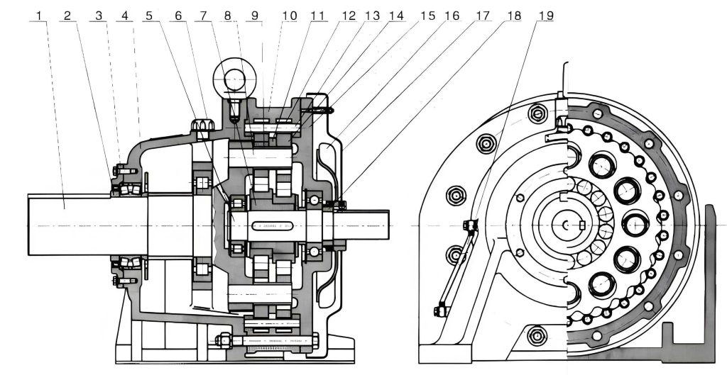
The efficiency and longevity of a cycloidal drive hinge on proper maintenance, which necessitates periodic disassembly. Common issues include wear on the eccentric sleeve and bearings, requiring careful removal to avoid damage. My method addresses these pitfalls through a tailored tool—a split ring—that protects components during extraction. Below, I detail the step-by-step procedure, but first, it is essential to visualize the internal arrangement of a cycloidal drive to appreciate the disassembly context.
The disassembly process begins with preparation and tool fabrication. For a given cycloidal drive, the bearing model on the eccentric sleeve must be identified. Based on this, I machine a split ring (or open washer) from durable material like mild steel. The ring’s dimensions are critical: its inner diameter \(D_2\) should slightly exceed the bearing cage’s outer diameter, while its outer diameter \(D_1\) is about 10 mm larger than the bearing ball’s outer diameter. The thickness \(t\) must be greater than the bearing inner race’s side thickness. Mathematically, if the bearing cage outer diameter is \(d_c\) and the ball set outer diameter is \(d_b\), then:
$$D_2 = d_c + \delta_1, \quad D_1 = d_b + 10 \text{ mm}, \quad t > t_{\text{race}}$$
where \(\delta_1\) is a small clearance (e.g., 0.5 mm). The ring is bisected into two semi-circular halves to facilitate insertion. This tool becomes a permanent asset for servicing that specific cycloidal drive model. The following table outlines typical dimensions for common bearing sizes in cycloidal drives:
| Bearing Model | Cage Outer Diameter (mm) | Ball Set Diameter (mm) | Recommended \(D_1\) (mm) | Recommended \(D_2\) (mm) |
|---|---|---|---|---|
| 6205 | 52 | 47 | 57 | 52.5 |
| 6308 | 90 | 85 | 95 | 90.5 |
| 6310 | 110 | 104 | 114 | 110.5 |
With the tool ready, the disassembly proceeds methodically. I first ensure the cycloidal drive is isolated from power and cleaned. The steps are as follows:
- Separation of Housing: Loosen all connecting bolts to detach the motor or input section from the needle housing. This exposes the internal components of the cycloidal drive.
- Removal of Pin Bushings: Extract all pin bushings or sleeves from the housing. These are often press-fitted and may require gentle tapping with a soft mallet.
- Disassembly of Shaft End: Remove the circlip (axial elastic ring) on the output shaft, followed by the bearing and any spacer rings. This step clears access to the cycloidal disc assembly.
- Application of Split Ring: Insert the two semi-circular halves through the pin holes of the upper cycloidal disc. Position them around the bearing cage on the eccentric sleeve, ensuring they sit beneath the balls and grip the cage exterior. Reassemble the needle housing temporarily, pressing the discs together to secure the ring. Then, attach a puller (e.g., a three-jaw puller) to the housing. By tightening the puller’s center screw, the entire assembly—including the eccentric sleeve and upper bearing—is extracted smoothly without direct force on the bearing races.
- Detaching Eccentric Sleeve or Bearing: If further disassembly is needed, place the cycloidal disc with the bearing on a vise. Position the split ring around the bearing cage, letting it rest on the vise jaws. Using a copper drift and hammer, strike the eccentric sleeve. The ring prevents the bearing balls from bearing load, transferring force to the sleeve instead. This protects the bearing from damage. The same technique applies to the opposite side bearing.
- Completion: Proceed with standard检修 procedures for other parts, such as inspecting the cycloidal disc for wear or replacing seals.
This method leverages mechanical advantage and precise tooling to safeguard the cycloidal drive’s integrity. To quantify the forces involved, consider the extraction process. When using the puller, the required extraction force \(F_e\) depends on the interference fit between the eccentric sleeve and bearing. Assuming a cylindrical fit, the pressure \(p\) at the interface is given by:
$$p = \frac{\delta}{d \left( \frac{1}{E_o} \left( \frac{d^2 + d_i^2}{d^2 – d_i^2} + \nu_o \right) + \frac{1}{E_i} \left( \frac{d_o^2 + d^2}{d_o^2 – d^2} – \nu_i \right) \right)}$$
where \(\delta\) is the interference, \(d\) is the nominal diameter, \(E_o\) and \(E_i\) are Young’s moduli of outer and inner parts, \(\nu_o\) and \(\nu_i\) are Poisson’s ratios, and \(d_i\) and \(d_o\) are inner and outer diameters. The extraction force is then \(F_e = \pi d L \mu p\), with \(L\) as the contact length and \(\mu\) the coefficient of friction. My split ring method reduces \(F_e\) by distributing load evenly, preventing stress concentration that could deform the bearing.
In practice, the cycloidal drive’s performance metrics, such as efficiency \(\eta\), can be affected by disassembly-induced damage. Efficiency is typically high, often exceeding 90%, and is modeled as:
$$\eta = 1 – \frac{P_{\text{loss}}}{P_{\text{in}}}$$
where \(P_{\text{loss}}\) includes friction losses from bearings and seals. Proper disassembly maintains these efficiencies by avoiding brinelling or misalignment. To illustrate common issues and solutions, here is a table comparing traditional vs. my method:
| Aspect | Traditional Disassembly | Proposed Method with Split Ring |
|---|---|---|
| Risk of Bearing Damage | High due to direct prying or hammering | Low, as ring shields bearing elements |
| Tooling Required | Generic pullers, hammers, often improvised | Custom split ring, standard puller |
| Time Efficiency | Lengthy, with trial and error | Rapid, repeatable for same cycloidal drive type |
| Component Preservation | Often results in scratched or deformed parts | Excellent, extends service life of cycloidal drive |
| Skill Level Needed | Moderate to high, prone to errors | Simplified, suitable for trained technicians |
Beyond disassembly, understanding the cycloidal drive’s dynamics enriches maintenance practices. The torque transmission involves complex contact mechanics between the cycloidal disc and pins. The normal force \(F_n\) at each pin can be approximated using Hertzian contact theory. For a pin of radius \(R_p\) and disc lobe radius \(R_d\), the contact pressure \(p_c\) is:
$$p_c = \sqrt{\frac{F_n E^*}{\pi R^*}}$$
where \(E^*\) is the equivalent Young’s modulus, and \(R^*\) is the reduced radius: \(1/R^* = 1/R_p + 1/R_d\). During disassembly, avoiding impacts that could alter these radii is crucial; hence, my method’s gentle extraction preserves the cycloidal drive’s kinematic accuracy.
Furthermore, the design of the split ring can be optimized using finite element analysis (FEA). Stress distribution in the ring under load should remain below the yield strength \(\sigma_y\) of the material. For a ring subjected to a radial force \(F_r\) from the bearing balls, the maximum stress \(\sigma_{\text{max}}\) in bending is approximated by:
$$\sigma_{\text{max}} = \frac{M c}{I}$$
where \(M\) is the bending moment, \(c\) is the distance from neutral axis, and \(I\) is the area moment of inertia. For a rectangular ring cross-section of width \(w\) and thickness \(t\), \(I = w t^3 / 12\). Ensuring \(\sigma_{\text{max}} < \sigma_y\) guarantees the ring’s durability for multiple uses on the same cycloidal drive.
In operational contexts, the cycloidal drive is subjected to varying loads, necessitating regular inspection cycles. I recommend disassembly every 5,000 to 10,000 hours, depending on the application’s severity. The split ring method not only expedites this but also reduces downtime—a critical factor in industrial settings. For instance, in conveyor systems or robotics where cycloidal drives are prevalent, minimizing maintenance windows enhances overall productivity.
To elaborate on tool fabrication, the machining tolerances are vital. The inner diameter \(D_2\) should have a tolerance of ISO IT7 or finer to ensure a snug fit without binding. Using a lathe or CNC, the ring can be produced quickly. Material selection is also key; I prefer carbon steel for its balance of strength and machinability. For corrosive environments, stainless steel variants may be used, though this increases cost. The table below provides guidelines for ring materials based on cycloidal drive operating conditions:
| Operating Environment | Recommended Ring Material | Yield Strength (MPa) | Notes |
|---|---|---|---|
| General Industrial | Mild Steel (AISI 1020) | 350 | Cost-effective, easy to machine |
| High-Load Applications | Alloy Steel (AISI 4140) | 655 | Heat-treated for durability |
| Corrosive or Cleanroom | Stainless Steel (AISI 304) | 215 | Resists rust, suitable for food/pharma cycloidal drives |
Another aspect is the reassembly of the cycloidal drive after servicing. Proper alignment of the eccentric sleeve is paramount to prevent vibration. I use dial indicators to ensure runout within 0.05 mm. The preload on bearings should be adjusted according to manufacturer specifications, often calculated via the bearing stiffness \(k_b\):
$$k_b = \frac{dF}{d\delta}$$
where \(F\) is the axial load and \(\delta\) is the deflection. Over-tightening can reduce the cycloidal drive’s efficiency, while under-tightening leads to play.
In terms of innovation, this disassembly method reflects a broader philosophy of preventive maintenance for cycloidal drives. By integrating custom tooling with empirical knowledge, I have streamlined processes that otherwise rely on brute force. The cycloidal drive, with its intricate geometry, deserves such meticulous care to uphold its performance advantages. Future advancements may include 3D-printed split rings for rapid prototyping, though metal remains preferred for longevity.
To conclude, the cycloidal drive is a masterpiece of mechanical design, and its maintenance should be equally refined. My disassembly technique, centered on a simple yet effective split ring, offers a reproducible, damage-free approach. By adhering to the steps outlined and leveraging the mathematical principles behind the cycloidal drive, technicians can ensure reliable operation across countless cycles. As industries evolve towards automation and precision, such methodologies will become standard practice, preserving the cycloidal drive’s role as a cornerstone of motion control systems.