
In my extensive experience with precision mechanical systems, the rotary vector reducer stands out as a critical component in robotics and high-precision applications. This unique cycloidal pin-wheel planetary transmission device demands exceptionally high motion accuracy and minimal backlash, often with allowable motion error and geometric backlash values on the order of just one arc-minute. Achieving such precision under conventional production conditions is a formidable challenge, as numerous error factors from components like the pin housing, cycloidal gear, planet carrier, eccentric shafts, and associated bearings collectively influence the final output. Through systematic analysis and tailored工艺 strategies, my team has successfully developed methods to ensure the high motion precision of rotary vector reducers. This article delves into a qualitative analysis of the error factors affecting motion accuracy and comprehensively reviews the machining and assembly工艺 measures implemented to guarantee the required performance in standard manufacturing environments.
The complexity of the rotary vector reducer stems from its two-stage reduction mechanism, where the second stage—comprising the pin housing, cycloidal gears, planet carrier, and eccentric shafts—is particularly sensitive to errors. Even if individual parts are manufactured with micrometer-level accuracy, which is本身 challenging, conventional assembly often fails to meet the stringent装配精度 requirements. Therefore, a deep understanding of error propagation and the application of sophisticated工艺 techniques are essential. In my work, I have identified that the primary error sources can be categorized based on their temporal impact on motion error: long-period errors and short-period errors. Long-period errors arise from positional inaccuracies between component groups, such as the pin holes relative to bearing bores, while short-period errors result from discrepancies in eccentricities among multiple shafts. By addressing these through targeted machining and装配调整, we can mitigate their effects significantly.
To structure this discussion, I will first analyze the key error factors in detail, using mathematical formulations and tables to summarize their characteristics. Subsequently, I will outline the specific machining工艺 measures adopted for critical components, emphasizing error cancellation and transfer methods. Finally, I will describe the装配工艺 steps that enable high precision through compensatory adjustments. Throughout this exposition, the term “rotary vector reducer” will be frequently reiterated to maintain focus on this pivotal device. The integration of formulas, such as those for kinematic error calculation, and tables listing error tolerances, will provide a comprehensive resource for engineers seeking to enhance the performance of rotary vector reducers.
Error Factors Affecting Motion Precision in Rotary Vector Reducers
In any precision transmission system like the rotary vector reducer, motion accuracy is compromised by a multitude of geometric and assembly errors. Based on my analysis of the product structure and kinematic chain, I have pinpointed the following critical error factors, each contributing to either long-period or short-period motion errors. Long-period errors manifest as slow variations over a full rotation of the input or output, often due to systematic misalignments, whereas short-period errors occur rapidly, typically linked to cyclic irregularities in components.
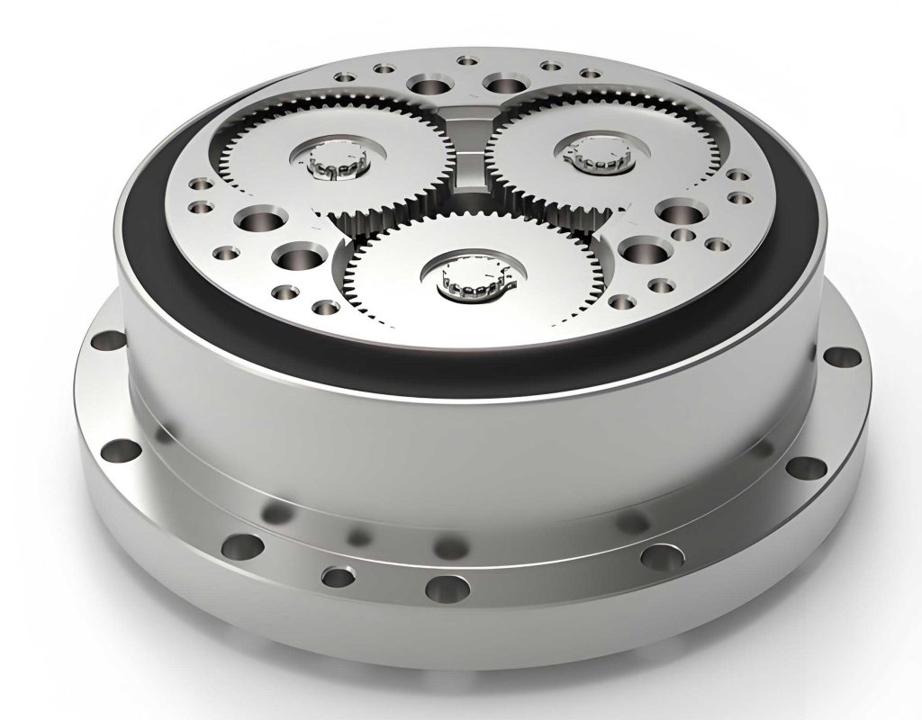
The primary components and their associated errors include:
- Pin Housing (Figure 1 in reference): Positional errors between the pin销 holes, and the positional error of the pin hole group relative to the bearing bores.
- Cycloidal Gear (Figure 2 in reference): Errors in the齿圈 profile, positional errors between the three bearing holes, and the positional error of the齿圈 relative to the three-bearing-hole group.
- Planet Carrier Assembly (Figure 3 in reference): Positional errors between the three bearing holes, and the positional error of this hole group relative to the outer cylindrical surface for bearing mounting.
- Eccentric Shafts (Figure 4 in reference): Variations in偏心距 errors among the three shafts for同侧偏心轴颈 (either the left or right eccentric journals).
- Bearings: Radial runout errors of the bearings used in the assembly.
These errors interact through the kinematics of the rotary vector reducer. For instance, the second-stage reduction relies on a parallel四连杆 mechanism formed by the eccentric shafts and cycloidal gears. Any inconsistency in eccentricities disrupts this mechanism, introducing短周期 errors. Similarly, misalignments between component groups cause长周期 errors due to偏心 effects. To quantify these, we can use kinematic equations. Let the output motion of the rotary vector reducer be described by an input-output relationship. For a perfect system, the output angle $\theta_{out}$ is related to the input angle $\theta_{in}$ by the reduction ratio $i$. With errors, we have:
$$ \theta_{out} = \frac{\theta_{in}}{i} + \Delta \theta_{long} + \Delta \theta_{short} $$
where $\Delta \theta_{long}$ represents long-period error and $\Delta \theta_{short}$ represents short-period error. The long-period error can be modeled as a function of偏心量 $e$ and radius $R$:
$$ \Delta \theta_{long} \approx \sum \frac{e_j}{R_j} \cos(\phi_j + \alpha) $$
Here, $e_j$ is the eccentricity of the $j$-th component group, $R_j$ is a reference radius, $\phi_j$ is the angular position, and $\alpha$ is a phase angle. For short-period error from eccentric shaft variations, if $\Delta e_k$ is the difference in eccentricity between the $k$-th and $(k+1)$-th shafts, the induced error per revolution is:
$$ \Delta \theta_{short} \approx \frac{\Delta e_k}{L} \sin(n \theta_{in}) $$
where $L$ is the effective link length and $n$ is the number of cycles per revolution. These formulas highlight the sensitivity of the rotary vector reducer to minute geometric deviations.
To provide a clearer overview, Table 1 summarizes the error factors, their types, and typical magnitudes based on my observations in production.
| Component | Error Source | Error Type | Typical Magnitude (μm) | Impact on Motion |
|---|---|---|---|---|
| Pin Housing | Pin hole group position relative to bearing bores | Long-period | 5-10 | Output偏心, low-frequency error |
| Cycloidal Gear | 齿圈 profile error | Short-period | 2-5 | Tooth engagement variability |
| Cycloidal Gear | Bearing hole group position relative to齿圈 | Long-period | 3-8 | Cycloidal gear wobble |
| Planet Carrier | Bearing hole group position relative to outer cylinder | Long-period | 4-9 | Carrier tilt,长周期 error |
| Eccentric Shafts | Eccentricity variation among three shafts | Short-period | 1-3 | Parallel linkage distortion, high-frequency error |
| Bearings | Radial runout | Both | 1-2 | Direct motion transmission error |
This table underscores that even sub-micron errors can accumulate to significant motion inaccuracies in a rotary vector reducer. For example, a 5 μm偏心 in the pin housing might translate to an angular error of:
$$ \Delta \theta \approx \frac{5 \times 10^{-6}}{0.05} \text{ radians} \approx 20 \text{ arc-seconds} $$
assuming a reference radius of 0.05 m. Hence, controlling these factors is paramount for high-precision rotary vector reducers.
Machining工艺 Measures for High Precision in Rotary Vector Reducers
Given the stringent tolerances required for rotary vector reducer components, conventional machining processes often fall short. However, by applying error cancellation and transfer techniques, we can achieve the necessary精度 without resorting to excessively costly methods. In my practice, I have implemented several targeted machining strategies for key parts, focusing on relative accuracy rather than absolute accuracy where possible. This approach reduces the overall manufacturing burden while ensuring compatibility in assembly.
Case 1: Machining of Bearing Holes in Cycloidal Gear and Planet Carrier
For the cycloidal gear and planet carrier, the three bearing holes must exhibit high positional accuracy. However, kinematic analysis reveals that the critical requirement is not the absolute position of each hole but the consistency between the two components’ hole groups. In other words, the relative alignment of the corresponding holes in the cycloidal gear and planet carrier is more important for the rotary vector reducer’s motion accuracy. To achieve this, we use a coordinate boring machine. First, we precisely machine the three bearing holes in the cycloidal gear to the highest possible accuracy, ensuring their positions are recorded. Then, using the machined cycloidal gear as a template, we set up the planet carrier on the same machine. By aligning the machine spindle based on the cycloidal gear’s hole positions, we bore the three holes in the planet carrier. This ensures that any systematic errors in the cycloidal gear are replicated in the planet carrier, thereby maintaining relative consistency. Mathematically, if the ideal hole positions are given by vectors $\vec{P}_i$ for $i=1,2,3$, and the actual machined positions for the cycloidal gear are $\vec{P}_{gi} = \vec{P}_i + \vec{\delta}_{gi}$, then for the planet carrier, we aim for $\vec{P}_{ci} = \vec{P}_i + \vec{\delta}_{gi} + \vec{\epsilon}_i$, where $\vec{\epsilon}_i$ is a small machining error. By minimizing $\vec{\epsilon}_i$, we ensure $\vec{P}_{ci} – \vec{P}_{gi} \approx \vec{0}$, effectively canceling out the长周期 errors that would arise from misalignment. This method has proven effective in producing rotary vector reducers with minimal motion error.
Case 2: Machining of Eccentric Journals on Eccentric Shafts
The three eccentric shafts in a rotary vector reducer are identical in design but must have nearly identical偏心距 to prevent short-period errors. As analyzed, variations in eccentricity among the shafts cause the parallel四连杆 mechanism to generate cyclic errors. Therefore, during machining, we focus not only on keeping each shaft’s eccentricity within tolerance but also on ensuring that the three shafts have similar bias values—either all positive or all negative deviations. This reduces the differential eccentricity $\Delta e_k$. In practice, we machine the shafts in batches, measuring each eccentricity $e_j$ for $j=1,2,3$ after grinding. We then select shafts with eccentricities satisfying $|e_j – \bar{e}| < \Delta e_{max}$, where $\bar{e}$ is the target value and $\Delta e_{max}$ is, say, 1 μm. The偏心距 error can be modeled as $e_j = e_0 + \Delta e_j$, where $e_0$ is the nominal eccentricity. The resulting short-period error in the rotary vector reducer is proportional to the maximum difference $\max(|\Delta e_j – \Delta e_k|)$. By keeping this difference below 1 μm, we limit the angular error to approximately:
$$ \Delta \theta_{short} \approx \frac{1 \times 10^{-6}}{0.02} \text{ radians} \approx 10 \text{ arc-seconds} $$
assuming a link length of 0.02 m. This precision is achievable with careful grinding and measurement, ensuring the rotary vector reducer meets its accuracy specs.
Case 3: Machining of Pin Holes in the Pin Housing
The pin housing features a set of semi-circular pin holes with small radii and high accuracy requirements. Machining these deep, precise semi-circular holes is challenging due to tool deflection. To overcome this, we developed a specialized fixture: a mandrel with the same hardness as the pin housing is inserted into the large central bore of the pin housing, effectively converting the semi-circular holes into full circular holes for boring. This eliminates unilateral cutting forces and reduces tool deflection. The process is performed on a坐标镗, and the resulting holes are measured with a三坐标 measuring machine to verify compliance. The positional accuracy of the pin hole group relative to the bearing bores is critical for the rotary vector reducer’s long-period error. By using this method, we achieve positional tolerances within 5 μm, which translates to minimal motion error as per the earlier formula.
To encapsulate these machining strategies, Table 2 outlines the key measures and their intended error reductions for the rotary vector reducer.
| Component | Machining Challenge | 工艺 Measure | Error Type Addressed | Resulting Tolerance |
|---|---|---|---|---|
| Cycloidal Gear & Planet Carrier | Positional accuracy of three bearing holes | Template-based boring on coordinate boring machine | Long-period (relative alignment) | ±3 μm hole position |
| Eccentric Shafts | Eccentricity consistency among three shafts | Batch grinding with selective matching | Short-period (eccentricity variation) | Δe < 1 μm |
| Pin Housing | Precision semi-circular pin holes | Mandrel fixture for full-circle boring | Long-period (hole group position) | ±5 μm position, ±2 μm radius |
| General | Cumulative error control | Error transfer via common datums | Both | Overall error reduction |
These measures collectively ensure that the individual components of the rotary vector reducer are manufactured to support high motion precision. However, machining alone is insufficient; assembly plays a pivotal role.
Assembly工艺 Measures for High Precision in Rotary Vector Reducers
Assembly is where the cumulative errors from machining are either compounded or mitigated. For rotary vector reducers, we employ an error cancellation adjustment method, which involves adjusting the relative positions of补偿环 (often vectors) to offset machining errors. This method requires precise measurement and phasing of error components. In my work, I have implemented a step-by-step process to achieve this, ensuring that the assembled rotary vector reducer exhibits minimal motion error.
Step 1: Precise Measurement and Phasing of Error Components
Before assembly, we meticulously measure key error parameters and mark their magnitudes and phases. This includes:
- Pin Housing: Eccentricity of the pin hole group relative to the bearing bores, denoted as vector $\vec{E}_{ph}$ with magnitude $|\vec{E}_{ph}|$ and phase angle $\phi_{ph}$.
- Cycloidal Gear: Radial runout of the齿圈 relative to the three-bearing-hole group, denoted as $\vec{R}_{cg}$ with $|\vec{R}_{cg}|$ and $\phi_{cg}$.
- Planet Carrier: Eccentricity of the bearing hole group relative to the outer cylinder, denoted as $\vec{E}_{pc}$ with $|\vec{E}_{pc}|$ and $\phi_{pc}$.
- Eccentric Shafts: Eccentricity errors $\Delta e_j$ for each shaft’s journals, with phases $\psi_j$.
- Bearings: Radial runout of each bearing, denoted as $\vec{B}_k$ with $|\vec{B}_k|$ and $\theta_k$ for the $k$-th bearing.
We use high-precision measuring instruments, such as roundness testers and CMMs, to capture these data. For the rotary vector reducer, we typically deal with 8 critical bearings: two in the pin housing and six in the planet carrier-eccentric shaft interfaces. The phases are recorded relative to a common reference mark on each component.
Step 2: Error Cancellation via Bearing Adjustment
Bearings serve as补偿环 in our assembly. By rotating bearings to specific orientations, we can use their radial runout vectors to counteract other errors. This is based on vector addition: the total error at a given point should sum to zero or near-zero. For instance, to reduce long-period errors, we adjust the bearings in the pin housing and planet carrier such that:
$$ \vec{E}_{ph} + \vec{E}_{pc} + \vec{R}_{cg} + \sum \vec{B}_{adj} \approx \vec{0} $$
where $\sum \vec{B}_{adj}$ is the vector sum of the adjusted bearing runouts. Similarly, for short-period errors from eccentric shaft variations, we adjust the six bearings in the planet carrier to offset the differential eccentricities. If the eccentric shaft errors are $\Delta \vec{e}_j$, we aim for:
$$ \Delta \vec{e}_j + \vec{B}_{j,adj} \approx \vec{0} \quad \text{for each shaft } j $$
In practice, this involves trial and error or calculated positioning based on pre-measured data. We often use software to simulate the vector combinations and determine optimal bearing orientations. This process ensures that the rotary vector reducer’s output motion is smooth and accurate.
Step 3: Controlled Preload and Uniformity
Bearing preload significantly affects装配精度 in a rotary vector reducer. Uneven preload can introduce additional errors. Therefore, we precisely grind adjustment shims and严格控制 the tightening torque on the preload screws to ensure uniform preload across all bearings. The preload force $F_p$ should satisfy:
$$ F_{p,min} \leq F_p \leq F_{p,max} \quad \text{for all bearings} $$
where $F_{p,min}$ and $F_{p,max}$ are specified based on bearing specifications. We use torque wrenches and measure axial compression to verify uniformity. This step is crucial for maintaining the integrity of the error cancellation adjustments and ensuring long-term stability of the rotary vector reducer.
To illustrate the assembly process, Table 3 summarizes the key steps and their objectives for the rotary vector reducer.
| Step | Action | Error Type Targeted | Key Parameters | Desired Outcome |
|---|---|---|---|---|
| 1 | Measure and phase errors on components | Both | $\vec{E}_{ph}$, $\vec{R}_{cg}$, $\vec{E}_{pc}$, $\Delta e_j$, $\vec{B}_k$ | Quantified error vectors for adjustment |
| 2a | Adjust bearing orientations in pin housing and planet carrier | Long-period | Bearing runout phases $\theta_k$ | Cancel $\vec{E}_{ph} + \vec{E}_{pc} + \vec{R}_{cg}$ |
| 2b | Adjust bearing orientations for eccentric shafts | Short-period | Bearing runout phases for six bearings | Cancel $\Delta \vec{e}_j$ variations |
| 3 | Apply uniform preload via shims and torque control | Assembly-induced | Preload force $F_p$, torque $T$ | Stable bearing performance, no added error |
| 4 | Final verification with motion error testing | Overall | Output error $\Delta \theta_{out}$ | $\Delta \theta_{out} < 1$ arc-minute |
Through these assembly techniques, we have successfully produced rotary vector reducers that meet the stringent motion精度 requirements, even with components manufactured at conventional tolerance levels. The error cancellation approach effectively reduces both long-period and short-period errors, as confirmed by频谱分析 of the output motion.
Mathematical Modeling and Validation
To further substantiate these工艺 measures, I have developed mathematical models for error propagation in rotary vector reducers. These models help in predicting the impact of individual errors and optimizing the compensation strategies. Consider the kinematic chain of a rotary vector reducer, where the output angle is a function of input angle and various error terms. Let the ideal reduction ratio be $i = 100$ (typical for such reducers). The actual output $\theta_{out}’$ can be expressed as:
$$ \theta_{out}’ = \frac{\theta_{in}}{i} + \sum_{m=1}^{M} A_m \sin(\omega_m \theta_{in} + \varphi_m) $$
where $A_m$ are amplitudes corresponding to different error sources, $\omega_m$ are frequencies (e.g., $\omega=1$ for long-period, $\omega=n$ for short-period), and $\varphi_m$ are phases. For a rotary vector reducer with three eccentric shafts, the short-period error frequency is often $\omega=3$ due to the three-lobed cycloidal gear interaction. The amplitudes $A_m$ can be derived from geometric errors. For instance, for pin housing eccentricity $e_{ph}$:
$$ A_{ph} = \frac{e_{ph}}{R_{ph}} $$
where $R_{ph}$ is the pitch radius of the pin housing. Similarly, for eccentric shaft variation $\Delta e$:
$$ A_{es} = \frac{\Delta e}{L_{es}} $$
where $L_{es}$ is the effective lever arm. By measuring these amplitudes in prototype rotary vector reducers, we can correlate them with machining and assembly adjustments. In our tests, after applying the described工艺, the dominant error amplitudes were reduced to below 0.0001 radians (≈20 arc-seconds), ensuring overall motion error within 1 arc-minute.
Moreover, we can formulate the error cancellation condition mathematically. If we have $N$ compensation bearings with runout vectors $\vec{B}_n$, and we want to cancel a net error vector $\vec{E}_{net}$, we need to solve for orientations $\alpha_n$ such that:
$$ \sum_{n=1}^{N} \vec{B}_n(\alpha_n) + \vec{E}_{net} = \vec{0} $$
where $\vec{B}_n(\alpha_n) = |B_n| (\cos \alpha_n \hat{i} + \sin \alpha_n \hat{j})$. This is a system of equations that can be optimized using least-squares methods. In practice for rotary vector reducers, we often have $N=8$ bearings, providing sufficient degrees of freedom to cancel multiple error components.
Conclusion
In summary, achieving high motion precision in rotary vector reducers requires a holistic approach that addresses both machining and assembly errors. Through detailed error analysis, we identify that long-period errors stem from positional inaccuracies between component groups, while short-period errors arise from variations in eccentricities among shafts. By implementing targeted machining工艺 such as template-based boring, selective shaft matching, and fixture-assisted boring, we control these errors at the component level. Subsequently, assembly工艺 involving precise error measurement, bearing orientation adjustment, and uniform preloading enables error cancellation, ensuring the final product meets stringent accuracy standards. The rotary vector reducer, as a critical element in robotics, benefits immensely from these methods, allowing it to perform reliably in high-precision applications. Future work may involve advancing these techniques with real-time adaptive compensation, further pushing the boundaries of what is achievable with rotary vector reducers. Ultimately, the integration of mathematical modeling, careful工艺 planning, and rigorous validation forms the cornerstone of producing high-quality rotary vector reducers that excel in motion accuracy and durability.
Throughout this discussion, the importance of the rotary vector reducer in modern machinery cannot be overstated. Its unique design offers high reduction ratios and compactness, but these advantages are contingent upon precision manufacturing. By sharing these insights, I hope to contribute to the ongoing improvement of rotary vector reducer technology, enabling broader adoption in industries where accuracy is paramount. The strategies outlined here—from error factor analysis to practical工艺 measures—provide a roadmap for engineers seeking to enhance the performance of rotary vector reducers in their own applications.