
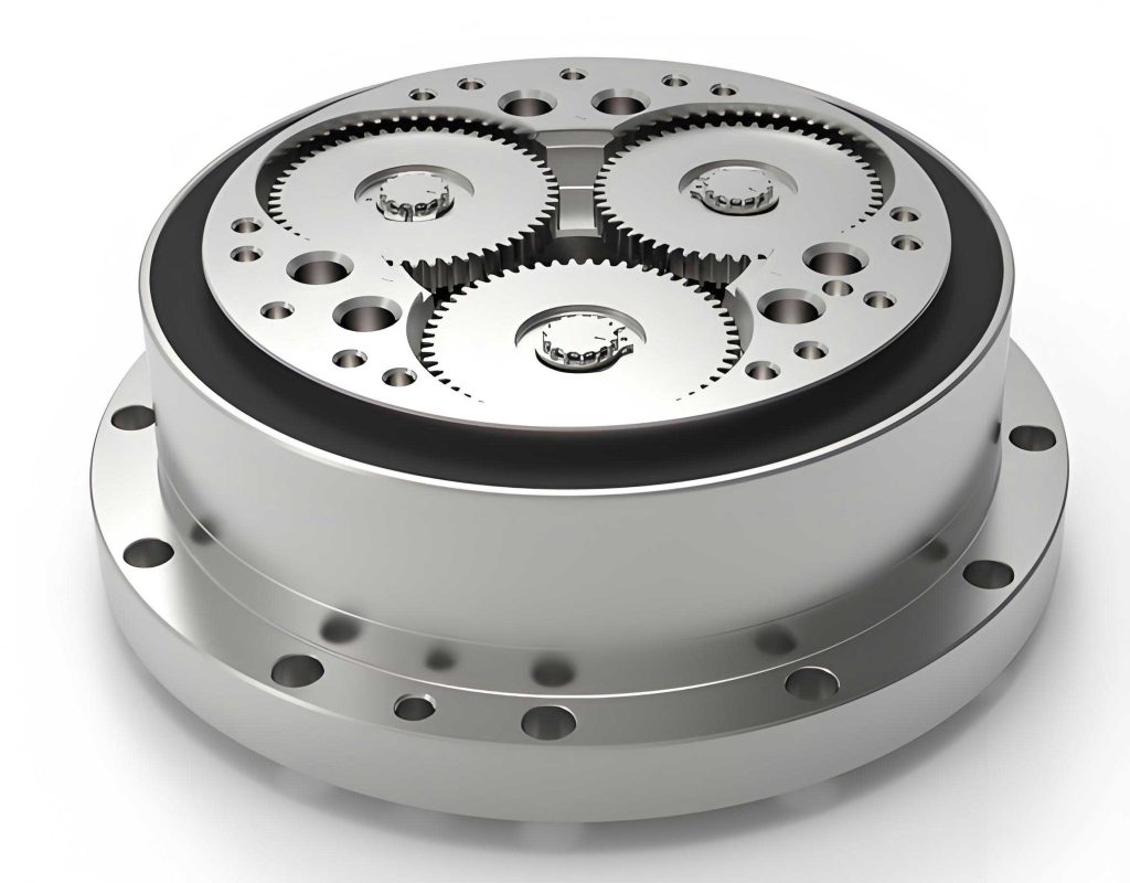
In this study, I present a comprehensive approach to the dynamic modeling of rotary vector reducers, focusing on the stiffness characteristics and structural parameter effects. Rotary vector reducers, often abbreviated as RV reducers, are advanced transmission systems derived from cycloidal drive mechanisms. They are renowned for their high reduction ratios, compact size, efficiency, and load-bearing capacity, making them ideal for precision applications such as robotics and industrial automation. However, the dynamic behavior of rotary vector reducers remains underexplored, with limited models available for predicting system stiffness and performance. This work aims to bridge that gap by developing a torsional dynamic model and analyzing key parameters that influence the stiffness and dynamics of rotary vector reducers.
The core of a rotary vector reducer consists of two primary stages: a cycloid-needle gear pair and an involute gear pair. The cycloid-needle transmission provides the main speed reduction, while the involute gears serve as the input stage. Understanding the mesh stiffness of these components is crucial for accurate dynamic modeling. I begin by deriving the mesh stiffness models based on Hertzian contact theory for the cycloid-needle pair and the Ishikawa formula for the involute gear pair. These models account for elastic deformations and contact mechanics, enabling a detailed analysis of the stiffness variations during operation.
To model the cycloid-needle pair, I consider the contact between the cycloid disc and the needle teeth as a line contact that deforms into a small elliptical area under load. According to Hertz theory, the contact deformation can be described for elastic materials. Assuming identical materials for the cycloid disc and needle teeth with Poisson’s ratio $\mu$ and elastic modulus $E$, the half-length $L$ of the contact zone under force $F_i$ at the $i$-th contact point is given by:
$$L = \sqrt{\frac{8 F_i \rho_i (1 – \mu^2)}{\pi b E}}$$
where $\rho_i$ is the radius of curvature at the contact point on the cycloid disc, $b$ is the width of the contact area, and other parameters are as defined in the derivation. From this, the radial compression deformation $t_z$ for a needle tooth and $t_c$ for a cycloid tooth are derived, leading to individual stiffness expressions. For a needle tooth, the stiffness $C_{zi}$ is:
$$C_{zi} = \frac{\pi b E R_z S^{3/2}}{4(1 – \mu^2) (R_z S^{3/2} + r_z T)}$$
and for a cycloid tooth, the stiffness $C_{bi}$ is:
$$C_{bi} = \frac{\pi b E R_z S^{3/2}}{4(1 – \mu^2) r_z T}$$
where $R_z$ is the needle gear radius, $r_z$ is the needle tooth radius, $K_1$ is the shortening coefficient, $\theta_b$ is the rotation angle, $z_b$ is the number of needle teeth, and $S$ and $T$ are geometric parameters defined as $S = 1 + K_1^2 – 2K_1 \cos \theta_b$ and $T = K_1(1 + z_b) \cos \theta_b – (1 + z_b K_1^2)$. The mesh stiffness for a single tooth pair $C_{si}$ is then obtained by combining these in series:
$$C_{si} = \frac{C_{bi} C_{zi}}{C_{bi} + C_{zi}} = \frac{\pi b E R_z S^{3/2}}{4(1 – \mu^2) (R_z S^{3/2} + 2 r_z T)}$$
For the overall cycloid-needle transmission, the equivalent torsional stiffness $C_{bz}$ is calculated by summing the contributions from all engaged tooth pairs, adjusted for factors like manufacturing errors and assembly inaccuracies using a coefficient $\lambda$ (typically 0.6 to 0.7). The expression is:
$$C_{bz} = \lambda \sum_{i=1}^{z_b/2} C_{si} L_i’^2$$
where $L_i’$ is the force arm at the $i$-th contact point. This stiffness varies periodically with the input speed and gear geometry. For instance, the variation frequency $f$ is:
$$f = \frac{n_2 z_b}{60(z_b – z_g)}$$
where $n_2$ is the speed of the double crankshaft and $z_g$ is the number of teeth on the cycloid disc. In practical terms, to avoid resonance, it is advisable to increase the first-stage transmission ratio and reduce the second-stage ratio in a rotary vector reducer, thereby lowering the stiffness variation frequency relative to the system’s natural frequencies.
For the involute gear pair, I employ the Ishikawa formula to model the mesh stiffness. The gear tooth is approximated as a combination of trapezoidal and rectangular sections, allowing the derivation of stiffness components such as bending, shear, and Hertzian contact. The single-tooth mesh stiffness $C_s’$ is given by:
$$C_s’ = \frac{1}{\frac{1}{C_{Br1}} + \frac{1}{C_{Bt1}} + \frac{1}{C_{S1}} + \frac{1}{C_{G1}} + \frac{1}{C_{Br2}} + \frac{1}{C_{Bt2}} + \frac{1}{C_{S2}} + \frac{1}{C_{G2}} + \frac{1}{C_{PV}}}$$
where $C_{Br}$, $C_{Bt}$, $C_{S}$, $C_{G}$, and $C_{PV}$ represent stiffness due to bending, tilting, shear, gear body deformation, and contact, respectively, with subscripts 1 and 2 denoting the two gears. According to ISO 6336-1996, this can be simplified using the pitch point stiffness, and the total mesh stiffness $C_d$ for the gear pair is approximated as:
$$C_d = C_s’ (0.75 \varepsilon_a + 0.25)$$
where $\varepsilon_a$ is the contact ratio. This simplification facilitates engineering applications without significant loss of accuracy.
Integrating these stiffness models, I develop a torsional dynamic model for the rotary vector reducer. The system is represented as a 5-degree-of-freedom model, incorporating the input gear, planetary gears, double crankshaft, cycloid disc, and output needle gear, with an inertial disk simulating the workload. The stiffness matrix $C_{5 \times 5}$ for this system is constructed based on the derived stiffness values. The equation of motion is:
$$J_{5 \times 5} \ddot{\theta}_{5 \times 1} + D_{5 \times 5} \dot{\theta}_{5 \times 1} + C_{5 \times 5} \theta_{5 \times 1} = \tau_{5 \times 1}$$
where $J$ is the inertia matrix, $D$ is the damping matrix, $\theta$ is the angular displacement vector, and $\tau$ is the torque vector. The natural frequencies of the system are computed from this model, highlighting the dominant role of the double crankshaft’s torsional stiffness in determining the first natural frequency.
To analyze the impact of structural parameters on the rotary vector reducer, I focus on the cycloid-needle pair. Key parameters include the number of needle teeth $z_b$, the needle gear radius $R_z$, and the needle tooth radius $r_z$. The effects of these parameters on mesh forces and stiffness are summarized in the table below, derived from simulations with a sample rotary vector reducer model (e.g., RV-6A II).
| Parameter | Effect on Mesh Force | Effect on Mesh Stiffness | Recommendations |
|---|---|---|---|
| Number of needle teeth ($z_b$) | Decreases as $z_b$ increases, due to load distribution across more teeth. The reduction rate slows at higher $z_b$. | Increases overall equivalent stiffness, as more teeth engage. Single-tooth stiffness peaks rise with $z_b$. | Increase $z_b$ up to ~30 for significant force reduction; beyond that, benefits diminish. |
| Needle gear radius ($R_z$) | Decreases force at all contact points, especially at high-force points, due to increased force arms. | Decreases overall stiffness for most contact points (where curvature is negative), but increases where curvature is positive. | Use moderate $R_z$ to balance force reduction and stiffness; avoid excessive sizes. |
| Needle tooth radius ($r_z$) | No direct effect on mesh forces. | Increases stiffness for negative curvature points and decreases for positive curvature points, with net increase in overall stiffness. | Increase $r_z$ to enhance rigidity, but avoid “undercutting” issues in design. |
The mathematical relationships for these effects can be expressed through the stiffness formulas. For example, the sensitivity of stiffness to $z_b$ is captured in the $S$ and $T$ terms, where increasing $z_b$ alters $\theta_b$ and thus $S$ and $T$. Similarly, for $R_z$, the stiffness $C_{si}$ varies inversely with $R_z$ in the denominator terms, while for $r_z$, the dependence is linear in the numerator and denominator. These insights are crucial for optimizing the design of rotary vector reducers to achieve desired performance metrics such as load capacity, rigidity, and dynamic response.
To validate the dynamic model, I conducted experimental tests on a prototype rotary vector reducer, specifically an RV-6A II model. The setup involved measuring the frequency response under controlled loads, with results indicating a first natural frequency of approximately 128 Hz and a static torsional stiffness in the range of 75–85 N·m/rad. The dynamic stiffness was measured at about 4.83 N·m/rad. These values align closely with the predictions from the model, confirming its accuracy and practicality for engineering applications. The tests also underscore the importance of the double crankshaft’s stiffness as the primary determinant of the system’s low-frequency dynamics, reinforcing the need for careful design of this component in rotary vector reducers.
In conclusion, this study provides a robust framework for dynamic modeling of rotary vector reducers, emphasizing stiffness analysis and parameter optimization. The key findings are: first, the mesh stiffness of the cycloid-needle pair varies periodically, and resonance can be mitigated by adjusting transmission ratios; second, the double crankshaft’s torsional stiffness dominates the first natural frequency, highlighting its critical role in dynamic performance; third, structural parameters like $z_b$, $R_z$, and $r_z$ significantly influence forces and stiffness, with trade-offs that designers must consider; and fourth, the model is experimentally validated, proving its utility for predicting system behavior. Future work could extend this approach to include damping effects, nonlinearities, and advanced materials, further enhancing the reliability and efficiency of rotary vector reducers in high-precision applications.
The development of such models is essential for advancing rotary vector reducer technology, enabling better performance prediction and design optimization. As demand for compact, high-torque reducers grows in fields like robotics, the insights from this study can guide engineers in creating more efficient and durable systems. By continuously refining these models, we can push the boundaries of what rotary vector reducers can achieve, contributing to innovation in mechanical transmission systems worldwide.