
In my extensive research on high-precision transmission systems for industrial robotics, I have focused on the critical role of the rotary vector reducer, a compact and efficient减速装置 that serves as the joint mechanism in robots. The performance of these reducers directly impacts the positioning accuracy, load capacity, and longevity of robotic systems. At the heart of the rotary vector reducer lies the cycloidal-pinwheel transmission, which operates at the low-speed end and is responsible for the final output motion. Therefore, controlling the transmission accuracy of this cycloidal-pinwheel pair is paramount to the overall precision of the rotary vector reducer. This article, based on my comprehensive review and analysis, delves into the current research landscape, key technological issues, and future directions in this field, emphasizing the need for advanced design, manufacturing, and dynamic analysis to enhance the performance of rotary vector reducers.
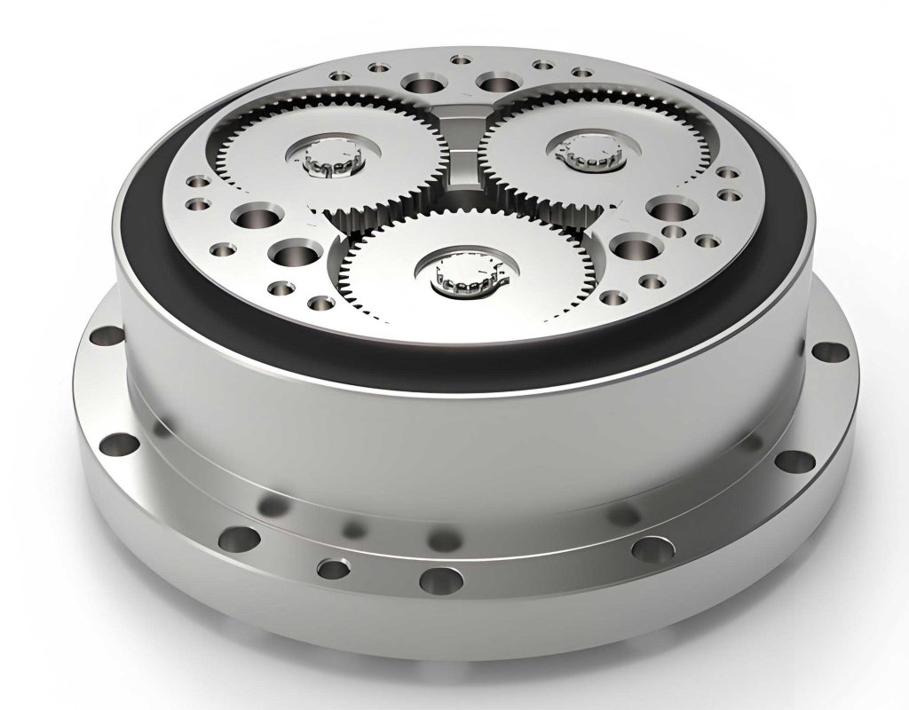
The rotary vector reducer combines a planetary gear mechanism with a cycloidal-pinwheel planetary transmission, offering advantages such as high reduction ratios, compact structure, excellent rigidity, and substantial load-bearing capacity. Its efficiency stems from the high stiffness of components and the ability to achieve multiple tooth contacts simultaneously. However, the cycloidal gear’s complex tooth profile necessitates precise modification, known as “修形” or modification, to accommodate manufacturing tolerances, ensure proper lubrication, and prevent jamming. Without modification, the theoretical perfect meshing of standard cycloidal profiles is impractical due to inevitable errors. My investigation reveals that modification techniques and accuracy control are central to optimizing the rotary vector reducer’s performance.
To structure my findings, I will first overview the current state of cycloidal gear modification technologies, then examine precision control strategies and dynamic studies related to the rotary vector reducer system. Finally, I will discuss emerging trends and unresolved technical challenges. Throughout, I will incorporate tables and mathematical formulations to summarize key concepts, ensuring a detailed exposition that meets the required depth.
Current Research Status on Cycloidal Gears
Modification Techniques for Cycloidal Gears
In my analysis, modification of cycloidal gears is essential to introduce necessary backlash, compensate for errors, and improve load distribution. The primary modification methods involve combinations of profile shifting (移距修形), equidistant modification (等距修形), and rotational correction (转角修形). Researchers have explored various optimization approaches to determine the best modification amounts for achieving multi-tooth contact and minimizing transmission error in rotary vector reducers.
For instance, a common approach is the combined positive equidistant and negative profile shifting modification, which approximates the conjugate profile in the working region. This method enhances load capacity by increasing the number of teeth in contact. Another optimized combination for high-precision, low-backlash applications in rotary vector reducers is negative equidistant with negative profile shifting. The mathematical model for such optimization can be expressed as minimizing the transmission error function subject to constraints on backlash and contact stress.
Let the theoretical cycloidal profile be defined by the parametric equations derived from the generating circle rolling around the base circle. For a standard cycloid, the coordinates $(x, y)$ of a point on the tooth profile are given by:
$$ x = R_c \cdot (\theta – \sin\theta) – r_p \cdot \sin(\phi) $$
$$ y = R_c \cdot (1 – \cos\theta) – r_p \cdot \cos(\phi) $$
where $R_c$ is the radius of the generating circle, $r_p$ is the pin radius, $\theta$ is the rolling angle, and $\phi$ is related to $\theta$ through the gear ratio. When modification is applied, these equations are adjusted. For equidistant modification $\Delta r_p$, the pin radius is effectively changed. For profile shifting $\Delta R_c$, the generating circle radius is altered. Rotational correction $\Delta \theta$ adjusts the phase. The modified profile becomes:
$$ x’ = (R_c + \Delta R_c) \cdot (\theta + \Delta \theta – \sin(\theta + \Delta \theta)) – (r_p + \Delta r_p) \cdot \sin(\phi’) $$
$$ y’ = (R_c + \Delta R_c) \cdot (1 – \cos(\theta + \Delta \theta)) – (r_p + \Delta r_p) \cdot \cos(\phi’) $$
where $\phi’$ is updated accordingly. The optimal modification amounts $\Delta R_c$, $\Delta r_p$, and $\Delta \theta$ are determined through numerical optimization to minimize the maximum contact stress or transmission error over the mesh cycle.
I have summarized different modification strategies and their impacts in the table below:
| Modification Method | Description | Advantages | Challenges |
|---|---|---|---|
| Positive Equidistant + Negative Profile Shifting | Increases pin radius and decreases generating circle radius. | Improves load distribution, multi-tooth contact. | May increase backlash if not optimized. |
| Negative Equidistant + Negative Profile Shifting | Decreases both pin and generating circle radii. | Reduces backlash, suitable for high-precision rotary vector reducers. | Risk of interference if over-modified. |
| Rotational Correction | Adjusts the phase angle of the cycloid. | Fine-tunes meshing timing, reduces vibration. | Complex to implement in manufacturing. |
| Combined Segmented Modification | Applies different corrections to working and non-working regions. | Optimizes stress and clearance, enhances durability. | Requires precise control and measurement. |
Moreover, the concept of “反弓齿廓” or reverse-arc tooth profile has been proposed, where the profile is optimized to reduce maximum contact force. This involves solving an optimization problem where the objective function is the peak contact stress, and variables are the modification parameters. The use of Tooth Contact Analysis (TCA) and Loaded Tooth Contact Analysis (LTCA) is crucial here. For example, the contact condition between the cycloidal gear and pin can be modeled as:
$$ \delta_i = \min \left( \sqrt{(x_i’ – X_p)^2 + (y_i’ – Y_p)^2} – r_p \right) $$
where $\delta_i$ is the clearance for tooth $i$, $(X_p, Y_p)$ is the pin center position, and minimization is over all teeth. The goal is to ensure $\delta_i$ is within a small tolerance for multiple teeth simultaneously.
In my view, while these modification techniques are well-studied for gear grinding via generating methods, there is a gap in research for modification tailored to form grinding processes, which are becoming more prevalent for high-efficiency, high-precision manufacturing of rotary vector reducer components.
Precision Control in Cycloidal-Pinwheel Transmission
Precision control encompasses the management of manufacturing errors, assembly tolerances, and the resulting transmission accuracy. The rotary vector reducer’s performance is highly sensitive to deviations in cycloidal gear geometry, pin placement, and bearing clearances. My review indicates that transmission error and backlash are key metrics. Transmission error $\Delta \theta_{out}$ can be defined as the difference between the actual output rotation and the ideal rotation for a given input, often influenced by tooth profile errors, pitch deviations, and mounting inaccuracies.
Researchers have developed analytical models to quantify these errors. For instance, the equivalent model approach represents the cycloidal-pinwheel transmission as a simplified kinematic chain to compute回转传动误差. The total transmission error $\Delta \theta_{total}$ can be expressed as a superposition of errors from various sources:
$$ \Delta \theta_{total} = \sum_{j} \frac{\partial \theta_{out}}{\partial e_j} \cdot \Delta e_j $$
where $e_j$ represents error sources such as pin position error $\Delta r_{p,j}$, cycloid profile error $\Delta f(\theta)$, and bearing radial play $\delta_b$. The sensitivity coefficients $\partial \theta_{out}/\partial e_j$ are derived from the mechanism’s geometry.
For a rotary vector reducer with $N_p$ pins and a cycloid gear with $N_c$ teeth, the ideal reduction ratio $i$ is $N_p / (N_p – N_c)$. Due to errors, the actual ratio varies. The instantaneous transmission error can be modeled considering the contact deformations and clearances. Let $K_{contact}$ be the contact stiffness per tooth pair, and $F_i$ the load on tooth $i$. The deformation $\delta_i$ contributes to angular error:
$$ \Delta \theta_{error} = \frac{1}{R_{output}} \sum_{i=1}^{N_{contact}} \delta_i \cdot \cos(\psi_i) $$
where $R_{output}$ is the output radius, $\psi_i$ is the pressure angle, and $N_{contact}$ is the number of teeth in contact. This dynamic error is critical for the rotary vector reducer under load.
I have compiled common error sources and their effects in the table below:
| Error Source | Description | Impact on Rotary Vector Reducer | Typical Magnitude |
|---|---|---|---|
| Cycloid Profile Error | Deviation from ideal tooth form due to grinding inaccuracies. | Increased transmission error, vibration, noise. | ±5–10 μm |
| Pin Position Error | Radial or angular deviation of pins in the pinwheel. | Uneven load distribution, reduced accuracy. | ±3–8 μm |
| Pitch Cumulative Error | Accumulated error in tooth spacing over the cycloid gear. | Low-frequency oscillation in output, reduced positional precision. | ±10–20 arcsec |
| Assembly Misalignment | Misalignment between cycloid gear, pins, and bearings. | Increased backlash, wear, and dynamic loads. | 10–30 μm |
| Bearing Clearance | Radial play in the crankshaft bearings. | Hysteresis, non-linear stiffness, impact on dynamic response. | 5–15 μm |
Measurement techniques are vital for precision control. While coordinate measuring machines (CMMs) and tool microscopes are used, specialized gear measuring centers with software for cycloidal gear evaluation are needed. Error compensation strategies involve iterative correction in manufacturing based on metrology data. For example, if profile error $\Delta f(\theta)$ is measured, the grinding path can be adjusted using a correction function $C(\theta)$ so that the manufactured profile $f_{mfg}(\theta) = f_{ideal}(\theta) + C(\theta)$, aiming to minimize $\Delta f(\theta)$. This closed-loop approach is essential for high-precision rotary vector reducers.
My assessment is that current methods still struggle with dynamic error reduction under operational conditions. The static transmission error might be small, but dynamic effects due to time-varying mesh stiffness and inertial forces can degrade performance. Thus, integrating error analysis with dynamic modeling is crucial.
Dynamics Research on Rotary Vector Reducer Systems
The dynamic behavior of the rotary vector reducer influences its vibration, noise, and longevity. In my research, I have explored how dynamic models can predict natural frequencies, mode shapes, and response to loads. The system includes multiple components: input shaft, planetary gears, crankshafts, cycloidal gears, pins, and output mechanism. A lumped-parameter model can be developed using Newton-Euler equations or Lagrangian methods.
Consider a simplified torsional model for the rotary vector reducer. Let $J_in$ be the input inertia, $K_{shaft}$ the shaft stiffness, $J_{cycloid}$ the cycloid gear inertia, and $K_{mesh}$ the time-varying mesh stiffness between cycloid teeth and pins. The equation of motion for the output rotation $\theta_{out}$ can be written as:
$$ J_{eq} \ddot{\theta}_{out} + C_{eq} \dot{\theta}_{out} + K_{mesh}(t) \cdot \theta_{out} = T_{in} \cdot i – T_{load} $$
where $J_{eq}$ is the equivalent inertia reflected to the output, $C_{eq}$ is damping, $T_{in}$ is input torque, $i$ is reduction ratio, and $T_{load}$ is external load. The mesh stiffness $K_{mesh}(t)$ is periodic with the cycloid rotation and can be expanded as:
$$ K_{mesh}(t) = K_0 + \sum_{n=1}^{\infty} K_n \cos(n \omega_m t + \phi_n) $$
where $\omega_m$ is the mesh frequency. This variation excites vibrations, affecting the accuracy of the rotary vector reducer.
Finite element analysis (FEA) and multi-body dynamics (MBD) simulations are widely used. For instance, in ADAMS or similar software, a virtual prototype of the rotary vector reducer can be built to analyze contact forces, accelerations, and stresses. Key dynamic indicators include:
- Natural frequencies: To avoid resonance with operational speeds.
- Modal shapes: Identifying bending or torsional modes of components like crankshafts.
- Dynamic transmission error: The fluctuating component of output error due to inertial and stiffness effects.
I have derived a formula for dynamic transmission error $\Delta \theta_{dyn}$ considering a single degree-of-freedom model:
$$ \Delta \theta_{dyn} = \frac{F_{exc}}{K_{mesh}(t)} \cdot \sin(\omega t) $$
where $F_{exc}$ is the excitation force amplitude from mass unbalance or manufacturing errors. This error contributes to the overall inaccuracy of the rotary vector reducer.
Studies show that improving the rigidity of the cycloid gear and optimizing bearing preload can suppress vibrations. For example, the contact force $F_c$ between a cycloid tooth and pin under dynamic conditions can be estimated as:
$$ F_c = K_{contact} \cdot \delta + C_{contact} \cdot \dot{\delta} $$
where $\delta$ is the deformation and $C_{contact}$ is damping. Reducing $\delta$ through design enhancements lowers dynamic loads.
Moreover, virtual prototyping allows for parameter studies. I have created a table summarizing dynamic factors and mitigation strategies for rotary vector reducers:
| Dynamic Factor | Description | Effect on System | Mitigation Approach |
|---|---|---|---|
| Time-Varying Mesh Stiffness | Cyclic change as teeth engage/disengage. | Vibration excitation, noise. | Optimize tooth profile for constant stiffness; use damping materials. |
| Inertial Imbalances | Unbalanced masses in rotating parts like crankshafts. | Increased bearing loads, resonance. | Precision balancing; lightweight designs. |
| Bearing Clearance Nonlinearity | Backlash in bearings causing impact. | Hysteresis, reduced positional accuracy. | Preload bearings; use zero-backlash bearings. |
| Structural Flexibility | Bending of components under load. | Misalignment, added transmission error. | Increase stiffness via material selection; ribbed designs. |
| Thermal Effects | Expansion/contraction from temperature changes. | Altered clearances, preload loss. | Thermal compensation in design; cooling systems. |
My dynamic analyses indicate that while current rotary vector reducers perform well under static conditions, their dynamic accuracy—especially under varying loads—needs improvement. Integrating control algorithms with real-time error compensation could be a future direction.
Development Trends and Key Technological Problems
Based on my research, the evolution of cycloidal-pinwheel transmission for rotary vector reducers is moving toward higher precision, durability, and intelligent manufacturing. The trends can be categorized into design theory, manufacturing technology, dynamics, and manufacturing equipment.
Design Theory Advancements
Future work should focus on modification techniques for form grinding processes. Unlike generating grinding, form grinding uses a shaped wheel to directly profile the tooth, offering higher efficiency and flexibility for complex modifications. The mathematical model for form grinding must account for wheel geometry and path optimization. Let the wheel profile be defined by a function $W(u)$ in wheel coordinates, and the desired cycloid profile be $C(\theta)$ after modification. The grinding path $P(t)$ must ensure that the envelope of $W(u)$ matches $C(\theta)$. This involves solving for $P(t)$ such that:
$$ \min_{P(t)} \int |E(\theta)|^2 d\theta $$
where $E(\theta)$ is the error between the ground profile and $C(\theta)$. Topological modification, where the modification varies along the tooth face width, can further optimize contact patterns. This requires advanced TCA and LTCA simulations to predict performance under load for the rotary vector reducer.
Moreover, the integration of artificial intelligence for optimization is promising. Neural networks can be trained to predict transmission error based on modification parameters, speeding up the design process for rotary vector reducers.
Manufacturing Technology and Precision Control
To achieve ultra-high precision, manufacturing errors must be minimized. This involves developing high-accuracy grinding machines, in-process measurement, and error compensation. The relationship between machine tool errors and gear errors can be modeled. For example, in form grinding, if the wheel has a radius error $\Delta R_w$, it induces a profile error $\Delta f$ approximately:
$$ \Delta f \approx \frac{\partial f}{\partial R_w} \cdot \Delta R_w $$
Calibration and closed-loop control can reduce such errors. Additionally, the development of on-machine measuring systems for cycloidal gears is crucial. These systems can measure tooth profiles in real-time and adjust grinding parameters, ensuring consistent quality for rotary vector reducer components.
Another key aspect is material science. Using advanced materials like ceramic-coated steels or composites can enhance wear resistance and reduce weight, improving the dynamic response of the rotary vector reducer.
Dynamics and Accuracy Retention
Long-term accuracy retention under operational conditions is a challenge. Dynamic models must incorporate wear progression and fatigue. The wear rate $w$ of cycloid teeth can be estimated using Archard’s law:
$$ w = k \cdot \frac{F_n \cdot v}{H} $$
where $k$ is a wear coefficient, $F_n$ is normal force, $v$ is sliding velocity, and $H$ is hardness. Integrating this into dynamic simulations allows predicting lifespan and maintenance schedules for rotary vector reducers.
Furthermore, active vibration control using piezoelectric actuators or adaptive dampers could be explored to suppress dynamic errors in high-speed applications of rotary vector reducers.
Manufacturing Equipment Development
The development of CNC form grinding machines dedicated to cycloidal gears is a pressing need. These machines must integrate software for wheel dressing and path generation. The wheel dressing process involves creating a precise wheel profile $W(u)$ that accounts for modification. The dressing path $D(s)$ is computed to produce $W(u)$ on the grinding wheel. The relationship can be expressed as:
$$ W(u) = \int D(s) \cdot G(s,u) ds $$
where $G(s,u)$ is the dressing tool geometry function. Advanced CNC systems with multi-axis control can implement complex dressing trajectories for topological modification.
Key technical problems include:
- Optimizing wheel radius and installation angle to minimize profile errors. An incorrect wheel angle $\alpha$ can cause deviation $\Delta \theta_{error}$:
$$ \Delta \theta_{error} \propto \tan(\alpha) \cdot \Delta R_w $$
- Developing user-friendly software for modification design and simulation, specifically tailored for rotary vector reducer applications.
- Ensuring machine rigidity and thermal stability to maintain accuracy during long grinding cycles.
Virtual prototyping of such machines using software like MATLAB/Simulink or ANSYS can aid in design before physical implementation, reducing development time for rotary vector reducer manufacturing.
Conclusion
In my comprehensive review, I have outlined the current research status and technological challenges in precision control of cycloidal-pinwheel transmission for rotary vector reducers. Modification techniques, precision control strategies, and dynamic studies form the core of existing work, but gaps remain, particularly in form grinding modification and dynamic accuracy retention. The future lies in advancing design theories with topological optimization, enhancing manufacturing precision through intelligent systems, deepening dynamic analyses for longevity, and developing specialized CNC form grinding equipment. By addressing these issues, the performance and reliability of rotary vector reducers can be significantly improved, supporting the advancement of high-precision robotics and industrial automation. My ongoing research continues to explore these avenues, aiming to contribute to the evolution of this critical technology.