
The rotary vector reducer, a cornerstone of precision motion control in industrial robotics, derives its superior performance from a two-stage reduction mechanism. Its critical performance indicators—transmission accuracy, stiffness, and efficiency—are profoundly influenced by the meshing condition between the cycloid disc and the pin wheel. The tooth profile modification of the cycloid disc is the primary method to optimize this meshing condition. However, a significant practical challenge arises: the actual number of simultaneously engaged tooth pairs during operation cannot be directly measured with existing equipment. This creates ambiguity, as traditional design rules often prescribe a meshing phase angle range, such as 25° to 100°, which may conflict with the desired number of contact points (typically 4 to 7). This contradiction leads to insufficient constraints for precise profile modification. To address this, I propose an inverse methodology that determines the actual meshing area by analyzing the overall torsional stiffness of the rotary vector reducer.
The core idea is to establish a stiffness model for the rotary vector reducer, measure its overall torsional stiffness experimentally, and then work backward to deduce the total meshing stiffness between the cycloid disc and the pin wheel assembly. By comparing this derived value with the theoretical cumulative stiffness from various possible contiguous sets of meshing points, the actual engaged set—the true meshing area—can be identified. This provides a concrete, stiffness-based constraint for subsequent profile modification work.
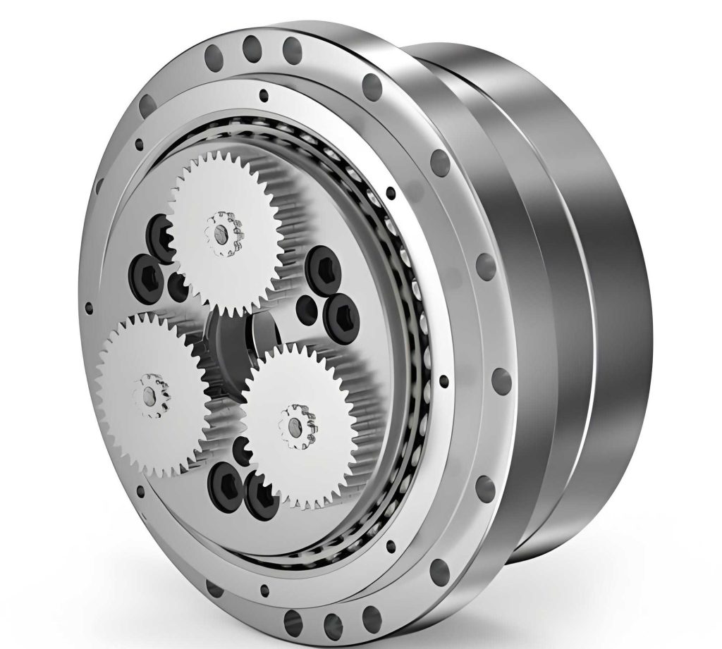
The structure of a typical rotary vector reducer consists of a first-stage planetary gear train and a second-stage cycloid-pin gear mechanism, with the latter providing the major speed reduction. Since the torsional deformation of the first stage is greatly reduced by the high reduction ratio of the second stage, its contribution to the overall torsional stiffness is negligible. Therefore, the total torsional stiffness of the rotary vector reducer is dominated by the stiffness of the second stage, specifically the contact stiffness between the cycloid discs and the needle roller bearings on the crankshafts, and the meshing stiffness between the cycloid discs and the pins.
Modeling the Key Stiffness Components
1. Needle Roller Bearing Stiffness
The three crankshafts, each fitted with a needle roller bearing, support the cycloid disc. The resultant force $ \vec{F} $ from the pin wheel interaction acts on the cycloid disc. This force can be resolved into a tangential component $F_t$ causing rotation and a radial component. For static equilibrium, the reaction forces at the three bearing locations A, B, and C are equal in magnitude:
$$ F_A = F_B = F_C = \frac{F}{3} $$
where $F$ is the magnitude of the resultant force $ \vec{F} $. However, these forces must also provide a balancing torque. Considering the geometry, the radial loads on the three bearings are time-varying and can be expressed as:
$$
\begin{aligned}
\vec{F}_A &= \frac{\vec{F}}{3} + \frac{F_t r’_c}{3a} \begin{Bmatrix} \sin 0^\circ \\ -\cos 0^\circ \end{Bmatrix} \\[6pt]
\vec{F}_B &= \frac{\vec{F}}{3} + \frac{F_t r’_c}{3a} \begin{Bmatrix} \sin 120^\circ \\ -\cos 120^\circ \end{Bmatrix} \\[6pt]
\vec{F}_C &= \frac{\vec{F}}{3} + \frac{F_t r’_c}{3a} \begin{Bmatrix} \sin 240^\circ \\ -\cos 240^\circ \end{Bmatrix}
\end{aligned}
$$
Here, $r’_c$ is the pitch radius of the cycloid disc, $a$ is the eccentricity, and the resultant force vector varies with the crankshaft rotation angle $\theta$:
$$ \vec{F} = F \begin{Bmatrix} \sin(\alpha_c – \theta) \\ \cos(\alpha_c – \theta) \end{Bmatrix} $$
where $\alpha_c$ is the pressure angle. The stiffness of a needle roller bearing is a function of its radial load:
$$ K_{Hc} = 0.34 \times 10^4 \cdot F_r^{0.1} \cdot Z^{0.9} \cdot l^{0.8} \cdot (\cos\alpha)^{1.9} $$
where $F_r$ is the radial load, $Z$ is the number of rollers, $l$ is the effective roller length, and $\alpha$ is the contact angle (0° in this case). The equivalent torsional stiffness contributed by the three time-varying bearing stiffnesses ($K_{HcA}, K_{HcB}, K_{HcC}$) is:
$$ C_{THC} = 2 (K_{HcA} + K_{HcB} + K_{HcC}) \cdot l_c^2 $$
where $l_c$ is the distance from the bearing center to the center of the cycloid disc.
2. Single Tooth Pair Meshing Stiffness
The meshing stiffness between a cycloid tooth and a pin is modeled as a Hertzian contact between two cylinders. A critical parameter is the radius of curvature of the cycloid tooth profile at the contact point, which varies significantly with the meshing phase angle $\theta$:
$$ \rho_i = \frac{r_p (1 + K’^2 – 2K’\cos\theta)^{3/2}}{K'(z_p + 1)\cos\theta – (1 + z_p K’^2)} + r_{rp} $$
In this formula, $r_p$ is the pin center circle radius, $r_{rp}$ is the pin radius, $z_p$ is the number of pins, and $K’ = a z_p / r_p$ is the shortened coefficient. Notably, $\rho_i$ can be positive or negative, indicating convex or concave profile regions, which affects the contact mechanics.
The Hertzian contact deformation for the pin (assumed to have a constant positive curvature $r_{rp}$) and the cycloid tooth (with variable curvature $\rho_i$) are given by:
$$ \delta_z = \frac{4 F_i \rho_c (1 – \mu^2)}{\pi b E r_{rp}}, \quad \delta_c = \frac{4 F_i \rho_c (1 – \mu^2)}{\pi b E |\rho_i|} $$
where $F_i$ is the load at the $i$-th contact point, $\rho_c = \rho_i r_{rp} / (\rho_i + r_{rp})$ is the equivalent curvature radius, $b$ is the tooth width, $E$ is Young’s modulus, and $\mu$ is Poisson’s ratio. The absolute value $|\rho_i|$ is used for the cycloid tooth’s curvature in the deformation formula. The corresponding contact stiffnesses are:
$$ k_z = \frac{F_i}{\delta_z} = \frac{\pi b E r_{rp}}{4\rho_c (1 – \mu^2)}, \quad k_c = \frac{F_i}{\delta_c} = \frac{\pi b E |\rho_i|}{4\rho_c (1 – \mu^2)} $$
The combined mesh stiffness for a single tooth pair is therefore:
$$ K_c = \frac{k_z \cdot k_c}{k_z + k_c} = \frac{\pi b E |\rho_i| (\rho_i – r_{rp})}{4\rho_i (1 – \mu^2) (r_{rp} + |\rho_i|)} $$
Since each meshing point acts at a different moment arm $L_j$ from the center of the cycloid disc, its contribution to the equivalent torsional stiffness is $K_c \cdot L_j^2$. The total equivalent torsional stiffness from $n$ simultaneously engaged tooth pairs on two cycloid discs is:
$$ C_{Tc} = 2 \sum_{j=1}^{n} K_{c_j} \cdot L_{j}^2 $$
The relationship between the single-point equivalent torsional stiffness $K_c \cdot L^2$ and the meshing phase angle $\theta$ is highly nonlinear, as determined by the curvature function $\rho_i(\theta)$ and the moment arm $L(\theta)$.
Overall Torsional Stiffness Model and Experimental Measurement
Within the second-stage reduction mechanism, the equivalent torsional stiffness from the needle roller bearings $C_{THC}$ and the equivalent torsional stiffness from the cycloid-pin meshing $C_{Tc}$ are connected in series. Thus, the overall torsional stiffness $C_W$ of the rotary vector reducer is given by:
$$ C_W = \frac{C_{THC} \cdot C_{Tc}}{C_{THC} + C_{Tc}} $$
To obtain the experimental value for $C_W$, a comprehensive test bench is employed. The input shaft of the rotary vector reducer is fixed, and a precisely controlled torque is applied to the output flange. The corresponding angular displacement is measured using high-resolution encoders. A typical test involves ramping the torque from 0 to the rated torque (e.g., +412 N·m), then down through 0 to the negative rated torque (e.g., -412 N·m), and back to 0, forming a closed hysteresis loop. The average slope of the loading and unloading curves, excluding the backlash region, provides the measured torsional stiffness. For an RV-40E type rotary vector reducer at the rated torque, the measured stiffness $C_{W}^{exp}$ was found to be $3.06 \times 10^8 \text{ N·mm/rad}$.
Inverse Determination of the Meshing Area
With the experimental overall stiffness $C_{W}^{exp}$ and the modeled bearing stiffness $C_{THC}$ (calculated based on the load at the rated torque), the total meshing stiffness $C_{Tc}$ can be derived from the series stiffness model:
$$ C_{Tc}^{derived} = \frac{C_{THC} \cdot C_{W}^{exp}}{C_{THC} – C_{W}^{exp}} $$
For the analyzed case, this derived value was $C_{Tc}^{derived} = 6.24 \times 10^8 \text{ N·mm/rad}$.
The theoretical single-point equivalent torsional stiffness was calculated for all possible 21 pin positions across a 180° meshing phase range. The stiffness values for each pin number are summarized in the table below. The meshing points are contiguous in a properly assembled rotary vector reducer.
| Pin Number | Equivalent Torsional Stiffness (N·mm/rad) | Pin Number | Equivalent Torsional Stiffness (N·mm/rad) |
|---|---|---|---|
| 1 | 0 | 12 | $8.93 \times 10^7$ |
| 2 | $2.20 \times 10^6$ | 13 | $7.33 \times 10^7$ |
| 3 | $1.97 \times 10^7$ | 14 | $5.79 \times 10^7$ |
| 4 | $1.33 \times 10^8$ | 15 | $4.38 \times 10^7$ |
| 5 | $1.84 \times 10^8$ | 16 | $3.12 \times 10^7$ |
| 6 | $1.76 \times 10^8$ | 17 | $2.03 \times 10^7$ |
| 7 | $1.66 \times 10^8$ | 18 | $1.16 \times 10^7$ |
| 8 | $1.52 \times 10^8$ | 19 | $5.25 \times 10^6$ |
| 9 | $1.38 \times 10^8$ | 20 | $1.33 \times 10^6$ |
| 10 | $1.22 \times 10^8$ | 21 | 0 |
| 11 | $1.06 \times 10^8$ |
The goal is to find a contiguous set of pin numbers whose summed equivalent torsional stiffness (from two cycloid discs) most closely matches the derived value $C_{Tc}^{derived}$. By systematically calculating the cumulative stiffness for various contiguous sets, it was found that the set comprising pins 6, 7, 8, and 9 yields a total theoretical stiffness of:
$$ C_{Tc}^{theory} = 2 \times (1.76 + 1.66 + 1.52 + 1.38) \times 10^8 = 6.32 \times 10^8 \text{ N·mm/rad} $$
This value, $6.32 \times 10^8 \text{ N·mm/rad}$, is the closest to the derived value of $6.24 \times 10^8 \text{ N·mm/rad}$. Therefore, the actual meshing area under the rated load corresponds to the meshing phase angle range encompassing pins 6 through 9, which was calculated to be approximately 54° to 81°. This result indicates four simultaneously engaged tooth pairs, which is within the typical desired range and provides a specific, stiffness-validated constraint, unlike the broader traditional assumptions.
Verification via Finite Element Analysis
To validate the theoretically identified meshing area, a finite element analysis (FEA) was conducted. A detailed model of the cycloid disc and pin wheel assembly was created. A torque of 412 N·m was applied to the cycloid disc, and contact elements were defined between the cycloid teeth and all pins. The static structural analysis clearly showed that the primary load path and significant contact pressures were concentrated on pins 6, 7, 8, and 9, with negligible force on the other pins. This FEA result confirmed that the actual meshing area under load is indeed limited to that specific contiguous set of pins, providing strong corroboration for the stiffness-based inverse determination method.
Conclusion
This research presents a novel, indirect method for determining the true meshing area in the cycloid-pin transmission of a rotary vector reducer. The methodology circumvents the impossibility of direct in-situ measurement of engaging tooth pairs by leveraging the global mechanical property of torsional stiffness. The process involves several key steps: first, developing analytical models for the time-varying stiffness of the needle roller bearings and the position-dependent meshing stiffness of the cycloid-pin pairs. Second, formulating the overall torsional stiffness model of the rotary vector reducer by combining these components in series. Third, obtaining the experimental overall stiffness through precision testing on a dedicated test bench. Fourth, using the series model to derive the total meshing stiffness from the experimental data. Finally, and most crucially, identifying the contiguous set of meshing points whose cumulative theoretical stiffness best approximates this derived value, thereby defining the actual load-bearing meshing area.
The successful identification of the meshing area (pins 6-9, corresponding to ~54°-81° phase angle) and its subsequent verification via FEA demonstrates the efficacy and accuracy of this stiffness-based approach. This method provides a powerful and practical tool for engineers. It offers a physically meaningful, measurable constraint—stiffness—that can guide the tooth profile modification process more precisely than assumptions based on fixed phase angle intervals. By ensuring the design modification targets the actual load-carrying teeth, this approach can significantly contribute to optimizing the performance, durability, and precision of the rotary vector reducer, ultimately enhancing the capabilities of the robotic systems that depend on it.