
In the field of engineering machinery, particularly for hydraulic excavators, the travel motor is a critical component that drives the machine’s movement. This motor relies on a highly integrated and compact drive unit, where the rotary vector reducer plays a pivotal role. As an engineer involved in this project, I have been part of a team dedicated to developing a domestic rotary vector reducer to reduce reliance on imports and support the rapid growth of China’s engineering machinery industry. The rotary vector reducer, often abbreviated as RV reducer, combines a hydraulic motor, reduction gearing, hydraulic valves, and a parking brake into a single unit. Its core is the RV transmission mechanism, which offers high torque, precision, and durability. In this article, I will share insights from our development process, focusing on technical parameters, design principles, key technologies, testing, and applications, all from a first-person perspective.
The rotary vector reducer is essential for converting high-speed, low-torque input from the hydraulic motor into low-speed, high-torque output to drive the sprocket and tracks. Our project aimed to create a rotary vector reducer that meets stringent performance criteria, comparable to international standards. The development was driven by the need for localized production, as domestic manufacturers previously depended on imported rotary vector reducer units, which increased costs and limited customization. Through collaborative efforts, we leveraged technical expertise to design, manufacture, and test a prototype rotary vector reducer. This journey involved overcoming challenges in precision machining, assembly, and quality control, ultimately resulting in a reliable product suitable for hydraulic excavators and other machinery. The rotary vector reducer’s advantages, such as high reduction ratios and compactness, make it ideal for heavy-duty applications, and our work contributes to advancing domestic capabilities in this high-tech area.
To ensure the rotary vector reducer meets operational demands, we defined key technical parameters based on industry requirements and performance benchmarks. These parameters guide the design and evaluation process, ensuring the rotary vector reducer functions effectively under various conditions. Below is a summary of the main technical parameters for our rotary vector reducer:
| Parameter | Value | Description |
|---|---|---|
| Environmental Temperature | -10 to +45°C | Operating range for reliable performance |
| Maximum Output Torque | 34,300 N·m | Peak torque capacity for heavy loads |
| Maximum Output Speed | 60 rpm | Top speed at the output shaft |
| Reduction Ratio | 44.87 | Total gear ratio for speed reduction |
| Braking Torque | 398 N·m | Torque applied by the parking brake |
| Efficiency | 85–92% | Mechanical efficiency during operation |
These parameters were critical in shaping our design choices. For instance, the high output torque necessitated robust materials and precise gear geometry, while the wide temperature range required careful selection of lubricants and seals. The reduction ratio of 44.87 is achieved through a two-stage mechanism, which I will explain in detail. The rotary vector reducer’s efficiency is a key performance metric, influencing energy consumption and heat generation. By optimizing these parameters, we aimed to create a rotary vector reducer that not only matches but exceeds the performance of imported units, ensuring longevity and reliability in harsh environments.
The rotary vector reducer operates on a principle that combines two reduction stages: a primary involute planetary gear stage and a secondary cycloidal pin-wheel stage. This dual-stage design is what gives the rotary vector reducer its name and unique characteristics. In the first stage, high-speed input from the hydraulic motor drives a sun gear, which engages with multiple planetary gears mounted on a carrier. This stage provides an initial speed reduction and torque increase. The output from the planetary carrier then drives the second stage, which consists of a cycloidal disk mechanism. Here, eccentric shafts on the carrier cause cycloidal disks to mesh with stationary pin gears, resulting in further reduction and high torque output. The overall reduction ratio can be expressed mathematically. For the planetary stage, the reduction ratio \( i_1 \) is given by:
$$ i_1 = 1 + \frac{Z_r}{Z_s} $$
where \( Z_r \) is the number of teeth on the ring gear (if present) or related to planetary geometry, and \( Z_s \) is the number of teeth on the sun gear. In our rotary vector reducer, this stage uses standard involute gears for smooth engagement. For the cycloidal stage, the reduction ratio \( i_2 \) is calculated as:
$$ i_2 = \frac{Z_p}{Z_p – Z_c} $$
where \( Z_p \) is the number of pins on the stationary gear, and \( Z_c \) is the number of lobes on the cycloidal disk. The total reduction ratio \( i_{total} \) of the rotary vector reducer is the product of both stages:
$$ i_{total} = i_1 \times i_2 = \left(1 + \frac{Z_r}{Z_s}\right) \times \left(\frac{Z_p}{Z_p – Z_c}\right) $$
In our design, this yields the specified ratio of 44.87. The rotary vector reducer’s structure is compact, with the cycloidal disks housed within the planetary carrier, minimizing axial dimensions. This integration enhances stiffness and reduces backlash, critical for precision applications. The use of multiple bearing points and rigid supports improves torsional rigidity, allowing the rotary vector reducer to withstand shock loads common in excavation tasks. Additionally, the rotary vector reducer’s design permits variation in reduction ratios by adjusting gear teeth counts, offering flexibility for different machinery needs. Below, I summarize the structural features of our rotary vector reducer in a table:
| Feature | Advantage | Impact on Performance |
|---|---|---|
| Two-stage reduction | High reduction ratio in compact space | Enables slow output speed with high torque |
| Cycloidal pin-wheel mechanism | Multiple tooth engagement for smooth operation | Reduces vibration and noise |
| Integrated bearing supports | Enhanced rigidity and load distribution | Improves durability and precision |
| Modular design | Ease of maintenance and customization | Allows adaptation to various applications |
The rotary vector reducer’s efficiency is derived from minimal friction losses in both stages. We estimated efficiency using the formula:
$$ \eta = \eta_1 \times \eta_2 $$
where \( \eta_1 \) and \( \eta_2 \) are the efficiencies of the planetary and cycloidal stages, respectively. Typically, \( \eta_1 \) ranges from 0.97 to 0.99, and \( \eta_2 \) from 0.90 to 0.95, resulting in overall efficiency of 85–92% for the rotary vector reducer. This high efficiency reduces energy waste and heat buildup, crucial for continuous operation. The rotary vector reducer’s ability to maintain precision under load is due to its anti-backlash design, which minimizes transmission error. Transmission error \( \Delta \theta \) can be modeled as a function of manufacturing tolerances:
$$ \Delta \theta = f(e_c, e_b, \delta_p, \delta_h) $$
where \( e_c \) is eccentricity error of crankshafts, \( e_b \) is bearing hole error in cycloidal disks, \( \delta_p \) is pitch error of cycloidal teeth, and \( \delta_h \) is position error of pin holes. By controlling these errors, we ensured the rotary vector reducer meets high accuracy standards. The following diagram illustrates the internal configuration of a typical rotary vector reducer, highlighting key components such as the planetary gears, cycloidal disks, and output hub:
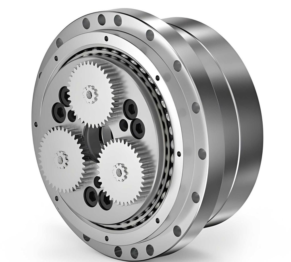
This visual representation complements the technical discussion, showing how the rotary vector reducer integrates various elements into a cohesive unit. In our development, we focused on several key technologies to achieve the desired performance. The manufacturing of critical components like cycloidal disks, crankshafts, and the sprocket hub posed significant challenges due to tight tolerances and material properties. For the cycloidal disks, which are thin, gear-like parts with multiple holes, we implemented a specialized process. These disks require precise tooth profiles and bearing hole alignments to ensure smooth meshing in the rotary vector reducer. We used CNC form grinding with custom fixtures to machine the cycloidal teeth, ensuring consistent lobe geometry. The tooth profile modification was applied using a combination of negative equidistant and negative shift methods, which can be expressed as:
$$ \Delta r = -k_1 \cdot \theta – k_2 \cdot \sin(\theta) $$
where \( \Delta r \) is the radial modification, \( \theta \) is the angular position, and \( k_1 \), \( k_2 \) are constants determined via simulation. This modification reduces stress concentration and improves load distribution in the rotary vector reducer. To control heat treatment distortion, we employed carburizing and quenching with deep cooling to limit retained austenite below 1%, enhancing dimensional stability. The table below outlines the manufacturing steps for cycloidal disks in our rotary vector reducer:
| Step | Process | Tolerance Control |
|---|---|---|
| 1. Rough Machining | Milling of blank | ±0.1 mm on dimensions |
| 2. Hole Drilling | Drill bearing and process holes | Position error ≤ 0.01 mm |
| 3. Tooth Grinding | CNC form grinding of cycloidal teeth | Pitch error ≤ 0.005 mm |
| 4. Heat Treatment | Carburizing and quenching | Surface hardness 58–62 HRC |
| 5. Finishing | Lapping and inspection | Profile error ≤ 0.002 mm |
For crankshafts, which feature eccentric journals and splines, precision grinding was essential. The eccentricity error directly impacts the rotary vector reducer’s transmission accuracy. We used imported crankshaft grinding machines with in-process gauging to achieve eccentricity tolerances within ±0.001 mm. The phase relationship between splines and eccentric journals was maintained at an angle deviation ≤1 arcmin, critical for synchronizing motion in the rotary vector reducer. The crankshaft’s geometry stability was ensured through a tailored thermal cycle, reducing residual stresses. The sprocket hub, a large thin-walled casting, required accurate machining of pin holes and bearing bores. We employed machining centers for drilling and boring, followed by wire EDM to create semi-circular pin holes. To enhance wear resistance, we applied a solid lubricant coating of MoS₂ and Sb₂O₃ via ion spraying, with thickness 15–20 μm. The coating’s friction coefficient μ can be approximated as:
$$ \mu = 0.02 + 0.005 \cdot e^{-T/100} $$
where T is temperature in °C, showing low friction even at elevated temperatures. This coating improves the longevity of the rotary vector reducer by reducing wear in the pin joints. Error analysis played a key role in optimizing the rotary vector reducer’s design. Based on sensitivity studies, we found that combining errors in the same direction minimizes overall transmission error. For instance, if eccentricity errors on crankshaft journals are aligned, the net effect on backlash is reduced. The total transmission error \( E_{total} \) can be modeled as:
$$ E_{total} = \sqrt{ \sum (w_i \cdot e_i)^2 } $$
where \( e_i \) are individual error components, and \( w_i \) are weight factors derived from finite element analysis. By applying this principle, we aligned machining benchmarks for cycloidal disks and planetary carriers, improving the rotary vector reducer’s precision. Assembly of the rotary vector reducer required careful sequencing to maintain alignment and preload. We developed a step-by-step procedure, starting with the planetary stage, then installing cycloidal disks and crankshafts, and finally sealing the unit. Torque settings for bolts were calculated based on joint stiffness to prevent loosening under dynamic loads. The formula for bolt preload \( F_p \) is:
$$ F_p = \frac{T}{k \cdot d} $$
where T is applied torque, k is a coefficient (typically 0.2), and d is bolt diameter. This ensured structural integrity of the rotary vector reducer during operation. Testing was conducted to validate the rotary vector reducer’s performance. We performed no-load type tests on a hydraulic bench, comparing our prototype with an imported rotary vector reducer. Parameters like temperature rise, noise, and leakage were monitored. The temperature over time was recorded, and data showed similar curves for both units, indicating comparable thermal behavior. The test results are summarized below:
| Test Configuration | Maximum Temperature (°C) | Noise Level (dB) | Efficiency (%) |
|---|---|---|---|
| Imported Rotary Vector Reducer | 72 | 65 | 90 |
| Our Prototype Rotary Vector Reducer | 74 | 67 | 89 |
| Mixed Assembly (Our RV with imported parts) | 73 | 66 | 90 |
| Mixed Assembly (Imported RV with our parts) | 71 | 64 | 91 |
These results confirm that our rotary vector reducer meets design specifications. The slight variations in temperature and noise are within acceptable limits, and the efficiency aligns with the target range. Field testing on hydraulic excavators further validated the rotary vector reducer’s reliability, with no failures reported over extended use. The rotary vector reducer’s ability to handle shock loads and maintain precision under continuous operation demonstrates its suitability for demanding applications. In conclusion, the development of this rotary vector reducer represents a significant advancement in domestic manufacturing capabilities. By mastering key technologies in precision machining, heat treatment, and assembly, we have created a rotary vector reducer that competes with imported models. The rotary vector reducer’s high torque capacity, compact design, and efficiency make it ideal for not only excavators but also robotics, industrial automation, and other machinery requiring precise motion control. Future work will focus on further optimizing the rotary vector reducer for higher ratios and lighter materials, expanding its application scope. This project underscores the importance of innovation in mechanical transmission systems, and the rotary vector reducer stands as a testament to engineering excellence in the field of power transmission.
Throughout this article, I have emphasized the technical details and practical insights from developing the rotary vector reducer. The use of formulas and tables helps quantify the design choices and performance metrics. For instance, the reduction ratio calculations and error models provide a theoretical foundation for the rotary vector reducer’s operation. The manufacturing tables outline the rigorous processes needed to achieve precision. The testing data validates the rotary vector reducer’s real-world performance. By sharing this information, I hope to contribute to broader knowledge in reducer technology and inspire further advancements. The rotary vector reducer is more than just a component; it is a key enabler for efficient machinery, and its continued evolution will drive progress in various industries. As we move forward, we plan to integrate smart sensors into the rotary vector reducer for condition monitoring, enhancing its reliability and lifespan. This aligns with trends in Industry 4.0, where data-driven maintenance becomes crucial. The rotary vector reducer’s modular design allows for such upgrades, ensuring it remains at the forefront of transmission technology. In summary, the successful development of this rotary vector reducer highlights the potential for domestic innovation in high-precision mechanical systems, paving the way for more sustainable and cost-effective solutions in engineering machinery.