
The pursuit of high precision in motion control systems, particularly within robotics and advanced automation, has placed stringent demands on power transmission components. Among these, the rotary vector reducer has emerged as a superior solution, distinguished by its exceptional combination of high reduction ratio, compactness, robust torsional rigidity, and high torque capacity. As the critical interface between servo motors and robotic joints, its performance directly dictates the positioning accuracy, repeatability, and dynamic response of the entire system. Consequently, the study of rotary transmission error (RTE)—the deviation between the actual and theoretically commanded output rotation—in rotary vector reducers has become a paramount research focus. This article synthesizes the current state of research on this topic, focusing on the methodologies and key findings that illuminate the complex error mechanisms inherent in the multi-stage, multi-component architecture of the rotary vector reducer.
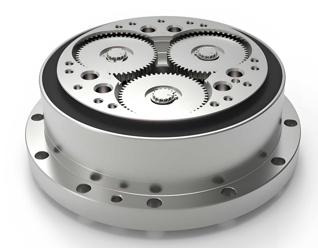
Fundamentally, the rotary vector reducer is a two-stage hybrid gear system. The first stage is typically a conventional involute planetary gear train, providing an initial speed reduction. The second, core stage is a cycloidal drive, derived from the classic摆线针轮 (cycloid pinwheel) principle but enhanced with multiple crankshafts and cycloid discs. The output is realized through a cam mechanism or pin gear connected to these crankshafts. This unique design is responsible for the high rigidity and compact size of the rotary vector reducer. The following illustration provides a clear view of its intricate internal assembly, highlighting the interplay between the planetary stage, the dual cycloid discs, the crankshafts, and the output pins.
Understanding and quantifying the rotary transmission error in such a system requires dissecting the influence of myriad manufacturing tolerances and assembly errors from both geometric and dynamic perspectives.
Geometric Analysis of Transmission Error in Cycloidal Drives
Early foundational work on the precision of cycloidal drives, which form the heart of the rotary vector reducer, approached the problem from a purely geometrical standpoint. This methodology focuses on deriving closed-form expressions for kinematic error based on specific dimensional deviations.
The analysis begins with the ideal mathematical model of the cycloid disc profile. The coordinates of a point on the cycloid disc relative to its center are given by:
$$ x = R_p \sin(\theta) – r_p \sin(\theta + \phi) – a \sin(i \theta) $$
$$ y = R_p \cos(\theta) – r_p \cos(\theta + \phi) – a \cos(i \theta) $$
where $R_p$ is the pin circle radius, $r_p$ is the pin (or roller) radius, $a$ is the eccentricity (crank radius), $i$ is the gear ratio (number of pins vs. lobes), $\theta$ is the input crank angle, and $\phi$ is related to the trochoid ratio.
A primary error source considered is a uniform deviation in the pin radius, $\Delta r_p$. This error effectively alters the theoretical tooth profile of the cycloid disc. The geometric method calculates two consequential error components:
- Transmission Error (Lag Angle, $\Delta \theta_L$): The instantaneous difference between the actual output position and the position predicted by the ideal kinematics during loaded operation. It represents the dynamic positioning inaccuracy.
$$ \Delta \theta_L = f_{geom}(\theta, \Delta r_p, R_p, a, i) $$ - Backlash (Lead Angle, $\Delta \theta_B$): The free rotation possible when the driving torque is removed, representing lost motion due to clearance. This is the primary contributor to non-repeatable error in a rotary vector reducer.
The total positional error or lost motion $\Delta \theta$ is often considered as the sum:
$$ \Delta \theta \approx \Delta \theta_L + \Delta \theta_B $$
Key conclusions from this geometric line of inquiry for a single-stage, single-cycloid-disc system—a simplified analogue to the second stage of a rotary vector reducer—include:
- Both $\Delta \theta_L$ and $\Delta \theta$ exhibit periodic fluctuation with a period of $2\pi/(i+1)$, where $i$ is the high-stage reduction ratio of the cycloid drive.
- The instantaneous transmission ratio $i_{inst}$ also fluctuates with the same period, inducing torsional vibration in the output.
- Parametric studies reveal the sensitivity of error and vibration to design parameters like pin circle diameter error and nominal gear ratio.
While elegant and insightful, this geometric approach faces significant limitations when applied to a full rotary vector reducer: it struggles to account for the simultaneous action of multiple, diverse error sources, the force-dependent deformations in a preloaded system, and the complex interactions between two cycloid discs, multiple crankshafts, and the two distinct transmission stages.
Dynamic System Modeling for the Complete Rotary Vector Reducer
To overcome the limitations of pure geometric analysis, a more comprehensive method employs lumped-parameter dynamic modeling. This approach treats each major component of the rotary vector reducer (input gear, planet carrier, crankshafts, cycloid discs, output plate) as a rigid body with mass and inertia. The compliances and contacts between these bodies—such as gear mesh stiffness, bearing stiffness, and the contact stiffness between cycloid disc lobes and pins—are modeled as linear or nonlinear springs. Manufacturing and assembly errors are introduced as equivalent displacement excitations at the appropriate spring connections or as geometric offsets in the kinematic constraints.
A typical dynamic model for a rotary vector reducer with three crankshafts and two cycloid discs may involve 15-20 degrees of freedom. The general matrix equation of motion under a static load (to ensure contact conditions) can be written as:
$$ \mathbf{M}\ddot{\mathbf{q}} + \mathbf{C}\dot{\mathbf{q}} + \mathbf{K}(t, \mathbf{q}, \mathbf{e})\mathbf{q} = \mathbf{F}_{ext} + \mathbf{F}_{err}(\mathbf{e}) $$
where $\mathbf{q}$ is the vector of generalized coordinates (rotations/translations of components), $\mathbf{M}$ is the mass matrix, $\mathbf{C}$ is the damping matrix, $\mathbf{K}$ is the time-varying stiffness matrix dependent on the contact conditions and error vector $\mathbf{e}$, $\mathbf{F}_{ext}$ is the external load, and $\mathbf{F}_{err}$ represents forces induced by errors $\mathbf{e}$.
By solving this system, often iteratively for quasi-static conditions, the actual output rotation $\theta_{out}^{actual}$ for a given input $\theta_{in}$ is obtained. The rotary transmission error $\epsilon$ is then:
$$ \epsilon = \theta_{out}^{actual} – \frac{\theta_{in}}{i_{total}} $$
where $i_{total}$ is the total design reduction ratio of the rotary vector reducer.
Synthesis of Key Findings on Error Influences
Research using the dynamic modeling methodology has yielded critical insights into the relative impact of various imperfections on the overall precision of a rotary vector reducer. These findings are summarized below, categorizing errors by their source component.
| Error Source | Component Affected | Typical Influence on RTE Magnitude | Remarks |
|---|---|---|---|
| Eccentricity Error of Crankshafts | Second Stage (Cycloid Drive) | High | Especially critical if eccentricity differs between the three crankshafts. |
| Circumferential Position Error of Crankshafts | Second Stage (Cycloid Drive) | High | Affects the phasing of force transmission through the discs. |
| Cumulative Pitch Error of Cycloid Disc | Second Stage (Cycloid Drive) | High | A primary driver of kinematic error. Phase difference between the two discs is crucial. |
| Pin Gear Cumulative Pitch Error | Second Stage (Cycloid Drive) | High | Directly alters the contact kinematics. |
| Radial Error of Crank Holes in Cycloid Disc | Second Stage (Cycloid Drive) | Moderate | Less sensitive than circumferential hole errors. |
| Circumferential Error of Crank Holes | Second Stage (Cycloid Drive) | High | Severe impact, akin to crankshaft position error. |
| Profile Error (e.g., $\Delta r_p$) of Cycloid Disc | Second Stage (Cycloid Drive) | Low (Alone), High (Combined) | Negligible alone if kept under ~5 µm, but amplifies other errors significantly. |
| Eccentricity Error of Output Pin Gear/Plate | Output Stage | High | Directly manifests as output runout. |
| Errors in Involute Planet Gear Stage | First Stage | Low | Greatly attenuated by the high reduction of the second stage. Not a primary concern for final output RTE. |
The Critical Role of Error Phasing and Combined Effects
A paramount conclusion from dynamic studies is that the rotary transmission error of a complete rotary vector reducer cannot be predicted by simply summing the effects of individual errors. The phase relationships between errors on different components, and particularly between the two cycloid discs, are decisive. Strategic “error phasing” can be used as a compensation technique during assembly.
For instance, consider the cumulative pitch error of the two cycloid discs. If these errors are assembled in phase (i.e., the thickest lobe of one disc aligns with the thickest lobe of the other), their effects partially cancel due to the symmetric force flow through the two discs. Conversely, if assembled 180° out of phase, the errors reinforce, leading to a significantly larger RTE. Similar principles apply to the phasing of crank hole errors between discs.
The table below illustrates the dramatic effect of error phasing on the resultant RTE in a dual-cycloid disc rotary vector reducer.
| Error Type | Phase Relationship Between Discs | Effect on Composite RTE |
|---|---|---|
| Cumulative Pitch Error | In Phase (0° separation) | Partial cancellation. Lower RTE amplitude. |
| Out of Phase (180° separation) | Reinforcement. Higher RTE amplitude. | |
| Crank Hole Circumferential Error | Identical direction | Effects add, increasing RTE. |
| Opposite direction | Effects may compound in a complex manner, often worsening RTE. | |
| Theoretical Tooth Profile Radius Error | Same sign (both discs larger/smaller) | Moderate effect on backlash. |
| Opposite signs (one larger, one smaller) | Severe effect, creating significant load asymmetry and high RTE. |
This underscores that precision in a rotary vector reducer is not solely a function of tighter machining tolerances, but also of intelligent tolerance allocation and controlled assembly processes that manage the phase of unavoidable errors.
Comparative Summary of Methodologies
The geometric and dynamic approaches offer complementary insights into the problem of rotary transmission error in rotary vector reducers.
| Aspect | Geometric/Kinematic Method | Dynamic/Lumped-Parameter Method |
|---|---|---|
| Primary Focus | Idealized kinematics with single error inputs. Calculation of backlash and kinematic error. | System-level behavior under load, including multiple simultaneous errors and elastic deformations. |
| System Complexity | Best for single-stage, single-cycloid analysis. Struggles with full RV reducer complexity. | Capable of modeling full two-stage RV reducer with multiple crankshafts and cycloid discs. |
| Error Handling | Analytical formulas for specific error types (e.g., $\Delta r_p$). Difficult for combined errors. | Can incorporate a wide array of machining and assembly errors simultaneously and study interactions. |
| Outputs | Closed-form expressions for error components. Clear parametric trends. | Time-domain or frequency-domain RTE, load distribution, torsional vibration, component deflections. |
| Main Utility | Fundamental understanding, preliminary design guidance, sensitivity analysis of design parameters. | Precision prediction for specific designs, tolerance analysis, assembly guidance, and design optimization. |
Conclusions and Future Directions
The pursuit of ultra-high precision in rotary vector reducers hinges on a deep and systematic understanding of rotary transmission error. Research to date has successfully transitioned from analyzing simplified geometric models to employing sophisticated dynamic system models that capture the intricate reality of these mechanisms. The key synthesized learnings are:
- The first (planetary) stage errors have minimal direct impact on the final output RTE of the rotary vector reducer, allowing for more relaxed tolerances there.
- The second (cycloidal) stage is the critical domain for precision. Dominant error sources include crankshaft eccentricity/positioning, cycloid disc pitch error, and pin gear pitch error.
- The combined effect of multiple errors is non-linear and cannot be linearly superimposed. The interaction between errors, such as a small profile error amplifying the effect of a pitch error, is significant.
- Error phasing, especially between the two cycloid discs, is a powerful factor. Controlled assembly to achieve favorable error phasing can compensate for a substantial portion of manufacturing variability, reducing the need for prohibitively expensive ultra-high-precision machining for all components.
- The use of dual cycloid discs inherently averages and reduces RTE, but this benefit is fully realized only when their errors are favorably phased.
Future research directions are likely to involve more advanced multi-body dynamic simulations incorporating nonlinear contact mechanics and thermal effects, integrated with robust design and tolerance optimization algorithms. Furthermore, the development of in-process or post-assembly adjustment mechanisms to actively tune error phasing could represent a breakthrough in achieving consistent, ultra-high precision in rotary vector reducers for the most demanding robotic and aerospace applications. The ultimate goal remains to refine the design, manufacturing, and assembly of the rotary vector reducer to push the boundaries of achievable motion fidelity.