
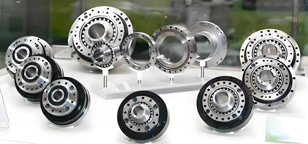
The pursuit of high-precision motion control in advanced manufacturing, robotics, and automation has consistently driven the development of specialized transmission systems. Among these, the Rotary Vector (RV) reducer stands out as a pivotal component. Characterized by a two-stage compact structure combining a primary planetary gear stage and a secondary cycloid-pin gear stage, the RV reducer offers exceptional advantages, including high reduction ratios, substantial torque capacity, excellent torsional rigidity, and compactness. Its performance is crucial in applications where precise positional accuracy and repeatability are non-negotiable, such as in industrial robot joints, CNC rotary tables, and precision medical equipment.
The transmission accuracy, defined as the deviation between the theoretical and actual output position for a given input, is the ultimate metric for evaluating the performance of a precision rotary vector reducer. This accuracy is not an inherent property of the design alone but is profoundly influenced by the cumulative effect of numerous microscopic imperfections introduced during manufacturing and assembly. These imperfections, or error factors, encompass dimensional tolerances, gear tooth profile deviations, bearing clearances, and eccentricities in rotating components. A critical challenge in designing a high-performance rotary vector reducer is identifying which of these myriad error sources have the most pronounced effect on the final output error. This process, known as sensitivity analysis, provides invaluable guidance for allocating manufacturing tolerances and focusing quality control efforts where they matter most.
This article presents a comprehensive study on the sensitivity of transmission accuracy to various error factors in an rotary vector reducer. We move beyond static or single-factor analyses by establishing a nonlinear multi-body dynamic model that holistically integrates the effects of part machining errors, assembly misalignments, and bearing clearances. The dynamic transmission error is then solved numerically, and its sensitivity to each individual error factor is rigorously quantified using a numerical differentiation method. The core objective is to distill, from the complex web of potential errors, the key sensitivities that dominate the kinematic performance of the rotary vector reducer. The findings offer a targeted roadmap for the design and manufacture of ultra-high-precision RV transmissions.
1. Mathematical Modeling for Dynamic Transmission Accuracy
To accurately capture the interplay of forces and motions within an rotary vector reducer under the influence of errors, a detailed nonlinear dynamic model is essential. The model treats the system as a collection of rigid bodies (gears, crankshafts, carrier) connected by nonlinear spring-damper elements representing gear mesh stiffnesses and bearing contact stiffnesses.
1.1 Mechanical Model and Generalized Coordinates
The system’s dynamic state is described using a set of generalized coordinates representing small displacements (linear and angular) of each component from its ideal theoretical position. These micro-displaceances are crucial for calculating the relative deformations at contact points.
- Sun Gear: Translational displacements \(X_s\), \(Y_s\) in the fixed coordinate plane.
- Planet Gears & Crank Shafts (i=1,2,3): Translational displacements \(X_{pi}\), \(Y_{pi}\) and rotational displacement \(\theta_{pi} – \theta_p\), where \(\theta_p\) is the theoretical planet rotation.
- Cycloid Gears (j=1,2): Radial displacement \(\eta_{dj}\) relative to its own center, rotational displacement \(\theta_{dj} – \theta_c\) (relative to carrier), and rotational displacement \(\theta_{doj} – \theta_p\) (relative to planet). \(\theta_c\) is the theoretical carrier rotation.
- Output Carrier: Translational displacements \(X_{ca}\), \(Y_{ca}\) and rotational displacement \(\theta_{ca} – \theta_c\).
The stiffness elements in the model include:
$$ k_{spi} \text{ (sun-planet mesh)}, \quad k_{djk} \text{ (cycloid-pin mesh)}, $$
$$ k_{dcji} \text{ (cycloid-crank bearing)}, \quad k_{bi} \text{ (crank-carrier bearing)}, $$
$$ k_{ca} \text{ (carrier-housing bearing)}, \quad k_s \text{ (sun gear support)}. $$
The bearing stiffnesses \(k_{dcji}, k_{bi}, k_{ca}\) and the cycloid-pin mesh stiffness \(k_{djk}\) are typically nonlinear, calculated using Hertzian contact theory (e.g., Palmgren’s formula) and are functions of the load. The gear mesh stiffness \(k_{spi}\) is derived from tooth bending deformation, and \(k_s\) from sun shaft deflection.
1.2 Description of Error Factors
Each potential source of error is modeled as a displacement excitation in the force-deformation relationships. Errors are characterized by a magnitude and a phase/orientation angle.
Gear Errors:
- Sun/Planet gear: Base circle eccentricity \((E_s, \beta_s)\), \((E_{pi}, \beta_{pi})\).
- Cycloid gear: Tooth space deviation \(R_{djk}\), Cumulative pitch deviation \(AP_{djk}\), Crank hole eccentricity \((E_{hji}, \beta_{hji})\).
- Pin gear: Tooth space deviation \(R_{jk}\), Cumulative pitch deviation \(AP_{jk}\), Pin diameter error \(\delta_{jk}\), Pin radius error \(\delta_{thjk}\).
Assembly & Component Errors:
- Sun gear/Carrier assembly error: \((A_s, \gamma_s)\), \((A_c, \gamma_c)\).
- Crank eccentric cam error: \((E_{cji}, \beta_{cji})\).
- Carrier crank hole eccentricity: \((E_{cai}, \beta_{cai})\).
Clearances:
- Bearing clearances: \(\delta_{bji}\) (cycloid-crank), \(\delta_{xi}, \delta_{yi}\) (crank-carrier), \(\delta_{ca}\) (carrier-housing).
1.3 Force Formulations at Contact Interfaces
The interaction forces at each contact are derived from the relative displacement between components, which includes both the generalized micro-displaceances and the injected error terms. A positive force indicates compression.
1. Sun Gear Support Forces:
$$ P_{sx} = k_s (X_s – A_s \cos \gamma_s) $$
$$ P_{sy} = k_s (Y_s – A_s \sin \gamma_s) $$
2. Sun-Planet Mesh Force (Planet i):
The force acts along the line of action. The relative approach \(\delta_{spi}\) is:
$$ \delta_{spi} = X_s \cos A_i + Y_s \sin A_i – X_{pi} \cos A_i – Y_{pi} \sin A_i – R_{bp}(\theta_{pi} – \theta_p) + E_s \cos(\theta_s + \beta_s – A_i) – E_{pi} \cos(\beta_{pi} – \theta_p – A_i) $$
$$ \text{where } A_i = \theta_c + \varphi_i + \pi/2 – \alpha’, \quad \alpha’ \text{ is operating pressure angle.} $$
Thus, the mesh force is \(P_{spi} = k_{spi} \cdot \delta_{spi}\).
3. Cycloid Gear – Crank Shaft Bearing Forces (Component j on Planet i):
These are resolved into X and Y components. The relative displacements include eccentricity errors and clearances with a sign (\(\pm\)) determined by contact condition.
$$
\begin{aligned}
P_{dcjix} &= k_{dcji} \big[ X_{pi} – R_e \theta_{pi} \sin(\theta_p+\psi_j) – \eta_{dj} \cos(\theta_p+\psi_j) + R_{dc}(\theta_{dj}-\theta_c)\sin(\theta_c+\varphi_i) \\
&\quad + R_e \theta_{doj} \sin(\theta_p+\psi_j) – E_{hji}\cos(\theta_c+\varphi_i+\beta_{hji}) + E_{cji}\cos(\theta_p+\psi_j+\beta_{cji}) \pm \delta_{bji} \big] \\
P_{dcjiy} &= k_{dcji} \big[ Y_{pi} – R_e \theta_{pi} \cos(\theta_p+\psi_j) + \eta_{dj} \sin(\theta_p+\psi_j) + R_{dc}(\theta_{dj}-\theta_c)\cos(\theta_c+\varphi_i) \\
&\quad + R_e \theta_{doj} \cos(\theta_p+\psi_j) – E_{hji}\sin(\theta_c+\varphi_i+\beta_{hji}) + E_{cji}\sin(\theta_p+\psi_j+\beta_{cji}) \pm \delta_{bji} \big]
\end{aligned}
$$
4. Cycloid-Pin Tooth Mesh Force (Pin k on Cycloid j):
The force acts along the common normal at the contact point.
$$
\begin{aligned}
P_{dijk} &= k_{djk} \big[ \eta_{dj} \cos\alpha_{jk} – R_d (\theta_{dj}-\theta_c) \sin\alpha_{jk} + R_e (\theta_{doj}-\theta_p) \sin\alpha_{jk} \\
&\quad – R_{jk} \cos(\alpha_{jk} – \phi_{ijk}) – AP_{jk} \sin(\alpha_{jk} – \phi_{ijk}) \\
&\quad + R_{djk} \cos(\alpha_{jk} – \phi_{djk}) + AP_{djk} \sin(\alpha_{jk} – \phi_{djk}) – \delta_{jk} – \delta_{thjk} \big]
\end{aligned}
$$
5. Crank Shaft – Carrier Bearing Forces (Planet i):
$$
\begin{aligned}
P_{ocix} &= k_{bi} \big[ X_{pi} + R_{dc}(\theta_{ca}-\theta_c)\sin(\theta_c+\varphi_i) – X_{ca} – E_{cai}\cos(\theta_c+\varphi_i+\beta_{cai}) \pm \delta_{xi} \big] \\
P_{ociy} &= k_{bi} \big[ Y_{pi} – R_{dc}(\theta_{ca}-\theta_c)\cos(\theta_c+\varphi_i) – Y_{ca} – E_{cai}\sin(\theta_c+\varphi_i+\beta_{cai}) \pm \delta_{yi} \big]
\end{aligned}
$$
6. Carrier – Housing Bearing Forces:
$$ P_{cax} = k_{ca}(X_{ca} – A_c \cos \gamma_c \pm \delta_{ca}) $$
$$ P_{cay} = k_{ca}(Y_{ca} – A_c \sin \gamma_c \pm \delta_{ca}) $$
1.4 Dynamic Equations of Motion and Solution
Applying D’Alembert’s principle to each component (sun gear, planets, cycloids, carrier) by balancing inertial, damping, and the aforementioned forces leads to a system of coupled, second-order nonlinear differential equations. The general form for a component with mass \(m\) and moment of inertia \(I\) is:
$$ m\ddot{q} + c\dot{q} + F_{elastic}(q, \dot{q}, t) = 0 $$
where \(q\) represents its generalized coordinates and \(F_{elastic}\) is the sum of all elastic contact forces acting on it, which are nonlinear functions of displacements and errors.
Assuming constant input speed to the sun gear and neglecting friction, the system is solved for the time-domain response of all coordinates, particularly the output carrier rotation \(\theta_{ca}(t)\). The dynamic transmission error \(\Delta\theta_{ca}(t)\) is then:
$$ \Delta\theta_{ca}(t) = \theta_{ca}(t) – \theta_c(t) $$
where \(\theta_c(t)\) is the ideal, rigid-body output rotation. Due to the nonlinear stiffness and clearance-induced impacts, a direct numerical integration scheme is required. The implicit Newmark-β method (with parameters for numerical stability) is employed to solve this complex system.
2. Methodology for Sensitivity Analysis
Sensitivity analysis quantifies how the system’s performance metric changes in response to variations in its input parameters (error factors).
First, we define the Transmission Accuracy Metric \(\Delta\theta_{er}\). It is the peak-to-peak value of the dynamic transmission error over one full output revolution under steady-state operating conditions:
$$ \Delta\theta_{er} = \max | \Delta\theta_{ca}(t) | – \min | \Delta\theta_{ca}(t) | \quad \text{for } 0 \le \theta_c \le 2\pi $$
A smaller \(\Delta\theta_{er}\) indicates higher transmission accuracy.
Let the vector \(\mathbf{X} = (x_1, x_2, …, x_k)^T\) represent all \(k\) error factors under consideration (e.g., \(x_1=E_s, x_2=R_{jk}, …\)). The transmission accuracy is a function of these factors: \(\Delta\theta_{er} = f(\mathbf{X})\).
The Sensitivity Vector \(\mathbf{S}\) is the gradient of this function:
$$ \mathbf{S} = \nabla f = \left[ \frac{\partial f}{\partial x_1}, \frac{\partial f}{\partial x_2}, …, \frac{\partial f}{\partial x_k} \right]^T = [S_1, S_2, …, S_k]^T $$
The component \(S_i\), the sensitivity with respect to error factor \(x_i\), measures the local rate of change of transmission error per unit change in \(x_i\). A large absolute value \(|S_i|\) indicates high sensitivity—the accuracy is strongly affected by that particular error.
Since the function \(f\) is implicit and results from a dynamic simulation, analytical derivatives are intractable. We employ the Five-Point Numerical Differentiation Method to compute each \(S_i\):
- Hold all other error factors \(x_j (j \ne i)\) constant at their nominal (or mean) values.
- Perturb the factor \(x_i\) within a realistic range (e.g., ±10% of its nominal magnitude).
- Select five equally spaced points within this perturbation interval: \(x_i^{(1)}, x_i^{(2)}, x_i^{(3)}, x_i^{(4)}, x_i^{(5)}\).
- Run the dynamic model for each of these five values to compute the corresponding transmission accuracies: \(f^{(1)}, f^{(2)}, f^{(3)}, f^{(4)}, f^{(5)}\).
- Apply the five-point stencil formula for the first derivative (central difference for interior points, forward/backward for endpoints) to approximate \(S_i\):
$$ S_i \approx \frac{-f^{(5)} + 8f^{(4)} – 8f^{(2)} + f^{(1)}}{12h} \quad \text{(for interior point evaluation)} $$
where \(h\) is the spacing between points. The process is repeated around the nominal value to get the final sensitivity.
The sign of \(S_i\) is significant: \(S_i > 0\) implies transmission error increases as the error factor increases (e.g., larger clearance worsens accuracy); \(S_i < 0\) implies an inverse relationship.
3. Case Study: RV-80E Reducer Analysis
We apply the developed model and sensitivity method to a representative RV-80E type rotary vector reducer. Its major design parameters are listed below:
| Parameter | Stage 1: Planetary | Stage 2: Cycloidal | ||
|---|---|---|---|---|
| Reduction Ratio | 81 | |||
| Gear | Sun | Planet | Cycloid Disc | Pin Gear |
| Number of Teeth | 16 | 32 | 39 | 40 |
| Module (mm) | 1.75 | 1.75 | – | – |
| Face Width (mm) | 7.0 | 7.0 | 12 | 24 |
| Pressure Angle (°) | 20 | – | – | |
| Profile Shift Coefficient | 0.519 | -0.555 | – | – |
| Pin Circle Radius (mm) | – | – | – | 76.5 |
| Pin Radius (mm) | – | – | – | 3.0 |
| Eccentricity (mm) | – | – | 1.5 | – |
The stiffness values, which are load-dependent, are characterized by their base coefficients as shown in the table below. The exponent of 0.1 for some stiffnesses reflects the nonlinear Hertzian contact relationship (Force ∝ Stiffness ⋅ Deformation^{1.1}).
| Stiffness Element | Symbol | Base Value / Formula |
|---|---|---|
| Sun Gear Support | \(k_s\) | \(1.23 \times 10^5\) N/mm |
| Sun-Planet Mesh | \(k_{spi}\) | \(1.58 \times 10^5\) N/mm |
| Cycloid-Crank Bearing | \(k_{dcji}\) | \(1.93 \times 10^5 \cdot P_{dcji}^{0.1}\) N/mm |
| Crank-Carrier Bearing | \(k_{bi}\) | \(2.27 \times 10^5 \cdot P_{oci}^{0.1}\) N/mm |
| Cycloid-Pin Mesh | \(k_{djk}\) | \(1.93 \times 10^5 \cdot P_{dijk}^{0.1}\) N/mm |
| Carrier-Housing Bearing | \(k_{ca}\) | \(2.15 \times 10^5 \cdot P_{ca}^{0.1}\) N/mm |
For the sensitivity study, we focus on error factors identified as potentially significant for the cycloidal stage, which is the primary source of high reduction ratio and a likely sensitivity hotspot. The nominal magnitude for most error perturbations is set to a representative value ‘e’, varied from 0.5 to 15 μm. The specific error configurations are:
| Error Factor | Component | Phase Angle \(\beta\) or Pattern |
|---|---|---|
| Cycloid Crank Hole Eccentricity \((E_{hji}, \beta_{hji})\) | Cycloid 1, Hole 1,2,3 Cycloid 2, Hole 1,2,3 |
60°, 210°, 180° 60°, 210°, 180° |
| Crank Eccentric Cam Error \((E_{cji}, \beta_{cji})\) | For Cycloid 1, Crank 1,2,3 For Cycloid 2, Crank 1,2,3 |
90°, 0°, 270° 270°, 180°, 90° |
| Carrier Crank Hole Eccentricity \((E_{cai}, \beta_{cai})\) | Hole 1, 2, 3 | 60°, 300°, 180° |
| Pin/Cycloid Tooth Space Error | Pin Gear \(R_{jk}\) Cycloid \(R_{djk}\) |
\(e \cdot \sin(2\theta_k)\) \(e \cdot \sin(2\theta_d)\) |
| Pin/Cycloid Cumulative Pitch Error | Pin Gear \(AP_{jk}\) Cycloid \(AP_{djk}\) |
\(e \cdot \sin(2\theta_k)\) \(e \cdot \sin(2\theta_d)\) |
| Cycloid-Crank Bearing Clearance \(\delta_{bji}\) | Cycloid 1, Hole 1,2,3 Cycloid 2, Hole 1,2,3 |
e, e, 0 e, 0, e |
| Other Errors | Carrier Assembly \((A_c, \gamma_c)\) Carrier-Housing Clearance \(\delta_{ca}\) |
(e, 0°) e |
4. Results and Discussion: Sensitivity Findings
The dynamic model was solved iteratively for the full range of error magnitudes. The transmission accuracy \(\Delta\theta_{er}\) was computed for each case, and the sensitivity \(S_i\) for each error factor was derived using the numerical differentiation scheme. The results clearly stratify the error factors based on their impact.
High-Sensitivity Error Factors:
The analysis reveals that the transmission accuracy of the rotary vector reducer is most critically sensitive to errors directly associated with the precision of the cycloid-pin meshing and the kinematics of the crank mechanism.
- Pin Gear Errors: Both the tooth space deviation \(R_{jk}\) and the cumulative pitch deviation \(AP_{jk}\) of the pin gear exhibit very high sensitivity. As these errors directly dictate the instantaneous position of the theoretical contact point with the cycloid disc, they introduce significant kinematic excitation into the system. The sensitivity curves for these factors show a pronounced and consistently high value across the error range, indicating a linear-dominated strong influence.
- Cycloid Gear Errors: Mirroring the pin gear, the tooth space deviation \(R_{djk}\) and cumulative pitch deviation \(AP_{djk}\) of the cycloid gear itself are equally sensitive. Any imperfection in the cycloid tooth profile directly perturbs the force distribution and the motion conversion process.
- Crank Eccentric Cam Error \((E_{cji})\): This error is fundamental as it determines the effective eccentricity of the cycloid disc’s wobbling motion. A deviation here directly scales the cycloid disc’s translation, magnifying its effect through the high reduction ratio. Its sensitivity was computed to be in the very high range of 2.866 to 2.868 (in units of output error arc-sec per μm of input error).
- Cycloid-Crank Bearing Clearance \((\delta_{bji})\): Clearance in this critical joint introduces nonlinear backlash and impact phenomena. It allows momentary loss of contact, leading to sudden jumps in the transmitted motion and severe degradation of positional accuracy. Its sensitivity was also very high, ranging from 2.46 to 2.49.
The sensitivity trends for the pin gear errors are representative and are plotted conceptually below (exact numerical curves depend on the full simulation data).
Conceptual Sensitivity Curves:
$$ \text{Sensitivity for Pin Tooth Space Error } S_{R_{jk}} \text{: High, slightly varying with e.} $$
$$ \text{Sensitivity for Pin Pitch Error } S_{AP_{jk}} \text{: High and similar to } S_{R_{jk}}. $$
Low-to-Moderate Sensitivity Error Factors:
In contrast, several other errors showed markedly lower sensitivity in this rotary vector reducer model.
- Cycloid Crank Hole Eccentricity \((E_{hji})\): While an error, its effect is partially compensated by the clearance in the same bearing \((\delta_{bji})\) and is less direct than the crank cam error.
- Carrier Crank Hole Eccentricity \((E_{cai})\): Affects the planet center position but is filtered through the crank bearing and the cycloid stage.
- Carrier Assembly Error \((A_c)\) and Housing Clearance \((\delta_{ca})\): These primarily cause a displacement of the entire output carrier axis. While they affect absolute positioning, they have a relatively smaller effect on the cyclic transmission error within one revolution, which is the focus of \(\Delta\theta_{er}\).
- Sun/Planet Gear Errors (base circle eccentricity): As suggested in prior research and confirmed here, errors in the first planetary stage are greatly attenuated by the large reduction ratio of the subsequent cycloidal stage. Their sensitivity is negligible compared to second-stage errors.
The physical interpretation is clear: the rotary vector reducer derives its high reduction ratio and compactness from the cycloid drive. Consequently, the kinematic purity of this stage—governed by pin/cycloid tooth geometry and the precise eccentric motion—is paramount. Errors here are not attenuated but are directly translated and even amplified into output rotation errors. The crank-bearing clearance is a critical mechanical compliance that exacerbates the effect of all other kinematic errors by introducing nonlinear discontinuity.
5. Conclusion and Engineering Implications
This study has successfully established a holistic nonlinear dynamic model for analyzing the transmission accuracy of a precision rotary vector reducer, incorporating a comprehensive set of real-world error factors. The application of numerical sensitivity analysis has quantitatively isolated the most influential parameters.
The key conclusion is that the transmission accuracy of an rotary vector reducer is dominantly sensitive to errors within its cycloid-pin drive stage and the associated crank mechanism. The high-sensitivity factors are:
- Pin gear tooth space and cumulative pitch deviations.
- Cycloid gear tooth space and cumulative pitch deviations.
- Eccentricity error of the crank shaft’s eccentric cam.
- Radial clearance in the bearing between the cycloid disc and the crank pin.
This hierarchy of sensitivities provides direct and actionable guidance for the design and manufacturing of high-performance RV reducers:
- Tolerance Allocation: Strictest manufacturing tolerances and highest quality control should be applied to the machining of the cycloid and pin tooth profiles, and to the grinding of the crank eccentric cams.
- Bearing Selection: Minimizing clearance in the cycloid-crank bearings is crucial. Preloaded or zero-clearance bearings should be prioritized in this location.
- Design Focus: Efforts to improve accuracy should first target optimizing the cycloid tooth profile modification for better load distribution and compensating for known assembly deformations, and ensuring extreme rigidity and precision in the crank-cycloid linkage.
- Cost-Effective Manufacturing: Resources can be saved by specifying more relaxed tolerances for the first planetary stage gears and for the carrier housing bores, as their contribution to the final transmission error is relatively minor.
In summary, mastering the sensitivities of the rotary vector reducer is fundamental to advancing its precision. This research provides a validated model and a clear priority map, enabling engineers to systematically optimize the RV reducer for the demanding requirements of modern high-precision robotic and automated systems.