
In the field of precision transmission systems, especially for industrial robotics, the rotary vector reducer plays a critical role due to its compact size, high stiffness, low backlash, and long service life. This reducer, often abbreviated as RV reducer, is a key component in robotic joints, enabling precise motion control with high torque output. In this article, we present an optimization design approach for the rotary vector reducer, aiming to minimize its volume while satisfying all necessary performance constraints. We will delve into the structural details, working principles, design requirements, and mathematical modeling, followed by a practical design example using computational tools. Throughout this discussion, we emphasize the importance of the rotary vector reducer in modern automation and explore how optimization can enhance its efficiency and applicability.
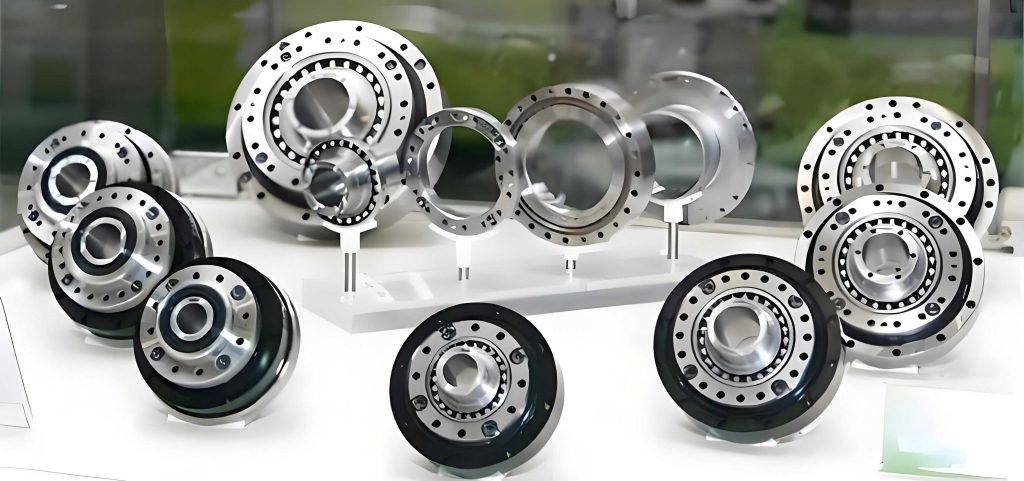
The rotary vector reducer features a two-stage reduction mechanism. The first stage consists of an involute cylindrical gear train, while the second stage employs a cycloidal pin-wheel planetary transmission. This combination allows for high reduction ratios in a compact form factor. The primary components include the central gear (input shaft), planetary gears, crank shafts, cycloidal gears, pin gear, and the planet carrier. The integration of these elements ensures smooth power transmission and load distribution. Understanding the structure is essential for optimization, as the dimensions of these parts directly influence the overall size and performance of the rotary vector reducer.
The working principle of the rotary vector reducer involves a sequential power flow. The input rotation from a servo motor is transmitted to the central gear, which meshes with multiple planetary gears to achieve the first-stage reduction. These planetary gears are connected to crank shafts via splines, transferring motion to the second stage. The crank shafts drive the cycloidal gears in an eccentric motion, causing them to rotate relative to the fixed pin gear. This interaction results in a reverse rotation of the cycloidal gears, which in turn drives the planet carrier to produce the output rotation. The overall transmission ratio is determined by the gear teeth numbers and the cycloidal geometry. This multi-stage process highlights the complexity of the rotary vector reducer and underscores the need for careful design to balance speed reduction, torque amplification, and physical constraints.
Designing a rotary vector reducer involves several stringent requirements to ensure reliability and performance in robotic applications. Key considerations include transmission efficiency, backlash, service life, compactness, and accuracy. Specifically, the efficiency should exceed 85% to minimize energy loss. Backlash must be controlled within tight limits to maintain precision in reversible motions. The reducer should have a sufficient lifespan under operational loads. Moreover, the volume or mass should be minimized without compromising other criteria, leveraging the high load-bearing capacity of the cycloidal stage. The transmission ratio error should not exceed 5% of the rated value, and the center distance of the cylindrical gear stage should be 50% to 60% of the pin gear center circle radius in the cycloidal stage. These requirements form the basis for our optimization model, guiding the selection of parameters for the rotary vector reducer.
To achieve an optimal design, we formulate a mathematical model with the objective of minimizing the volume of the rotary vector reducer. Since the volume is largely dictated by the gear dimensions, we focus on the center distance of the first-stage cylindrical gears as a proxy for overall size. The objective function is given by:
$$ a_0 = \frac{m(z_1 + z_2)}{2} $$
where \( m \) is the module, \( z_1 \) is the number of teeth on the central gear, and \( z_2 \) is the number of teeth on each planetary gear. These three variables are the primary design variables. Additional intermediate variables, such as the pin gear teeth number \( z_p \), are derived from constraints and system requirements.
The constraints for the optimization model are derived from mechanical design principles and operational needs. They ensure that the rotary vector reducer meets strength, efficiency, and dimensional criteria. Below, we list the key constraints with their mathematical expressions.
1. Bending Fatigue Strength for Cylindrical Gears: The module must satisfy the bending stress limit to prevent tooth failure:
$$ m \geq \sqrt[3]{\frac{2 K T_1 Y_{Fa} Y_{Sa}}{\phi_d z_1^2 [\sigma_F]}} $$
Here, \( K \) is the load factor, \( T_1 \) is the torque on the central gear, \( Y_{Fa} \) is the form factor, \( Y_{Sa} \) is the stress correction factor, \( \phi_d \) is the face width factor (taken as 0.3), and \( [\sigma_F] \) is the allowable bending stress. The torque \( T_1 \) is computed from the input power and speed:
$$ T_1 = \frac{9,550,000 P}{n i_1} $$
where \( P \) is the rated power, \( n \) is the rated output speed, and \( i_1 \) is the total transmission ratio of the rotary vector reducer, given by:
$$ i_1 = 1 + \frac{z_2 z_p}{z_1} $$
2. Contact Fatigue Strength for Cylindrical Gears: The gear teeth must also withstand contact stresses to avoid pitting:
$$ m z_1 \geq 2.32 \sqrt[3]{\frac{K T_1 (i_2 + 1) Z_E^2}{\phi_d i_2 [\sigma_H]^2}} $$
where \( Z_E \) is the elasticity coefficient (189.9 MPa\(^{1/2}\) for alloy steel), \( [\sigma_H] \) is the allowable contact stress, and \( i_2 \) is the first-stage transmission ratio:
$$ i_2 = \frac{z_2}{z_1} $$
3. Transmission Ratio Accuracy: The designed total ratio should closely match the rated value:
$$ \left| \frac{i_1 – i}{i_1} \right| \leq 0.01 $$
where \( i \) is the rated transmission ratio.
4. Gear Teeth Requirements: To prevent undercutting and ensure proper assembly, the central gear teeth number must be at least 18 and even (due to symmetric arrangement with multiple crank shafts). Also, to fully utilize the high torque capacity of the cycloidal stage, the first-stage ratio should not be too small:
$$ z_1 \geq 18, \quad i_2 \geq 1.5 $$
5. Dimensional Compatibility Between Stages: The center distance of the cylindrical gears should be 50% to 60% of the pin gear center circle radius in the cycloidal stage:
$$ 0.5 r_p \leq a_0 \leq 0.6 r_p $$
The pin gear center circle radius \( r_p \) is estimated from the output torque:
$$ r_p = (0.85 \sim 1.3) \sqrt[3]{T} $$
where \( T \) is the output torque, calculated as:
$$ T = \frac{9,550,000 i P \eta}{n} $$
Here, \( \eta \) is the overall efficiency of the rotary vector reducer, ranging from 0.85 to 1. It can be derived from the efficiencies of individual stages and bearings:
$$ \eta = \eta_{16} \eta_B = \frac{(i_6^H – 1)(i_6^H – \eta_6^H + i_1^H i_6^H \eta_1^H)}{(i_6^H – \eta_6^H)(i_6^H – 1 + i_1^H i_6^H)} \eta_B $$
with \( \eta_B = 0.993 \) for bearings, \( \eta_1^H = 0.992 \) for cylindrical gear meshing, \( \eta_6^H = 0.998 \) for cycloidal meshing, \( i_1^H = i_2 \), and \( i_6^H = z_p / (z_p – 1) \).
6. Material and Heat Treatment Specifications: The components of the rotary vector reducer require high hardness and wear resistance. Typical material selections and treatments are summarized in the table below to guide design choices and ensure durability.
| Component | Material | Heat Treatment | Precision Grade | Hardness (HRC) |
|---|---|---|---|---|
| Central Gear | 20Cr | Carburizing and Quenching | Grade 6 | 56–62 |
| Planetary Gear | 20Cr | Carburizing and Quenching | Grade 6 | 56–62 |
| Cycloidal Gear | GCr15 | Quenching | Grade 6 | 58–62 |
| Pin Gear | GCr15 | Quenching | Grade 5 | 58–62 |
These constraints collectively ensure that the optimized rotary vector reducer is both mechanically sound and dimensionally compact. The complexity of the model necessitates numerical methods for solution, which we implement using software tools.
To demonstrate the optimization process, we apply the model to a specific case: the RV-450E type rotary vector reducer. The design inputs are a rated power of 4.28 kW, a rated transmission ratio of 81, and a rated output speed of 5 r/min. We use MATLAB software to solve the optimization problem, leveraging its fmincon function for constrained nonlinear minimization. Due to the discrete nature of some variables (e.g., module must be from standard series, teeth numbers must be integers), we segment the program into three parts to handle these requirements sequentially. This approach improves computational accuracy and efficiency for the rotary vector reducer design.
The first part determines the module and gear parameters for the cylindrical stage. We iterate over standard module values while satisfying the strength constraints. The second part calculates the cycloidal stage parameters, such as pin gear teeth number and center radius, ensuring compatibility with the first stage. The third part integrates results to verify overall performance metrics. The optimization aims to minimize \( a_0 \), thereby reducing the volume of the rotary vector reducer. Below, we present the computed parameters and compare them with reference values from literature to validate our approach.
| Parameter | Optimized Value | Reference Value |
|---|---|---|
| Central gear teeth \( z_1 \) | 18 | 18 |
| Planetary gear teeth \( z_2 \) | 35 | 38 |
| Central gear width \( B_1 \) (mm) | 21 | 18 |
| Planetary gear width \( B_2 \) (mm) | 17 | 14 |
| Module \( m \) (mm) | 3 | 3 |
| Center distance \( a_0 \) (mm) | 79.5 | 84 |
| Pin gear teeth \( z_p \) | 42 | 38 |
| Cycloidal gear teeth \( z_c \) | 41 | 37 |
| Shortening factor \( K_1 \) | 0.8182 | 0.7355 |
| Pin gear center radius \( r_p \) (mm) | 154 | 155 |
| Pin gear radius \( r_{rp} \) (mm) | 8 | 8 |
| Cycloidal gear width \( b_c \) (mm) | 24 | 24 |
| Eccentricity \( a \) (mm) | 3 | 3 |
| Total transmission ratio \( i \) | 82.677 | 81.222 |
The results show close alignment between our optimized values and the reference data, confirming the accuracy of our model. Notably, the optimized center distance \( a_0 \) is smaller (79.5 mm vs. 84 mm), indicating a more compact design for the rotary vector reducer. This reduction in size aligns with our objective of volume minimization while maintaining all functional requirements. The slight deviations in teeth numbers and other parameters are within acceptable limits and reflect trade-offs in the optimization process. The overall transmission ratio error is minimal, satisfying the 1% constraint. This example underscores the effectiveness of our approach in enhancing the design of rotary vector reducers for practical applications.
Further analysis reveals that the optimization successfully balances the conflicting demands of strength, size, and efficiency. For instance, the selection of \( z_1 = 18 \) and \( z_2 = 35 \) meets the bending and contact stress constraints while keeping the center distance low. The cycloidal stage parameters, such as \( z_p = 42 \), ensure a high reduction ratio and smooth motion transmission. The use of MATLAB allowed for efficient handling of nonlinear constraints, though we had to adapt the algorithm to manage discrete variables. This experience highlights the importance of tailored computational strategies in designing complex systems like the rotary vector reducer.
In conclusion, we have presented a comprehensive optimization design methodology for the rotary vector reducer, focusing on volume minimization. By defining an objective function based on gear center distance and incorporating detailed constraints from mechanical and operational criteria, we developed a robust model. Applying this model to a real-world case using MATLAB software yielded parameters that are both accurate and improved in compactness compared to existing designs. This work demonstrates the value of optimization in advancing rotary vector reducer technology, contributing to more efficient and compact robotic drives. Future research could explore multi-objective optimization including weight and cost, or extend the model to dynamic performance considerations. Nonetheless, our approach provides a solid foundation for designing high-performance rotary vector reducers that meet the evolving needs of industrial automation.