
Traditional industrial robot end-effectors are typically designed for specific objects based on their shape and size. They generally can only perform predefined grasping tasks. Switching between different tasks often requires changing the end-effector, resulting in poor versatility and high cost. Their deployment requires re-programming and testing, preventing rapid adaptation to production lines and leading to inefficiency. Their adaptability is even worse in non-industrial scenarios. With the development of collaborative robots, the demand for safe, convenient, flexible, and intelligent grippers is growing daily. A dexterous robotic hand is an intelligent mechatronic system integrating multiple sensors, involving fields such as mechanics, electronics, and control. Currently, the few dexterous robotic hands available on the market still face issues such as complex structure, large size, insufficient grasping force, high cost, and difficult maintenance, limiting their use primarily to universities and research institutions. This article details the structural design of a three-fingered dexterous robotic hand featuring mechanical self-locking, underactuation, force sensing, and adaptability to objects of various shapes. Prototypes were built and tested, providing a reference for the development of intelligent dexterous hands.
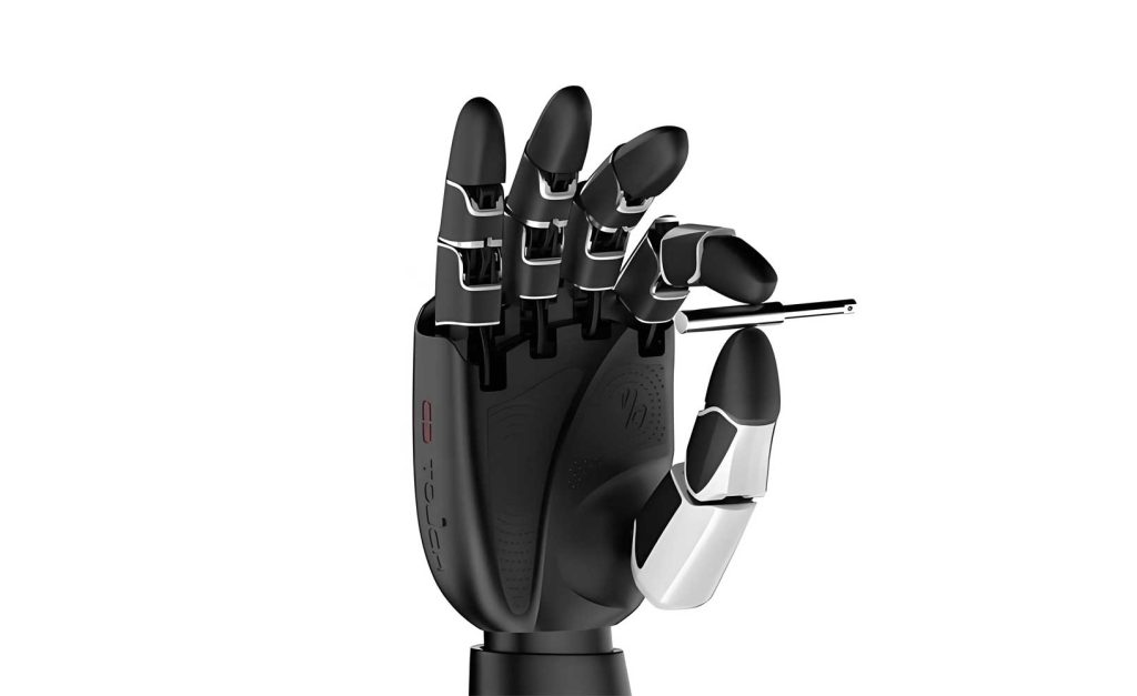
The core innovation of this dexterous robotic hand lies in its integrated electromechanical design. The goal was to create a compact, cost-effective, and highly functional dexterous robotic hand suitable for collaborative applications. The design philosophy centers on achieving sophisticated functionality—like adaptive grasping and force feedback—through relatively simple and robust mechanical principles, supplemented by integrated sensing and control.
1. Mechanical Design of the Finger and Underactuation
The finger mechanism is the fundamental unit of the dexterous robotic hand. Our design employs a single motor to drive two finger joints (proximal and distal), achieving a compact and lightweight structure. The power flow within a finger is as follows: The motor drives Gear I. Gear I meshes with Gear II, which is fixed to Gear III via pins, causing them to rotate together. Gear III meshes with both Gear IV and Gear V. Gear IV drives Worm I, which rotates Worm Wheel I. Worm Wheel I has an integrated cable pulley that drives the distal phalanx via a tendon (steel cable) transmission. Simultaneously, Gear V drives Worm II, which directly rotates the proximal phalanx (Worm Wheel II).
The underactuation feature allows the two joints to move sequentially using only one motor, enhancing adaptability. This is achieved through a unique mechanism connecting Gear V and Worm II. A threaded connection exists between the inner bore of Gear V and one end of Worm II. A set of disc springs applies an axial preload to this thread pair, creating sufficient friction for torque transmission under normal conditions. Thus, initially, both the proximal and distal phalanxes rotate simultaneously.
When the proximal phalanx contacts an object first, the resisting torque on Gear V increases. Once this torque exceeds the friction maintained by the disc spring preload, the thread pair slips: Gear V travels along the thread away from the springs, while Worm II stops. This halts the proximal phalanx. The distal phalanx, driven via the other transmission path (Gear IV, Worm I, and the tendon), continues to rotate until it also contacts the object or reaches its limit. The preload of the disc springs determines the slip torque threshold, making the underactuation sensitivity adjustable. During finger opening (motor reversal), the process reverses: Gear V travels back along the thread, initially allowing only the distal phalanx to move until the disc springs are compressed again, after which the proximal phalanx also returns to its initial position.
| Operating Phase | Gear V State | Worm II State | Proximal Phalanx | Distal Phalanx |
|---|---|---|---|---|
| Initial Closing (No Contact) | Rotating, thread locked | Rotating | Rotating | Rotating |
| Proximal Contact (Torque > Threshold) | Rotating & Translating | Stopped | Stopped | Rotating |
| Full Closure | Reached thread end | Stopped | Stopped | Stopped or in contact |
| Initial Opening | Reversing & Translating | Stopped | Stopped | Rotating (opening) |
| Final Opening | Rotating, thread locked | Rotating | Rotating (opening) | Rotating (opening) |
2. Integrated Force Sensing at the Fingertip
Force perception is crucial for a dexterous robotic hand to perform delicate and safe manipulation. Our design incorporates a moment sensor at the distal joint. The principle is based on measuring the tension difference in the tendon driving the distal phalanx. The tendon wraps around a pulley (D1) fixed to the distal joint. When the fingertip applies a moment T, the tension on one side of the tendon increases by ΔF, while the tension on the opposite side decreases by ΔF. An idler pulley, mounted on a flexible elastic element (cantilever beam), is placed between the two tendon strands. The net vertical force F_Y on the idler, resulting from the tension difference, causes a measurable bending strain in the elastic element.
Metal foil strain gauges attached to the elastic element convert this strain into a resistance change. A full Wheatstone bridge circuit with temperature compensation converts the resistance change into a stable voltage signal. The relationship between the applied fingertip moment and the generated strain is derived as follows:
The moment equilibrium at the distal joint pulley is:
$$ T = (F_0 + \Delta F) \cdot \frac{D_1}{2} – (F_0 – \Delta F) \cdot \frac{D_1}{2} = \Delta F \cdot D_1 $$
Therefore, $$ \Delta F = \frac{T}{D_1} $$
The vertical force on the idler (and thus the elastic element) is:
$$ F_Y = (F_0 + \Delta F)(\cos\alpha + \cos\beta) + (F_0 – \Delta F)(\cos\alpha + \cos\beta) $$
This simplifies to: $$ F_Y = 2\Delta F (\cos\alpha + \cos\beta) = \frac{2T (\cos\alpha + \cos\beta)}{D_1} $$
The strain ε at the location of the strain gauges (distance L from the idler center) is:
$$ \epsilon = \frac{F_Y \cdot L}{W \cdot E} = \frac{2T (\cos\alpha + \cos\beta) \cdot L}{D_1 \cdot W \cdot E} $$
where W is the section modulus of the elastic beam and E is its Young’s modulus.
The output voltage U_0 of the full bridge circuit is:
$$ U_0 = K \cdot \epsilon \cdot U $$
where K is the gauge factor and U is the excitation voltage.
Calibration is essential. The initial tendon tension F_0 must be greater than ΔF corresponding to the maximum designed moment T_max. If F_0 is too low, the slack-side tendon tension can drop to zero, causing a non-linear and unpredictable force-strain relationship. A dedicated calibration fixture with known weights is used to establish the precise relationship between moment and output signal. The tendon tension must be checked and adjusted periodically via a tensioning screw to maintain sensor accuracy.
3. Adaptive Grasping through Base Rotation
The three-fingered dexterous robotic hand configuration offers better force closure, stability, and operational flexibility compared to a two-fingered gripper. To further enhance adaptability to variously shaped objects, the two outer fingers (F1 and F3) can rotate synchronously in opposite directions relative to the fixed middle finger (F2). This is achieved by a dedicated “R-axis” module. A single motor drives a central worm, which turns two opposing worm wheels. Each worm wheel shaft has a pinion gear that engages with a larger gear connected to the finger base. This mechanism ensures symmetric, opposite rotation of the two outer fingers, creating different grasping postures (e.g., parallel, encompassing, or pinching). The worm gear drive provides a high reduction ratio and mechanical self-locking, ensuring the grasp is maintained even when power is off, increasing reliability and energy efficiency.
4. Position Control and Anti-Collision Algorithm
Each finger of the dexterous robotic hand is independently controlled, and the outer fingers have an additional rotational degree of freedom. This multi-DOF structure necessitates a strategy to prevent self-collision. Hall effect sensors paired with radially magnetized magnets measure the absolute rotation angle of the distal phalanx (via Worm Wheel I’s shaft) and the base rotation of the outer fingers (via the large base gear).
To implement anti-collision, the spatial coordinates of the three fingertips are calculated in real-time based on the measured joint angles. A simplified kinematic model for a finger is shown below. For the middle finger (F2), with its base fixed, the coordinates are:
$$ X_2 = 0 $$
$$ Y_2 = B\sin\theta_2 + C\sin(49^\circ + \frac{4}{3}\theta_2) $$
$$ Z_2 = -[A + B\cos\theta_2 + C\cos(49^\circ + \frac{4}{3}\theta_2)] $$
For an outer finger (e.g., F1), with a base rotation angle γ, the coordinates are:
$$ X_1 = D + [A + B\cos\theta_1 + C\cos(49^\circ + \frac{4}{3}\theta_1)] \sin\gamma $$
$$ Y_1 = B\sin\theta_1 + C\sin(49^\circ + \frac{4}{3}\theta_1) $$
$$ Z_1 = -[A + B\cos\theta_1 + C\cos(49^\circ + \frac{4}{3}\theta_1)] \cos\gamma $$
Where A, B, C, D are constant link lengths and offsets, and θ is the proximal joint angle (0° when fully extended). The distal joint angle is coupled as (49° + 4θ/3) based on the tendon routing ratio.
For simplicity in the initial implementation, a collision check is performed for the common case where all proximal joints have the same angle (θ1=θ2=θ3=θ). Under this condition, collision is avoided if specific geometric constraints regarding finger width ‘d’ and Z-coordinates are met. For more complex, asymmetric poses, a simulation in the host PC software is used to verify safe trajectories before execution.
5. Actuator Sizing and Selection
The dexterous robotic hand is designed for a maximum payload of 10 kg in an enveloping grasp. For a stable pinch grasp, the middle finger should provide twice the force of a side finger. Therefore, the single-finger active grasping force is sized for 2.5 kg. With a friction coefficient μ=0.5, the required normal fingertip force F is 50 N. With a typical contact point 15 mm from the joint axis, the required fingertip moment T_finger is:
$$ T_{finger} = F \times r = 50 \text{ N} \times 0.015 \text{ m} = 0.75 \text{ N·m} $$
The motor torque required to produce this fingertip moment is calculated by back-tracking through the transmission chain efficiencies (η) and reduction ratios (i).
| Transmission Stage | Reduction Ratio (i) | Efficiency (η) | Input Torque for Stage | Calculation |
|---|---|---|---|---|
| Fingertip Output | – | – | T_finger = 0.75 N·m | Design requirement |
| Tendon Pulley Input | i_tendon = 0.75* | 0.93 | T1 = 1.07 N·m | $$ T1 = \frac{T_{finger}}{i_{tendon} \cdot \eta} $$ |
| Worm Gear Input | i_worm = 50 | 0.37 | T2 = 0.058 N·m | $$ T2 = \frac{T1}{i_{worm} \cdot \eta} $$ |
| Gear Train Input | i_gear = 3.67 | 0.88 | T_motor_req = 0.0187 N·m | $$ T_{motor\_req} = \frac{T2}{i_{gear} \cdot \eta} $$ |
| *Note: The tendon ratio couples distal joint rotation to pulley rotation, resulting in an effective ratio less than 1. | ||||
A motor with a stall torque of 19 N·mm (0.019 N·m) was selected, satisfying the requirement. The grasping motion is transient, allowing the use of the motor’s peak capability. The opening/closing speed was verified based on the motor’s no-load speed and the total reduction ratio, resulting in a full open/close cycle time of approximately 0.72 seconds.
The R-axis motor was sized based on the worst-case static load: holding the two outer fingers horizontally. The torque required from the R-axis motor was calculated to be approximately 3.65 N·mm, leading to the selection of a 4.5 N·mm motor.
6. Hardware Architecture: Drive-Control Integration
To minimize the size and external wiring of the dexterous robotic hand, a custom drive-control integrated printed circuit board (PCB) was developed. An STM32F405 microcontroller serves as the core. The board’s key features include:
- One CAN interface for host computer communication.
- Four PWM outputs for motor speed control.
- One RS485 interface to read digital signals from the three fingertip force sensors.
- On-chip ADC channels to monitor motor currents for current-loop control.
- SPI interface to read absolute magnetic encoders for joint angles.
- Four hardware capture channels to read incremental encoders from the motors.
This single board implements current, velocity, and position control loops for all four motors (three fingers + one R-axis), as well as a high-level force/torque control loop, creating a truly integrated mechatronic system for the dexterous robotic hand.
7. Software Control and Intelligent Functions
The software leverages sensor data to implement advanced behaviors essential for a collaborative dexterous robotic hand. The core inputs are the joint angles from the Hall sensors and the fingertip moments from the strain gauge bridges.
Grasp Execution: The host sends commands for target position, grasping force, and speed. The controller moves the finger(s) until either the target position is reached or the target force is detected. Success/failure is determined by comparing final state to command.
Anti-Slip/Re-Grasp: When enabled, the software continuously monitors the fingertip moments after a successful grasp. If a significant drop in force is detected (indicating slip), the controller automatically initiates a re-grasping sequence with increased force. A status signal indicates whether the object was recovered or lost.
Drop Detection: If the anti-slip function is disabled and all three fingertip forces suddenly fall to zero, the software triggers a “drop detected” event.
Human-Robot Collaboration (HRC): When the HRC safety mode is enabled, the software monitors for an unexpected external force applied to the fingers. If a sustained force increase is detected (indicating human contact or collision), the controller immediately commands the dexterous robotic hand to open and retract to a home position, ensuring human safety.
8. Prototype Verification and Performance
Two successive prototypes of the intelligent three-fingered dexterous robotic hand were built and tested. The key functional validations included:
- Underactuation: Successful sequential grasping of objects that contact the proximal phalanx first, confirming the designed slip-clutch mechanism works as intended.
- Force Sensing: The calibrated fingertip sensors provided repeatable and linear measurements up to the designed 1.5 N·m moment, enabling force-controlled grasps.
- Adaptive Grasping: The R-axis allowed the hand to reconfigure between parallel, encompassing, and pinch grasps, reliably holding objects of diverse shapes (cylinders, spheres, cubes).
- Self-Locking: The worm gear mechanisms successfully maintained grip without power consumption, a critical feature for safety and energy efficiency.
- Integrated Control: All motors, sensors, and communication functions operated correctly via the custom drive-control board, demonstrating the viability of the highly integrated architecture.
9. Conclusion
The design and development of this intelligent three-fingered dexterous robotic hand demonstrate a practical approach to creating a versatile, sensor-rich, and cost-effective manipulator. By combining underactuated mechanics for adaptability, integrated strain-gauge-based force sensing for tactile feedback, and a self-locking base rotation for posture change, the hand achieves significant functionality. The use of a custom驱控一体 (drive-control-integrated) board drastically reduces size and complexity. The implemented software algorithms provide essential intelligent behaviors like anti-slip control and human-collaborative safety features. This dexterous robotic hand platform is well-suited for integration with collaborative robots for applications in flexible manufacturing, logistics, healthcare, and service domains. Future work will focus on refining the anti-collision algorithms for fully arbitrary poses, improving the power-to-weight ratio, and developing higher-level manipulation primitives using the rich sensor data. The continued convergence of advanced mechanics, embedded computing, and intelligent control will push dexterous robotic hands closer to the versatility and sensitivity of the human hand.