
The pursuit of advanced robotic manipulation has driven significant research into multi-fingered end-effectors, commonly known as **dexterous robotic hands**. Unlike traditional grippers designed for singular, repetitive tasks, a true **dexterous robotic hand** aims to replicate the versatility and adaptability of the human hand. This capability is crucial for operations in unstructured or hazardous environments, such as space, nuclear facilities, or disaster response scenarios, where robots must interact with a diverse array of objects and tools. The core challenge lies in achieving not only complex motion but also stable and force-closure grasps on objects of varying geometry and weight. This article presents a comprehensive study on the design, static analysis, grasp modeling, and dynamic simulation of a three-fingered **dexterous robotic hand**. We detail the mechanical architecture inspired by human finger kinematics, perform a rigorous static analysis using the Jacobian matrix, formulate an envelope grasp model for cylindrical objects, and validate the hand’s performance through dynamic simulation in Adams software, providing a foundation for future precise motion control algorithms.
Mechanical Architecture of the Dexterous Robotic Hand
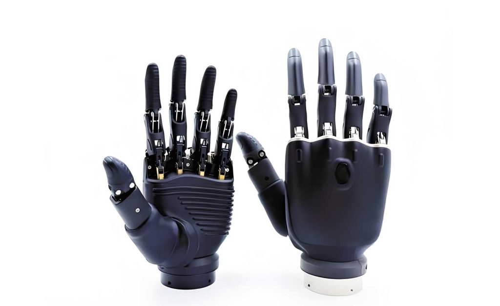
The design philosophy for our **dexterous robotic hand** prioritizes biomimicry and functional versatility. Observing that the human index, middle, ring, and little fingers each possess three primary joints, we adopted a uniform three-joint, three-phalange structure for each finger in our design. This configuration provides sufficient degrees of freedom for both dexterous, precision manipulation and robust, enveloping grasps. The hand assembly consists of three identical fingers, a rigid palm, and a 360-degree rotatable wrist, offering additional orienting capability. Each finger is fully actuated by individual electric motors, a common and effective approach in modern **dexterous robotic hand** designs like the Shadow Dexterous Hand and others, allowing for independent control of each joint. The kinematic parameters for a single finger are summarized in Table 1.
| Phalanx Name | Length (mm) | Range of Motion (deg) | Actuation Method |
|---|---|---|---|
| Distal Phalanx (Fingertip) | 35 | 0 – 90 | Electric Motor |
| Middle Phalanx | 45 | 0 – 90 | Electric Motor |
| Proximal Phalanx | 60 | 0 – 90 | Electric Motor |
The three-dimensional model of the assembled **dexterous robotic hand** illustrates a compact and mechanically feasible design. This configuration enables the hand to execute various grasp types, from precision pinches to power enveloping grasps, which will be analyzed in subsequent sections.
Static Analysis Using the Jacobian Matrix
Static analysis is fundamental for understanding the force transmission within a **dexterous robotic hand** during a stable grasp. It establishes the relationship between the contact forces applied at the fingertips (or phalanges) and the torques required at the joint actuators to maintain equilibrium. The primary tool for this analysis is the Jacobian matrix, which encapsulates the geometric relationship between joint space velocities and Cartesian end-effector velocities.
For a finger with joint variables denoted by the vector $\mathbf{Q} = [q_1, q_2, …, q_n]^T$ and its end-effector pose (position and orientation) in the base frame as $\mathbf{P} = [x_t, y_t, z_t, \theta_x, \theta_y, \theta_z]^T$, the forward kinematics is given by $\mathbf{P} = \Phi(q_1, q_2, …, q_n)$. Differentiating with respect to time yields the velocity relationship:
$$ \dot{\mathbf{P}} = \mathbf{J}(\mathbf{Q}) \dot{\mathbf{Q}} $$
where $\mathbf{J}(\mathbf{Q})$ is the geometric Jacobian matrix. For an $n$-degree-of-freedom finger, $\mathbf{J}$ is a $6 \times n$ matrix that can be partitioned into linear and angular velocity components:
$$ \mathbf{J} = \begin{bmatrix}
\mathbf{J}_{L1}\dot{q}_1 + \mathbf{J}_{L2}\dot{q}_2 + … + \mathbf{J}_{Ln}\dot{q}_n \\
\mathbf{J}_{A1}\dot{q}_1 + \mathbf{J}_{A2}\dot{q}_2 + … + \mathbf{J}_{An}\dot{q}_n
\end{bmatrix} $$
Here, $\mathbf{J}_{Li}$ and $\mathbf{J}_{Ai}$ represent the linear and angular velocity contribution coefficients of the $i$-th joint, respectively. For our planar three-link finger model (considering motion in the X-Y plane for analysis simplicity), with link lengths $l_1, l_2, l_3$ and joint angles $\theta_1, \theta_2, \theta_3$, the Jacobian matrix relating the fingertip linear velocity to the joint velocities is derived as:
$$ \mathbf{J} = \begin{bmatrix}
-l_1 s_1 – l_2 s_{12} – l_3 s_{123} & -l_2 s_{12} – l_3 s_{123} & -l_3 s_{123} \\
l_1 c_1 + l_2 c_{12} + l_3 c_{123} & l_2 c_{12} + l_3 c_{123} & l_3 c_{123}
\end{bmatrix} $$
where $s_1 = \sin\theta_1$, $c_{12} = \cos(\theta_1+\theta_2)$, $s_{123} = \sin(\theta_1+\theta_2+\theta_3)$, and so on.
The principle of virtual work allows us to extend this kinematic relationship to statics. In a static equilibrium condition, the virtual work done by the joint torques $\boldsymbol{\tau}$ must equal the virtual work done by the external force $\mathbf{F}$ applied at the end-effector (or contact point):
$$ \delta W = \mathbf{F}^T \delta \mathbf{x} = \boldsymbol{\tau}^T \delta \mathbf{Q} $$
Since $\delta \mathbf{x} = \mathbf{J} \delta \mathbf{Q}$, we have:
$$ \boldsymbol{\tau}^T \delta \mathbf{Q} = \mathbf{F}^T \mathbf{J} \delta \mathbf{Q} $$
This holds for all virtual displacements $\delta \mathbf{Q}$, leading to the fundamental static force transformation for a **dexterous robotic hand** finger:
$$ \boldsymbol{\tau} = \mathbf{J}^T(\mathbf{Q}) \mathbf{F} $$
This equation is pivotal. It allows us to compute the required joint torques $\boldsymbol{\tau}$ to produce a desired set of contact forces $\mathbf{F}$ at the fingertip, or conversely, to determine the contact forces generated by a given set of joint torques. This forms the bedrock for grasp force optimization and control in a multi-fingered **dexterous robotic hand** system.
Grasp Modeling for Enveloping Cylindrical Objects
Grasp modeling aims to define the conditions under which a **dexterous robotic hand** can securely hold an object. We focus on power or enveloping grasps, where multiple phalanges of each finger make contact with the object surface, providing stability and the ability to resist external wrenches. A cylindrical object is chosen as a canonical example due to its prevalence in industrial settings.
We consider a two-dimensional cross-section of the grasp, where the thumb opposes the combined force of the index and middle fingers. The palm also provides a supporting contact. The geometric condition for enveloping is that each contacting phalanx must be tangent to the object’s circular cross-section. This condition establishes a set of nonlinear relationships between the object’s center position $(x_0, y_0)$, its radius $r$, the contact point coordinates $(x_i, y_i)$, and the finger joint angles $\theta_i$.
For instance, considering the thumb’s proximal phalanx contact point $A(x_1, y_1)$ and its joint angle $\theta_1$, the $y$-coordinate is $y_1 = -x_1 \tan\theta_1$. The object center coordinates are then:
$$ x_0 = x_1 + r \sin\theta_1, \quad y_0 = y_1 – r \cos\theta_1 $$
The distance from the thumb’s metacarpophalangeal (MCP) joint to the contact point $B$ on the middle phalanx, denoted $L_B$, can be derived from the tangent condition as:
$$ L_B = \sqrt{ (x_1 + l_1 \cos\theta_1)^2 + (y_1 – l_1 \sin\theta_1)^2 – r^2 } $$
where $l_1$ is the length of the proximal link. Similar geometric constraints apply to all other contact points on the index and middle fingers. In our specific **dexterous robotic hand** design, the distal and middle joints are coupled (i.e., $\theta_3 = \theta_2$ for the thumb, $\theta_6 = \theta_5$ for the opposing fingers), which simplifies the kinematics but adds a design constraint to the grasp posture.
The force balance condition ensures the grasped object is in static equilibrium. Isolating the object as a free body, the vector sum of all contact forces (from the thumb, fingers, and palm) must be zero, and the net moment about the object center must also be zero. For the planar case, this yields two force equilibrium equations:
$$ \sum F_x: \quad F_3 s_{123} + F_2 s_{12} + F_1 s_1 – F_5 s_{456} – F_4 s_{45} = 0 $$
$$ \sum F_y: \quad F_3 c_{123} + F_2 c_{12} + F_5 c_{456} – F_1 c_1 – F_4 c_{45} – F_0 = 0 $$
Here, $F_i$ represents the normal contact force at the $i$-th contact point (numbered sequentially from thumb to fingers), $F_0$ is the palm contact force, and $s_{ijk} = \sin(\theta_i+\theta_j+\theta_k)$. Simultaneously, the static equilibrium of each finger link, governed by $\boldsymbol{\tau} = \mathbf{J}^T \mathbf{F}$ for that specific contact geometry, provides the relationship between these contact forces and the joint driving torques $\tau_j$. For the thumb, the torque equations at the proximal and medial joints are:
$$ \tau_1 = F_1 L_A + F_2 (L_B + l_1 c_2) + F_3 (L_C + l_1 c_{23} + l_2 c_3) $$
$$ \tau_2 = F_2 L_B + F_3 (L_C + l_2 c_3) $$
where $L_A, L_B, L_C$ are moment arms from the joint centers to their respective contact points. Solving this combined system of geometric constraint equations and force/torque balance equations allows for the analysis and planning of stable enveloping grasps with this **dexterous robotic hand** architecture.
Dynamic Simulation of Power Grasping
To validate the design and analyze its dynamic performance, a virtual prototype of the **dexterous robotic hand** was created and simulated using Adams multi-body dynamics software. The model was imported from a detailed CAD assembly. Appropriate constraints (revolute joints at each finger joint, a fixed palm), material properties, and contact parameters (stiffness, damping, friction) between the finger phalanges and a cylindrical object were defined. The grasp sequence was programmed by applying motor-driven motion functions to the joints: initially, the proximal joints close until contact, followed by the medial and then the distal joints, mimicking a natural enveloping action.
The simulation successfully demonstrated the hand’s capability for both power grasps on larger cylinders and precision grasp modes on smaller objects, confirming the structural rationality and flexibility of the design. The dynamic simulation of the power grasp provides crucial data unreachable by static analysis alone: the transient evolution of contact forces during the grasping process.
Due to the asymmetric arrangement, the thumb and the opposing fingers (index/middle) experience different force histories, though the index and middle fingers exhibit similar patterns. The contact force profiles on the Y-axis (primary direction opposing gravity) for each phalanx reveal the sequence and stability of the grasp, as summarized in Table 2.
| Finger & Phalanx | Contact Time (s) | Force Profile Characteristics | Steady-State Behavior |
|---|---|---|---|
| Thumb – Proximal | ~0.2 | Sharp peak and significant initial vibration upon impact. | Force stabilizes quickly as other joints engage, damping the initial disturbance. |
| Thumb – Medial | ~0.5 | Rapid rise to a peak followed by a decline. | Stabilizes to a steady value; the initial peak helps suppress vibration from the proximal joint contact. |
| Thumb – Distal | ~0.8 | Smooth increase to final value. | Reaches stable contact force rapidly, as the system is already pre-stabilized by the two preceding joints. |
| Index/Middle – Proximal | ~0.2 | Similar sharp peak and vibration as thumb proximal joint. | Stabilizes after engagement of subsequent joints. |
| Index/Middle – Medial | ~0.5 | Rapid peak and decline profile. | Converges to a stable force, contributing to system damping. |
| Index/Middle – Distal | ~0.8 | Smooth increase. | Reaches stable equilibrium force smoothly. |
The simulation results clearly show a phased and stable force progression. The initial impacts at the proximal joints cause transient vibrations, which are effectively damped out by the subsequent contact events of the medial and distal phalanges. By the time the distal phalanges make contact, the entire **dexterous robotic hand**-object system is nearing a state of equilibrium, resulting in smooth force application from these final contact points. This demonstrates the inherent stability of the sequential, multi-point contact strategy employed by the **dexterous robotic hand** for power grasps.
Conclusion
This study has presented a holistic investigation into the development of a three-fingered **dexterous robotic hand**. We detailed a biomimetic mechanical design featuring three fully motor-driven joints per finger, enabling both dexterous and powerful grasps. A fundamental static analysis was conducted using the Jacobian matrix, deriving the critical relationship $\boldsymbol{\tau} = \mathbf{J}^T \mathbf{F}$ that links joint actuation to endpoint contact forces. Furthermore, a detailed geometric and force-balance model for enveloping grasps on cylindrical objects was formulated, capturing the interdependence of posture, contact points, and forces within the **dexterous robotic hand** system.
Dynamic simulation in Adams software validated the design’s functionality, visually confirming its ability to perform various grasp types. More importantly, the simulation provided a detailed temporal analysis of contact forces during a power grasping sequence. The results illustrated a stable, phased force build-up where initial transient vibrations are effectively suppressed by the sequential engagement of multiple phalanges, leading to a robust final equilibrium. This analysis confirms the structural soundness and grasp stability of the proposed **dexterous robotic hand** architecture. The models and findings established here—encompassing kinematics, statics, grasp geometry, and dynamic performance—form a essential foundation for the next critical phase: the implementation of advanced, precise motion and force control algorithms to fully exploit the capabilities of this **dexterous robotic hand** in complex manipulation tasks.