
The development of biomimetic, dexterous robotic hands characterized by low cost, high flexibility, and light weight remains a prominent focus within the field of intelligent robotics. Such hands, mirroring the human hand’s morphology and motor capabilities, are essential for versatile grasping and manipulation tasks. They serve not only as critical end-effectors for service robots but also hold significant potential for advanced prosthetic applications. Robotic hands are typically categorized into fully-actuated and underactuated types based on their actuation schemes. While fully-actuated hands offer independent joint control, they often suffer from complexity, large size, high weight, and substantial cost. Underactuated dexterous robotic hands, utilizing fewer actuators than degrees of freedom (DoFs), present a compelling alternative by promising lighter weight, more compact designs, simpler control, and reduced cost. However, conventional underactuation introduces coupled motion between joints, limiting the ability to control each joint’s posture independently and thus restricting dexterity.
To address the challenge of achieving lightweight, compact design without sacrificing the controllability of individual joints in an underactuated system, this work presents the design and validation of a novel five-finger dexterous robotic hand. The core innovation lies in integrating electromagnetic technology with principles from metamorphic mechanisms to impose selective constraints on the finger joints. This approach enables individual control over each joint’s freedom even within an underactuated tendon-driven framework, effectively decoupling their motions when required. The following sections detail the mechanical design, kinematic analysis, modeling and simulation of the joint constraint mechanism, and experimental validation through various grasping tasks. The results demonstrate that this dexterous robotic hand achieves a remarkable combination of adaptive enveloping grasps and stable, precise pinches, offering a new pathway toward compact and versatile end-effectors for applications such as robotic caregiving.
Structural Design of the Dexterous Robotic Hand
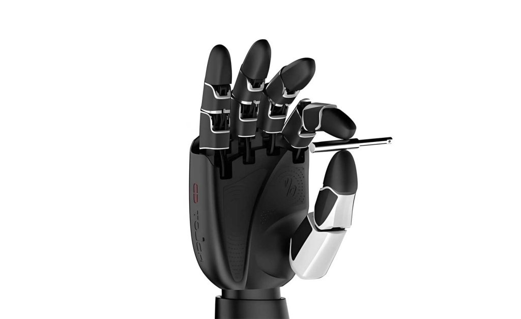
The dexterous robotic hand is designed with a modular philosophy, drawing inspiration from the anatomical proportions and functional arrangement of the human hand. The overall design aims for a balance between anthropomorphism, functionality, and mechanical simplicity.
Overall Architecture and Kinematic Configuration
The hand possesses a total of 15 degrees of freedom (DoFs). The index, middle, ring, and little fingers each have 3 DoFs, corresponding to the metacarpophalangeal (MCP), proximal interphalangeal (PIP), and distal interphalangeal (DIP) joints. The axes of these joints are arranged in parallel. The thumb also has 3 DoFs, comprising a carpometacarpal (CMC) joint, a MCP joint, and an interphalangeal (IP) joint. The axis of the CMC joint is oriented perpendicularly to the axes of the subsequent thumb joints, providing opposition capability.
A key aspect of the anthropomorphic design is the arrangement of the little finger. Observing human grasping postures, particularly for spherical objects with a radius of approximately 50 mm, the little finger naturally aligns at an angle relative to the middle finger. To replicate this functional geometry and enhance coordination between the thumb and little finger during power grasps, the little finger is mounted with its MCP joint axis approximately 25° from that of the middle finger and parallel to the thumb’s CMC joint axis. This arrangement promotes a more natural and stable enclosing grasp.
The actuation system employs a single motor and a single tendon per finger, resulting in a total of five motors for the entire dexterous robotic hand. This underactuated scheme significantly reduces the complexity and bulk of the driving system located in the palm or forearm. Force sensors are integrated into the fingertip and palmar pad of each phalanx to detect contact states. Additionally, dorsal holes on each phalanx accommodate elastic elements (e.g., extension springs) to provide the restoring force necessary for finger extension when the tendon is released.
Tendon Pre-Tensioning Mechanism
In tendon-driven systems, prolonged cyclic operation can lead to tendon elongation or slackness, causing backlash and reducing transmission efficiency and positional accuracy. To mitigate this issue and ensure long-term reliability, an integrated pre-tensioning mechanism is designed into the palmar side of the inter-phalangeal connections.
The mechanism consists of a pre-tension guide block, a pre-tension adjustment block, and a set screw. The guide block is fixed and defines the routing path. The adjustment block features two arcuate slots, providing different routing paths to accommodate variations in effective tendon length. By loosening the set screw, the adjustment block can be slid along the slots, taking up any slack in the tendon. Tightening the screw then locks the adjustment block in place, maintaining the required tendon tension. This design allows for easy, post-assembly tension adjustment and periodic re-tensioning throughout the lifespan of the dexterous robotic hand, ensuring consistent and precise actuation.
Electromagnetically-Locked Rotational Joint
The heart of the novel joint constraint system is the electromagnetically-locked rotational joint. This mechanism allows any finger joint to be selectively locked or freed, transforming the kinematic chain of the underactuated finger.
The main components include a locking gear, a rotating shaft, an armature (plunger), a compression spring, and an electromagnet. The locking gear is fixed to the rotating shaft. The armature is attached to the shaft within an internal slot. The spring is seated in an external annular groove on the shaft. The electromagnet is fixed to the housing of the subsequent phalanx (Joint Connection Plate II). The assembled shaft-spring-armature sub-assembly is then fitted over the electromagnet.
In the default state (electromagnet off), the spring force pushes the shaft assembly away from the electromagnet. This disengages the locking gear from an internal gear ring mounted on the preceding phalanx (Joint Connection Plate I), allowing the joint to rotate freely.
When the electromagnet is energized, it generates a magnetic force that attracts the armature, overcoming the spring force. This causes the entire shaft assembly to translate axially, meshing the locking gear with the internal gear ring. This engagement completely locks the joint, removing its rotational degree of freedom. By controlling the on/off state of the electromagnet at each joint, individual joint motions can be constrained. For instance, locking the DIP joint effectively turns the middle and distal phalanges into a single rigid link. Locking both the PIP and DIP joints turns the entire finger into a single rigid body. This capability allows the underactuated dexterous robotic hand to achieve specific finger postures and precise fingertip positioning that are typically unattainable with conventional underactuated coupling, effectively emulating the joint-level control of a fully-actuated hand.
Kinematic Analysis and Workspace of the Dexterous Robotic Hand
Given the modular and symmetric design of the fingers, kinematic analysis is performed on the index finger as a representative model. The Denavit-Hartenberg (D-H) convention is employed to establish the coordinate frames and derive the forward kinematics.
Forward Kinematics Model
The coordinate frames are assigned as shown in the model, with Frame {0} at the MCP joint base and Frame {3} at the fingertip. The D-H parameters for the index finger are summarized in the table below.
| Link i | $\theta_i$ (Joint Variable) | $d_i$ (mm) | $a_i$ (Link Length, mm) | $\alpha_i$ (°) |
|---|---|---|---|---|
| 1 (Proximal) | $\theta_1$ (0~90°) | 0 | $l_1=30$ | 0 |
| 2 (Middle) | $\theta_2$ (0~96°) | 0 | $l_2=30$ | 0 |
| 3 (Distal) | $\theta_3$ (0~99°) | 0 | $l_3=23$ | 0 |
The homogeneous transformation matrix for link i is given by:
$$A_i = \begin{bmatrix}
\cos\theta_i & -\sin\theta_i\cos\alpha_i & \sin\theta_i\sin\alpha_i & a_i\cos\theta_i \\
\sin\theta_i & \cos\theta_i\cos\alpha_i & -\cos\theta_i\sin\alpha_i & a_i\sin\theta_i \\
0 & \sin\alpha_i & \cos\alpha_i & d_i \\
0 & 0 & 0 & 1
\end{bmatrix}$$
Given $\alpha_i = 0$, the matrices simplify to:
$$A_1 = \begin{bmatrix}
\cos\theta_1 & -\sin\theta_1 & 0 & l_1\cos\theta_1 \\
\sin\theta_1 & \cos\theta_1 & 0 & l_1\sin\theta_1 \\
0 & 0 & 1 & 0 \\
0 & 0 & 0 & 1
\end{bmatrix}, \quad A_2 = \begin{bmatrix}
\cos\theta_2 & -\sin\theta_2 & 0 & l_2\cos\theta_2 \\
\sin\theta_2 & \cos\theta_2 & 0 & l_2\sin\theta_2 \\
0 & 0 & 1 & 0 \\
0 & 0 & 0 & 1
\end{bmatrix}, \quad A_3 = \begin{bmatrix}
\cos\theta_3 & -\sin\theta_3 & 0 & l_3\cos\theta_3 \\
\sin\theta_3 & \cos\theta_3 & 0 & l_3\sin\theta_3 \\
0 & 0 & 1 & 0 \\
0 & 0 & 0 & 1
\end{bmatrix}$$
The overall transformation from the base frame {0} to the fingertip frame {3} is:
$$^0_3T = A_1 A_2 A_3 = \begin{bmatrix}
\cos\Theta & -\sin\Theta & 0 & l_1\cos\theta_1 + l_2\cos(\theta_1+\theta_2) + l_3\cos\Theta \\
\sin\Theta & \cos\Theta & 0 & l_1\sin\theta_1 + l_2\sin(\theta_1+\theta_2) + l_3\sin\Theta \\
0 & 0 & 1 & 0 \\
0 & 0 & 0 & 1
\end{bmatrix}$$
where $\Theta = \theta_1 + \theta_2 + \theta_3$.
The position of the fingertip in the base frame is given by the last column of $^0_3T$:
$$^0\mathbf{p}_3 = \begin{bmatrix} x \\ y \\ z \end{bmatrix} = \begin{bmatrix} l_1\cos\theta_1 + l_2\cos(\theta_1+\theta_2) + l_3\cos(\theta_1+\theta_2+\theta_3) \\
l_1\sin\theta_1 + l_2\sin(\theta_1+\theta_2) + l_3\sin(\theta_1+\theta_2+\theta_3) \\
0 \end{bmatrix}$$
Workspace Analysis
The reachable workspace of the index fingertip is analyzed using the Monte Carlo method, randomly sampling joint angles within their physiological limits ($\theta_1 \in [0, \pi/2]$, $\theta_2 \in [0, 96\pi/180]$, $\theta_3 \in [0, 99\pi/180]$). The resulting point cloud, representing all possible fingertip positions, defines the workspace.
The analysis reveals a workspace that extends approximately 83 mm in the positive x-direction (forward from the knuckle) and spans from -53 mm to +83 mm in the y-direction (perpendicular to the finger’s initial orientation). In a standard underactuated finger with coupled joints, the fingertip trajectory is constrained to a specific path within this potential workspace, often unable to reach its boundaries. However, the joint constraint mechanism in this dexterous robotic hand enables the fingertip to access the extreme points of this workspace. By locking specific joints, the finger’s kinematic structure changes (e.g., from a three-link to a two-link or one-link system), allowing the actuator to position the fingertip directly at workspace boundaries that correspond to those constrained configurations. This significantly enhances the dexterity and positioning capability of the underactuated finger.
Modeling and Analysis of the Joint Constraint Mechanism
The reliable operation of the electromagnetic joint lock is critical for the functionality of the dexterous robotic hand. A simplified dynamic model is established to analyze the forces involved, and finite element simulation is used to size the electromagnet and select an appropriate air gap.
Dynamic Model of the Locking Action
The motion of the armature-shaft assembly during locking and unlocking can be modeled by considering the primary forces at play: the electromagnetic force ($F_c$), the spring force ($F_s$), and a damping force ($C$) accounting for friction and other losses. Let $z$ be the air gap between the armature and the electromagnet core, and $k$ be the spring stiffness.
The spring force, including preload $F_0$, is:
$$F_s = k x + F_0$$
where $x$ is the spring compression.
The electromagnetic force is a function of the current $I$ and the air gap $z$:
$$F_c = \frac{I^2}{2} \frac{dL(z)}{dz}$$
where $L(z)$ is the inductance as a function of gap.
For successful engagement (electromagnet on), the net force must be positive:
$$F_c – F_s – C > 0$$
For reliable disengagement (electromagnet off), the spring must overcome damping:
$$F_s – C > 0$$
Parameter Selection and Electromagnetic Simulation
Based on mechanical design constraints, a P10-10 cup-type electromagnet is selected. Key parameters are listed below.
| Model | Rated Voltage | Height | Base Diameter | Rated Holding Force |
|---|---|---|---|---|
| P10-10 | 24 V DC | 10 mm | 10 mm | 5 N |
A compression spring is chosen with the following properties: wire diameter $d=0.8$ mm, mean coil diameter $D=14$ mm, active coils $n=3$, and free length $H=7$ mm. The spring stiffness $k$ is calculated using the formula for cylindrical helical springs:
$$k = \frac{G d^4}{8 D^3 n}$$
where $G$ is the shear modulus of the material (e.g., carbon steel).
Preliminary tests indicated that a minimum electromagnetic force ($F_{min}$) of approximately 1.5 N is required to reliably lock the joint against expected loads and spring forces. To ensure robust operation, a safety factor $s \ge 2$ is targeted for the design electromagnetic force. ANSYS Electronics software is used to simulate the magnetic field and force for different air gaps ($z$) ranging from 0 to 2 mm.
The simulation results show that the electromagnetic force decreases non-linearly with increasing air gap, from a maximum near 6 N (at ideal contact, $z=0$) to about 2.8 N at $z=2$ mm. The force drop is most rapid for gaps between 0 and 0.5 mm. For gaps between 0.5 mm and 1.5 mm, the force decline is more gradual and approximately linear, which is desirable for stable and predictable actuation.
Considering the required $F_{min}$, the desired safety factor, and the need to accommodate manufacturing tolerances and ensure easy assembly, an air gap of $z = 1$ mm is selected. At this gap, the simulated electromagnetic force significantly exceeds $F_{min}$ with an adequate safety margin. The finite element analysis at this gap confirms a well-defined magnetic flux path through the core and armature, with the air gap presenting the expected region of high magnetic reluctance.
Grasping Experiments and Functional Validation
A prototype of the dexterous robotic hand was fabricated using photosensitive resin for the links and housing. Experiments were conducted to validate the hand’s fundamental capabilities in both power (enveloping) and precision (pinch) grasping, which are essential for a versatile end-effector.
Enveloping Grasp
In this mode, all five fingers are actuated simultaneously via their respective tendons without activating any joint locks. The fingers curl inwards under tendon tension, conforming to the object’s shape through their passive compliance and the underactuated coupling. Grasping concludes when the tendons can no longer be pulled, indicating that the object is fully enveloped and contact forces have been established. The prototype successfully performed stable enveloping grasps on objects like a cylindrical cup and a rubber ball. The adaptive nature of the underactuated fingers, combined with the anthropomorphic palm and finger spacing, allowed the dexterous robotic hand to securely hold these objects of different shapes and sizes.
Precision Grasp
Precision grasping requires the fingers to assume specific, often static, postures to grip an object between the fingertips. This is where the joint constraint mechanism is crucial. For a two-finger pinch (e.g., thumb and index finger), the electromagnets in the MCP and PIP joints of the index finger and the MCP joint of the thumb were energized, locking these joints. The hand was then actuated, causing motion only at the unlocked joints (the thumb IP and the index DIP in this configuration) until the fingertips made contact with a small object, such as a medicine bottle. Similarly, for a three-finger precision grasp, additional joints on the middle finger were locked to achieve a stable tripod pinch on an object like an eye-drop container.
The experiments confirmed that the dexterous robotic hand could reliably switch between grasping modes. The electromagnetic locks engaged and disengaged consistently, enabling the transition from a fully adaptive, underactuated state to a configuration with selectively rigid joints for precise manipulation. This dual-mode capability highlights the unique advantage of this design: it retains the simplicity, adaptability, and robustness of an underactuated hand while gaining the posture-specific control typically reserved for fully-actuated systems.
Conclusion
This work presented the design, analysis, and validation of a novel underactuated five-finger dexterous robotic hand that incorporates an active joint constraint system. By fusing principles from underactuated tendon-drive, metamorphic mechanisms, and electromagnetic actuation, the hand achieves independent control over individual joint freedoms despite having fewer actuators than degrees of freedom. The modular finger design with an integrated tendon pre-tensioner ensures maintainability and consistent performance. Kinematic analysis defined the finger’s workspace, which can be fully exploited thanks to the joint-locking capability. Electromagnetic simulation validated the design of the constraint mechanism, ensuring reliable operation. Finally, prototype experiments demonstrated successful enveloping and precision grasps on various objects.
The developed dexterous robotic hand offers a compelling solution that bridges the gap between the mechanical simplicity and compactness of underactuated hands and the precise controllability of fully-actuated hands. This makes it a particularly attractive candidate for applications where size, weight, cost, and versatility are critical, such as in next-generation service and assistive robots. The design provides a new and effective approach to creating capable, dexterous robotic hands for complex interactive tasks.