
In recent years, with evolving dietary habits and lifestyle changes, the prevalence of cerebrovascular diseases has risen significantly, particularly stroke. Stroke is characterized by high incidence, mortality, and disability rates, often resulting in severe motor impairments. Among these, hand motor dysfunction poses a substantial challenge to daily living, placing a heavy burden on individuals and families. To address this, various hand rehabilitation devices have been developed, with the flexible multi-fingered dexterous robotic hand emerging as a key technology. This dexterous robotic hand mimics the human hand’s flexibility and grasping capabilities, assisting patients in performing flexion, extension, and grasping motions, thereby enhancing rehabilitation outcomes. The application of such dexterous robotic hands in medical rehabilitation, including surgical assistance, functional recovery, and nursing care, has garnered widespread attention. As research advances, optimizing the design of these dexterous robotic hands to ensure their workspace aligns with practical needs has become a critical focus. This study investigates the workspace of a flexible multi-fingered dexterous robotic hand using kinematic modeling and numerical simulation, providing theoretical insights for structural design improvements.
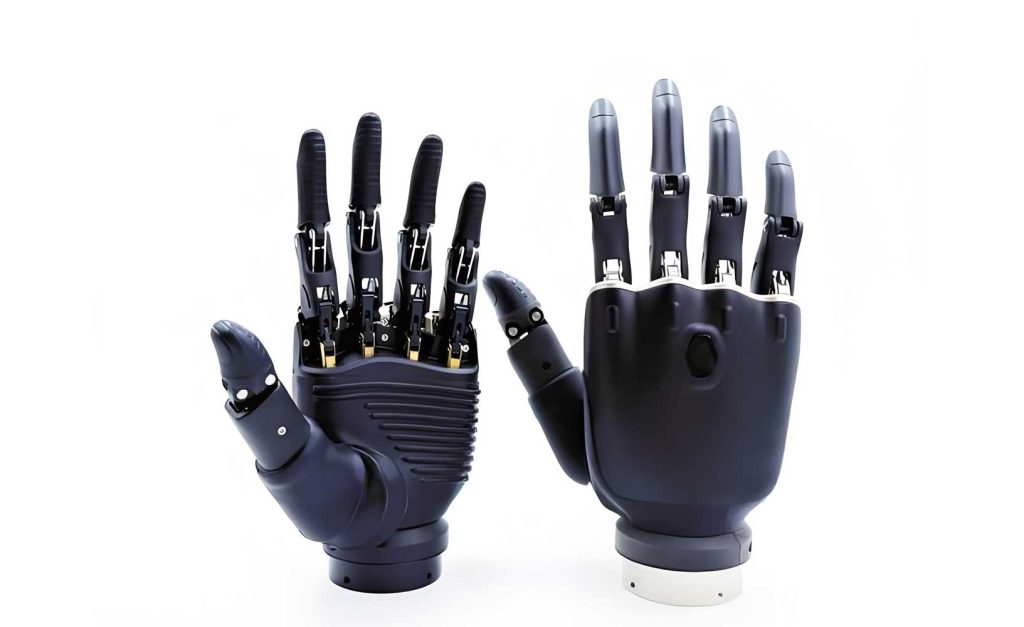
The human hand, through millennia of evolution, has achieved an optimal structure capable of grasping objects of various shapes and performing complex, precise manipulations. Inspired by this, the flexible multi-fingered dexterous robotic hand typically consists of five independent fingers, each mimicking the anatomical segments: the distal, middle, and proximal phalanges, along with the metacarpophalangeal joint. Each finger can perform bending motions at these joints, with the distal phalange often moving in conjunction with the middle phalange. Additionally, a rotational degree of freedom is incorporated at the base to simulate wrist movement. From a mechanical perspective, each bending motion corresponds to a rotational joint, giving a single finger three bending degrees of freedom and one rotational degree of freedom, totaling four degrees of freedom. This structure resembles a serial robotic manipulator, enabling kinematic analysis using established methods.
To model the motion of this dexterous robotic hand, we simplify its mechanism into a series of rigid links connected by rotational joints. Each joint’s movement determines the posture and position of subsequent links in a Cartesian coordinate system. We employ the Denavit-Hartenberg (D-H) parameter method, a widely used technique for attaching reference frames to robotic manipulator links. The D-H parameters include link length \(a\), twist angle \(\alpha\), offset \(d\), and joint angle \(\theta\). For a single finger of the dexterous robotic hand, we establish coordinate frames as shown in the simplified diagram, leading to the following D-H parameter table:
| Link | Twist Angle \(\alpha\) | Link Length \(a\) | Offset \(d\) | Joint Angle \(\theta\) |
|---|---|---|---|---|
| 1 | -90° | 0 | \(d_1\) | \(\theta_1\) |
| 2 | 0° | \(a_2\) | 0 | \(\theta_2\) |
| 3 | 0° | \(a_3\) | 0 | \(\theta_3\) |
| 4 | 0° | \(a_4\) | 0 | \(\theta_4\) |
In kinematics, transformations between coordinate frames are represented using homogeneous transformation matrices. The position and orientation of the fingertip in Cartesian space can be described by a series of such matrices. For adjacent links, the homogeneous transformation matrix from frame \(i-1\) to frame \(i\) is given by:
$$
T_i^{i-1} = \begin{bmatrix}
\cos\theta_i & -\sin\theta_i \cos\alpha_i & \sin\theta_i \sin\alpha_i & a_i \cos\theta_i \\
\sin\theta_i & \cos\theta_i \cos\alpha_i & -\cos\theta_i \sin\alpha_i & a_i \sin\theta_i \\
0 & \sin\alpha_i & \cos\alpha_i & d_i \\
0 & 0 & 0 & 1
\end{bmatrix}
$$
The overall transformation from the base frame to the fingertip frame is the product of these individual matrices:
$$
T_4^0 = T_1^0 \cdot T_2^1 \cdot T_3^2 \cdot T_4^3
$$
Substituting the D-H parameters from the table, we derive the forward kinematics model. The resulting matrix \(T_4^0\) can be expressed as:
$$
T_4^0 = \begin{bmatrix}
n_x & o_x & a_x & p_x \\
n_y & o_y & a_y & p_y \\
n_z & o_z & a_z & p_z \\
0 & 0 & 0 & 1
\end{bmatrix}
$$
where the orientation submatrix is denoted by \(Q = [n \quad o \quad a]\), and the position vector \(P = [p_x, p_y, p_z]^T\) represents the coordinates of the fingertip relative to the base frame. Specifically, the coordinates are computed as follows:
$$
p_x = a_2 \cos\theta_2 \cos\theta_1 + a_3 \cos(\theta_2 + \theta_3) \cos\theta_1 + a_4 \cos(\theta_2 + \theta_3 + \theta_4) \cos\theta_1
$$
$$
p_y = a_2 \cos\theta_2 \sin\theta_1 + a_3 \cos(\theta_2 + \theta_3) \sin\theta_1 + a_4 \cos(\theta_2 + \theta_3 + \theta_4) \sin\theta_1
$$
$$
p_z = d_1 + a_2 \sin\theta_2 + a_3 \sin(\theta_2 + \theta_3) + a_4 \sin(\theta_2 + \theta_3 + \theta_4)
$$
Here, \(p_x\), \(p_y\), and \(p_z\) are the spatial coordinates of the fingertip point P. This forward kinematics model provides the foundation for analyzing the workspace of the dexterous robotic hand. Since all fingers share similar mechanisms, the same approach applies to each finger of the multi-fingered dexterous robotic hand.
The workspace of a finger refers to the set of all points in Cartesian space that the fingertip can reach as the joints move within their allowable ranges. For this dexterous robotic hand, the primary motions include rotation at the base joint and bending at the three phalangeal joints. Determining the workspace is crucial for ensuring the dexterous robotic hand can effectively perform grasping tasks without missing target areas. Methods for workspace analysis include numerical, graphical, and analytical approaches. Due to the complexity of multi-degree-of-freedom systems, numerical methods like the Monte Carlo method are often preferred for their accuracy and applicability. The Monte Carlo method involves randomly sampling joint angles within their limits, computing the corresponding fingertip positions using the forward kinematics model, and accumulating these points to form the workspace boundary.
Based on biomechanical data, we consider the middle finger as an example. The lengths of the proximal, middle, and distal phalanges are approximately 44.5 mm, 28 mm, and 16.5 mm, respectively, with a metacarpal length of 50 mm. The joint angle ranges are: \(\theta_1\) (rotation) from -50° to 50°, \(\theta_2\) and \(\theta_3\) (bending) from 0° to 90°, and \(\theta_4\) (distal bending) from 0° to 60°. These parameters are summarized in the table below:
| Parameter | Description | Value |
|---|---|---|
| \(d_1\) | Metacarpal length | 50 mm |
| \(a_2\) | Proximal phalange length | 44.5 mm |
| \(a_3\) | Middle phalange length | 28 mm |
| \(a_4\) | Distal phalange length | 16.5 mm |
| \(\theta_1\) | Rotation joint angle | -50° to 50° |
| \(\theta_2\) | Proximal bending angle | 0° to 90° |
| \(\theta_3\) | Middle bending angle | 0° to 90° |
| \(\theta_4\) | Distal bending angle | 0° to 60° |
Using the Monte Carlo method, we implement a simulation in MATLAB. By iterating over all possible combinations of joint angles within their ranges, we compute the fingertip coordinates \(p_x\), \(p_y\), and \(p_z\). For visualization, we plot two-dimensional and three-dimensional workspace projections. When \(\theta_1\) is fixed at 0°, and \(\theta_2\), \(\theta_3\), \(\theta_4\) are varied, we obtain the X-Z plane workspace, as shown in the simulation results. The maximum ranges in the X and Z directions are approximately -50 mm to 100 mm and -40 mm to 50 mm, respectively. Similarly, fixing \(\theta_1\) at 90° yields the Y-Z plane workspace, with ranges around -40 mm to 80 mm in Y and -40 mm to 50 mm in Z. The full three-dimensional workspace is generated by varying all joint angles, producing a volumetric point cloud that represents the reachable space of the dexterous robotic hand.
The simulation results demonstrate that the workspace points are uniformly distributed and visually intuitive, providing a clear understanding of the dexterous robotic hand’s operational limits. This analysis is vital for optimizing the structural design of the dexterous robotic hand, ensuring it meets the requirements for rehabilitation tasks. For instance, by adjusting link lengths or joint angle limits, the workspace can be expanded or shaped to better mimic natural hand movements. The dexterous robotic hand’s ability to cover a broad and practical workspace enhances its effectiveness in assisting patients with hand motor recovery.
In conclusion, this study establishes a forward kinematics model for a flexible multi-fingered dexterous robotic hand using D-H parameters, deriving the spatial coordinates of the fingertip. Through the Monte Carlo method and MATLAB simulation, we analyze the two-dimensional and three-dimensional workspaces of the dexterous robotic hand. The results show a well-distributed and comprehensive workspace, offering valuable theoretical support for subsequent structural design optimizations. Future work may involve integrating inverse kinematics for real-time control, refining the dexterous robotic hand’s compliance for safer human-robot interaction, and exploring advanced materials to enhance flexibility. The dexterous robotic hand continues to be a pivotal innovation in medical robotics, with ongoing research aimed at improving its functionality and accessibility for rehabilitation applications.
To further elaborate on the kinematics, we can express the homogeneous transformation matrices explicitly. For joint 1:
$$
T_1^0 = \begin{bmatrix}
\cos\theta_1 & 0 & -\sin\theta_1 & 0 \\
\sin\theta_1 & 0 & \cos\theta_1 & 0 \\
0 & -1 & 0 & d_1 \\
0 & 0 & 0 & 1
\end{bmatrix}
$$
For joint 2:
$$
T_2^1 = \begin{bmatrix}
\cos\theta_2 & -\sin\theta_2 & 0 & a_2 \cos\theta_2 \\
\sin\theta_2 & \cos\theta_2 & 0 & a_2 \sin\theta_2 \\
0 & 0 & 1 & 0 \\
0 & 0 & 0 & 1
\end{bmatrix}
$$
For joint 3:
$$
T_3^2 = \begin{bmatrix}
\cos\theta_3 & -\sin\theta_3 & 0 & a_3 \cos\theta_3 \\
\sin\theta_3 & \cos\theta_3 & 0 & a_3 \sin\theta_3 \\
0 & 0 & 1 & 0 \\
0 & 0 & 0 & 1
\end{bmatrix}
$$
For joint 4:
$$
T_4^3 = \begin{bmatrix}
\cos\theta_4 & -\sin\theta_4 & 0 & a_4 \cos\theta_4 \\
\sin\theta_4 & \cos\theta_4 & 0 & a_4 \sin\theta_4 \\
0 & 0 & 1 & 0 \\
0 & 0 & 0 & 1
\end{bmatrix}
$$
Multiplying these matrices yields the comprehensive model. The dexterous robotic hand’s versatility stems from this kinematic structure, allowing it to approximate human hand dexterity. In rehabilitation, the dexterous robotic hand can be programmed to guide patients through specific trajectories within this workspace, promoting motor relearning.
Regarding workspace analysis, the Monte Carlo method’s efficiency can be enhanced by using random sampling techniques. The probability density function for joint angles is assumed uniform across their ranges. The number of samples \(N\) affects accuracy; we typically use \(N = 10^5\) to \(10^6\) points for dense coverage. The fingertip coordinates are computed as:
$$
P(\Theta) = f(\Theta)
$$
where \(\Theta = [\theta_1, \theta_2, \theta_3, \theta_4]^T\) and \(f\) is the forward kinematics function. The workspace volume \(V\) can be estimated by counting points within a bounding box and applying the formula:
$$
V \approx \frac{N_{\text{in}}}{N} \times V_{\text{box}}
$$
where \(N_{\text{in}}\) is the number of points inside the workspace, and \(V_{\text{box}}\) is the volume of the bounding box. This quantitative measure aids in comparing different designs of the dexterous robotic hand.
Moreover, the dexterous robotic hand’s performance depends on factors like joint torque, speed, and precision. Kinematic optimization can involve minimizing the condition number of the Jacobian matrix to improve manipulability within the workspace. The Jacobian matrix \(J\) relates joint velocities to fingertip velocities:
$$
\dot{P} = J(\Theta) \dot{\Theta}
$$
For our dexterous robotic hand, \(J\) is a 3×4 matrix due to the four joints and three-dimensional position output. Its elements are derived from partial derivatives of \(p_x\), \(p_y\), \(p_z\) with respect to \(\theta_i\). Analyzing \(J\) helps identify singularities where the dexterous robotic hand loses mobility, which is crucial for safe operation.
In practice, the dexterous robotic hand may incorporate sensors for force feedback and adaptive control. Integrating these aspects with workspace analysis ensures a holistic design. For example, by mapping the workspace to common grasping patterns—such as pinch, power, or cylindrical grasps—we can tailor the dexterous robotic hand’s movements for specific rehabilitation exercises. This customization enhances the dexterous robotic hand’s utility in clinical settings.
To summarize, the flexible multi-fingered dexterous robotic hand represents a significant advancement in assistive technology. Its workspace, derived through rigorous kinematic modeling and simulation, provides a foundation for innovation. As research progresses, we anticipate more sophisticated dexterous robotic hands with expanded capabilities, ultimately improving the quality of life for individuals with hand impairments. The continuous refinement of the dexterous robotic hand underscores its potential as a transformative tool in medical robotics.