
The pursuit of recreating the remarkable manipulation capabilities of the human hand has been a central challenge in robotics for decades. A truly dexterous robotic hand represents the pinnacle of this endeavor, serving as the crucial end-effector that directly interacts with the unstructured world. Its performance dictates a robotic system’s overall utility, adaptability, and intelligence. While single-degree-of-freedom grippers are prevalent, their inherent lack of adaptability and poor universality for grasping diverse objects has propelled research into multi-fingered, anthropomorphic designs. This article delves into the integrated process of designing, modeling, and controlling a dexterous robotic hand, with a focus on applications in assistive technology. I will discuss the bio-inspired mechanical design, kinematic simulation, derivation of a dynamic model using Lagrangian mechanics, and the implementation of an advanced adaptive control scheme capable of handling real-world uncertainties.
The fundamental motivation stems from the need to restore functional autonomy to individuals with upper-limb disabilities. A prosthetic dexterous robotic hand must not only replicate the aesthetic form of a human hand but, more importantly, its functional essence—the ability to perform both power grasps for stability and precision grasps for delicate manipulation. The control of such a complex system, often with 15 or more degrees of freedom, is typically decomposed into hierarchical strategies. At the low level, joint-space position or torque control is favored for its computational simplicity and avoidance of kinematic singularities. However, the highly nonlinear, coupled dynamics of a dexterous robotic hand, combined with inevitable modeling errors and external disturbances, pose significant challenges for conventional linear controllers. This necessitates the exploration of robust and adaptive control laws that can guarantee performance despite uncertainties.
Bio-Inspired Design Philosophy and Mechanical Architecture
The design of an effective dexterous robotic hand begins with a deep understanding of its biological counterpart. The human hand is a masterpiece of evolution, featuring a complex arrangement of bones, joints, ligaments, and tendons that allow for a vast range of motions. For a prosthetic or assistive device, key anthropometric data is considered, though practical constraints often necessitate slight modifications. The primary design goals include achieving a high power-to-weight ratio, ensuring reliability, and simplifying actuation and control where possible.
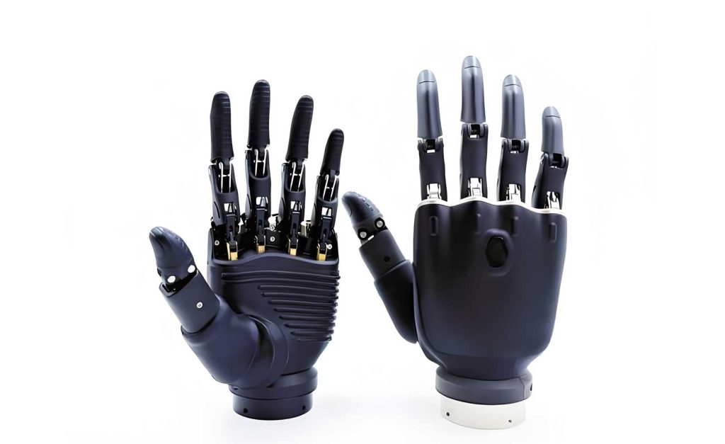
The proposed dexterous robotic hand follows a five-fingered, multi-joint architecture. For manufacturing and maintenance simplicity, the index, middle, ring, and little fingers are designed as identical modules. Each of these four fingers comprises two primary phalangeal segments, analogous to the proximal and intermediate phalanges, connected by revolute joints. The thumb, crucial for opposition and pinch grasps, requires independent kinematics and is often designed with at least two active degrees of freedom (abduction/adduction and flexion/extension).
The proximal segment (first module) serves as the critical link between the palm and the distal segment. Its primary motion is flexion/extension. It houses the driving mechanism—often a micro motor and gear train—that transmits torque to the distal joint. The distal segment (second module) completes the finger, typically with a padded, hemispherical tip to increase contact area and provide a soft grip. Connection between segments is achieved via robust linkage plates or direct bearing mounts. The palm acts as the central chassis, housing the actuators for the fingers and providing the foundational structure.
| Parameter | Biological Reference (Approx.) | Engineered Value (Example) | Rationale for Modification |
|---|---|---|---|
| Proximal Link Length (r1) | ~40-50 mm | 45 mm | Optimized for common object sizes and gearbox placement. |
| Distal Link Length (r2) | ~25-35 mm | 30 mm | Maintains functional length while reducing inertia. |
| Finger Mass (m1 + m2) | N/A | < 80 grams | Minimized to reduce actuator load and improve dynamic response. |
| Joint Range of Motion | 0-90° (MCP), 0-110° (PIP) | 0-100° (both joints) | Slightly expanded range to accommodate tool use. |
| Actuation Type | Tendons/Muscles | DC Micromotor with Planetary Gear | High torque density, compact size, and precise control. |
Kinematic Simulation for Functional Validation
Prior to physical prototyping, kinematic simulation in a digital environment like Siemens NX or SolidWorks is indispensable. It allows for the validation of range of motion, detection of mechanical interferences, and visualization of basic grasping primitives. For the simulation of a dexterous robotic hand, key functional tasks such as power grasping and targeted tapping are analyzed.
The simulation is built upon several simplifying assumptions: (1) All components are treated as rigid bodies, (2) mass is uniformly distributed for initial analysis, and (3) joint friction is initially neglected. The simulation process involves:
- Link Definition: The palm (including embedded motors) is defined as the fixed base link.
- Joint Definition: Each finger joint is modeled as a revolute joint. A kinematic chain is established from the palm to the fingertip.
- Driver Assignment: Prescribed motions are applied to the joints to emulate desired activities.
For a power grasp, constant angular velocities are applied to flex all finger joints simultaneously, causing the fingers to enclose a virtual cylindrical object. The thumb is driven with a coordinated motion to oppose the fingers.
For a tapping motion, a harmonic drive (e.g., sinusoidal function) is applied to the metacarpophalangeal (MCP) joint of a single finger, while the proximal interphalangeal (PIP) joint is held at a fixed angle, mimicking a light hammering action. These simulations provide a first-pass verification of the mechanical design’s feasibility.
| Simulation Task | Driven Joint(s) | Motion Law / Speed | Observation / Output |
|---|---|---|---|
| Power Grasp (Enclose) | All finger joints | Constant velocity: 5-9 rad/min | Collision-free enveloping of target object volume. |
| Precision Pinch | Thumb (2 joints) & Index finger | Coordinated trajectory | Tip-to-tip contact on a small virtual object. |
| Tapping / Hammering | Single Finger MCP joint | Harmonic: $q_d = A \sin(2\pi f t)$ | Cyclic motion with periodic contact event. |
Dynamic Modeling Using Lagrangian Formulation
To achieve high-performance control, especially for dynamic interactions, a mathematical model of the system’s dynamics is essential. For a dexterous robotic hand, the dynamics of a single finger can be effectively represented by a two-link, revolute-joint planar manipulator model, which captures the dominant inertial and gravitational effects. The general dynamics for an n-link rigid robot manipulator are given by the following equation:
$$
D(q)\ddot{q} + C(q, \dot{q})\dot{q} + G(q) = \tau + \omega
$$
where $q \in \mathbb{R}^n$ is the vector of joint angular displacements, $\dot{q}$ and $\ddot{q}$ are the joint velocities and accelerations, respectively. $D(q) \in \mathbb{R}^{n \times n}$ is the symmetric, positive-definite inertia matrix. $C(q, \dot{q}) \in \mathbb{R}^{n \times n}$ is the Coriolis and centripetal matrix. $G(q) \in \mathbb{R}^{n}$ is the gravitational torque vector. $\tau \in \mathbb{R}^{n}$ is the vector of control torques applied at the joints, and $\omega \in \mathbb{R}^{n}$ represents bounded unmodeled dynamics and external disturbances.
For a two-link finger model (Link 1: proximal, Link 2: distal), as shown in a simplified diagram, the Lagrangian method yields the following specific terms. Let $q = [q_1, q_2]^T$, $r_1$, $r_2$ be link lengths, $m_1$, $m_2$ be link masses, and $l_1$, $l_2$ be distances to the center of mass (often simplified as $l_i = r_i$).
Inertia Matrix $D(q)$:
$$
D(q) = \begin{bmatrix}
D_{11} & D_{12} \\
D_{21} & D_{22}
\end{bmatrix}
$$
where
$$
D_{11} = m_1 r_1^2 + m_2 (r_1^2 + r_2^2 + 2 r_1 r_2 \cos q_2) \\
D_{12} = D_{21} = m_2 (r_2^2 + r_1 r_2 \cos q_2) \\
D_{22} = m_2 r_2^2
$$
Coriolis and Centripetal Matrix $C(q, \dot{q})$:
$$
C(q, \dot{q}) = \begin{bmatrix}
-h \dot{q}_2 & -h (\dot{q}_1 + \dot{q}_2) \\
h \dot{q}_1 & 0
\end{bmatrix}
$$
where $h = m_2 r_1 r_2 \sin q_2$.
Gravitational Torque Vector $G(q)$:
Assuming gravity acts in the negative Y-direction of the base frame,
$$
G(q) = \begin{bmatrix}
(m_1 + m_2) g r_1 \cos q_1 + m_2 g r_2 \cos(q_1 + q_2) \\
m_2 g r_2 \cos(q_1 + q_2)
\end{bmatrix}
$$
where $g$ is the acceleration due to gravity.
This model exhibits the standard properties of robotic manipulators: $D(q)$ is symmetric and positive definite, $\dot{D}(q) – 2C(q,\dot{q})$ is skew-symmetric, and the dynamics are linear in a set of constant physical parameters $P$. This leads to the linear parameterization (LIP) form:
$$
D(q)\ddot{q} + C(q, \dot{q})\dot{q} + G(q) = Y(q, \dot{q}, \ddot{q}) P
$$
where $Y$ is the known regressor matrix and $P$ is the vector of unknown parameters. For our two-link dexterous robotic hand finger, one possible parameter set is $P = [p_1, p_2, p_3]^T = [m_1 r_1^2 + m_2 r_1^2, m_2 r_2^2, m_2 r_1 r_2]^T$. This property is foundational for adaptive control design.
Adaptive Robust Control Strategy
Linear PID control, while widely used, often struggles with the nonlinear, time-varying dynamics of a dexterous robotic hand, particularly during contact transitions or when carrying variable loads. Simply increasing gain values leads to instability and high-frequency chatter. A more sophisticated approach combines a nonlinear PD structure with adaptive robust terms to handle parametric uncertainties (e.g., unknown payload mass) and non-parametric disturbances (e.g., friction, unmodeled dynamics) with an unknown bound.
Let $q_d(t)$ be the desired smooth joint trajectory. Define the tracking error $e = q – q_d$ and the filtered tracking error $s = \dot{e} + \Lambda e$, where $\Lambda$ is a positive definite matrix. The control objective is to drive $e$ and $\dot{e}$ to zero.
The proposed controller has the following structure:
$$
\tau = -K_p e – K_v \dot{e} + \hat{G}(q) – \hat{\eta} \cdot \text{sgn}(s)
$$
where $K_p$ and $K_v$ are nonlinear, error-dependent gain matrices, $\hat{G}(q)$ is the estimated gravitational compensation, and the last term is a robust feedback term with an adaptive estimate $\hat{\eta}$ of the disturbance bound.
1. Nonlinear PD Gains:
To achieve improved transient and steady-state performance, the gains are designed to vary with the magnitude of error:
$$
K_p = K_{p1} + K_{p2} \cdot \Phi_p(||e||), \quad K_v = K_{v1} + K_{v2} \cdot \Phi_v(||\dot{e}||)
$$
where $K_{p1}, K_{p2}, K_{v1}, K_{v2}$ are constant positive diagonal matrices, and $\Phi_p(\cdot), \Phi_v(\cdot)$ are monotonically increasing functions (e.g., saturation functions or simple scalars). This provides higher gain when errors are large for fast convergence and lower gain near equilibrium to minimize overshoot and sensitivity to noise.
2. Adaptive Robust Term & Parameter Estimation:
The disturbance $\omega$ is assumed to be bounded by an unknown constant $\eta$, i.e., $||\omega|| \leq \eta$. An adaptive law is used to estimate this bound online:
$$
\dot{\hat{\eta}} = \gamma ||s||_1
$$
where $\gamma > 0$ is the adaptation rate. This term ensures robustness against disturbances with unknown magnitude.
Furthermore, to handle parametric uncertainties in $P$, an adaptive law can be derived based on the LIP property. Using the tracking error dynamics, the parameter update law is:
$$
\dot{\hat{P}} = -\Gamma Y^T(q, \dot{q}, \ddot{q}_r, \dot{q}_r) s
$$
where $\hat{P}$ is the estimate of $P$, $\Gamma$ is a positive definite adaptation gain matrix, and $\ddot{q}_r = \ddot{q}_d – \Lambda \dot{e}$ is a reference acceleration. The full adaptive controller would then be:
$$
\tau = Y(q, \dot{q}, \ddot{q}_r, \dot{q}_r) \hat{P} – K_d s – \hat{\eta} \cdot \text{sgn}(s)
$$
where $K_d$ is a positive definite damping matrix.
Stability analysis using Lyapunov theory (with a candidate function $V = \frac{1}{2} s^T D(q) s + \frac{1}{2} \tilde{P}^T \Gamma^{-1} \tilde{P} + \frac{1}{2\gamma} \tilde{\eta}^2$, where $\tilde{P}=P-\hat{P}$ and $\tilde{\eta}=\eta-\hat{\eta}$) can demonstrate that all signals are bounded and the tracking error $s$ asymptotically converges to zero, implying convergence of $e$ and $\dot{e}$.
| Control Method | Key Principle | Advantages | Challenges for Dexterous Hands |
|---|---|---|---|
| Linear PID | Proportional, Integral, Derivative error feedback. | Simple, easy to tune, widely implemented. | Poor performance under nonlinear dynamics and variable loads; high gains cause instability. |
| Computed Torque Control (CTC) | Uses full dynamic model to linearize and decouple the system. | Excellent performance if model is accurate. | Extremely sensitive to model inaccuracies and disturbances; computationally heavy for full hand. | Sliding Mode Control (SMC) | Forces system state onto a predefined sliding surface with robust switching. | Very robust to bounded disturbances and parameter variations. | Chattering phenomenon (high-frequency control switching) can excite unmodeled dynamics and damage actuators. |
| Adaptive Robust Control (Proposed) | Combines nonlinear PD, adaptive parameter estimation, and robust disturbance rejection. | Handles parametric uncertainty and disturbances with unknown bounds; smoother than pure SMC. | More complex design and tuning; requires persistence of excitation for full parameter convergence. |
Simulation Results and Performance Analysis
To validate the proposed adaptive controller for a joint of the dexterous robotic hand, a simulation was conducted in MATLAB/Simulink using the two-link dynamic model. The following parameters were used: $r_1 = 0.045 \text{ m}$, $r_2 = 0.030 \text{ m}$, $m_1 = 0.040 \text{ kg}$, $m_2 = 0.025 \text{ kg}$. The desired trajectory for both joints was set to $q_{d1} = q_{d2} = \sin(2\pi t)$ rad. A bounded disturbance $\omega = [0.5\sin(10t), 0.3\cos(15t)]^T$ N·m was injected. The controller gains were selected as $K_{p1}=\text{diag}(180,190)$, $K_{p2}=\text{diag}(150,150)$, $K_{v1}=\text{diag}(180,180)$, $K_{v2}=\text{diag}(150,150)$, $\Lambda=\text{diag}(10,10)$, and adaptation gains $\gamma=0.1$, $\Gamma=\text{diag}(5,5,5)$.
The results demonstrated effective tracking. The joint angles $q_1$ and $q_2$ closely followed their desired sinusoidal trajectories $q_{d1}$ and $q_{d2}$. The tracking error for each joint remained within a $\pm 0.02$ rad ($\approx \pm 1.15^\circ$) envelope, which is well within acceptable limits for most manipulation tasks performed by a dexterous robotic hand. The control torques generated were smooth and realizable by typical micro motors, without exhibiting the severe chattering seen in standard sliding mode control. The adaptive parameter estimates $\hat{p}_1$, $\hat{p}_2$, $\hat{p}_3$ converged to values close to their true counterparts, and the disturbance bound estimate $\hat{\eta}$ increased to a steady-state value that encompassed the actual disturbance magnitude. These simulations confirm that the controller maintains robustness and performance even when the dynamic parameters are not precisely known and in the presence of persistent external disturbances, a common scenario for a dexterous robotic hand interacting with objects.
Discussion and Future Directions
The journey from a bio-inspired concept to a functionally autonomous dexterous robotic hand is multidisciplinary, integrating mechanical design, sensor integration, and intelligent control. The adaptive control framework discussed provides a solid foundation for managing the inherent uncertainties in such a system. However, several frontiers remain open for research to advance the capabilities of the dexterous robotic hand.
Tendon-Driven Actuation and Underactuation: Many advanced dexterous robotic hand designs, like the Shadow Hand or those from Yale and IIT, utilize tendon-driven mechanisms. This allows for remote placement of bulky actuators, reducing hand inertia. Underactuation, where fewer actuators than degrees of freedom are used (e.g., one motor driving multiple joints via differential mechanisms or compliant elements), can simplify control and reduce cost while still enabling complex, adaptive grasps. Modeling and controlling these systems introduces additional dynamics (tendon elasticity, friction) and non-holonomic constraints.
High-Dimensional Control and Grasp Planning: Controlling a full dexterous robotic hand with 15-20 DOFs in real-time is computationally demanding. Hierarchical control architectures are essential. At the high level, task planning and grasp synthesis algorithms determine the optimal hand posture and contact points for a given object. This information is then converted into joint trajectories, which are tracked by the low-level joint controllers described in this article. Machine learning, particularly deep reinforcement learning, is showing great promise in learning complex, sensorimotor policies for in-hand manipulation directly from data.
Tactile Sensing and Force/Impedance Control: True dexterity requires rich sensory feedback. Integrating tactile sensor arrays on the fingertips and phalanges of a dexterous robotic hand is critical for detecting slip, measuring contact forces, and identifying object properties. This sensory data enables advanced control paradigms like force control and impedance control. Instead of just tracking a position trajectory, the controller regulates the interaction force or the dynamic relationship between force and motion (impedance), allowing for safe and compliant interaction with fragile objects or uncertain environments.
Applications Beyond Prosthetics: While assistive devices are a primary motivator, the technology of the dexterous robotic hand has broad applications. In industrial settings, they can perform complex assembly tasks. In space robotics, they enable remote maintenance. In hazardous environments, they can handle dangerous materials. Each application domain imposes its own set of requirements on robustness, durability, and level of autonomy.
Conclusion
The development of a functional dexterous robotic hand is a multifaceted engineering challenge that sits at the intersection of biomechanics, dynamics, and control theory. This article has outlined a coherent development pipeline, starting from an anthropomorphic mechanical design validated through kinematic simulation. It emphasized the critical importance of an accurate dynamic model, derived via the Lagrangian method, which reveals the system’s nonlinear and coupled nature. To effectively command this complex system in the presence of uncertainties, an adaptive robust control strategy was presented and analyzed. This controller synergistically combines nonlinear PD action for performance shaping, online parameter adaptation to account for unknown inertial properties, and a robust term to reject disturbances with unknown bounds. Simulation studies validate that this approach ensures precise trajectory tracking and robustness, which are fundamental for reliable manipulation. As sensor technology, materials, and computational intelligence continue to advance, the next generation of dexterous robotic hands will move closer to achieving the graceful adaptability and versatile manipulation skills of the human hand, profoundly impacting fields from personal assistive robotics to advanced manufacturing and exploration.