
As an engineer deeply involved in the field of agricultural robotics, I find the design of the end effector to be one of the most critical and challenging aspects of developing a functional system. The end effector is the direct interface between the robot and its environment, responsible for tasks ranging from delicate fruit harvesting to robust seed planting. The unique and often harsh conditions of agricultural operations demand a specialized approach to end effector design, distinct from that used in controlled industrial settings. This discussion will explore my perspective on the methodologies for designing these crucial components, emphasizing practical considerations, analytical models, and material choices.
The overarching goal in agricultural robotics is to create systems that are cost-effective, reliable, and adaptable. Unlike factory floors, agricultural environments are characterized by variability—in lighting, terrain, and the objects being manipulated—as well as by the presence of dust, moisture, and abrasive materials. Therefore, the end effector must not only perform its primary function but also withstand these environmental stresses. A key design philosophy I adhere to is the principle of “sufficient complexity.” The mechanism should be as simple as possible to perform the task reliably, avoiding unnecessary degrees of freedom or precision that drive up cost and reduce robustness. For mobile platforms, wheeled robots offer a compelling balance of speed, stability, and simplicity, making them a prevalent base for many agricultural applications.
Fundamental Design Considerations for the Agricultural End Effector
When initiating the design of an agricultural robot’s end effector, several core principles guide my decisions:
- Environmental Hardening: Sealing critical joints, bearings, and actuators against dust, mud, and water ingress is paramount. This often involves the use of gaskets, bellows, or protective shrouds.
- Material Selection for Durability and Cost: The choice of materials directly impacts longevity and price. Aluminum alloys and stainless steel offer excellent corrosion resistance for structural parts. For lighter-duty or non-load-bearing components, engineering plastics (e.g., polycarbonate, POM) or composite resins can significantly reduce weight and cost while resisting chemical and environmental degradation.
- Modularity and Interchangeability: Given the seasonal nature of farming, a single robot might be required for seeding, weeding, and harvesting at different times of the year. Designing a modular interface between the robot arm and the end effector allows for quick tool changes, vastly improving the machine’s utility and economic value.
- Power and Actuation Strategy: Many fields lack readily available three-phase power or pneumatic/hydraulic infrastructure. Thus, electrically driven end effectors, powered by the robot’s onboard battery or a single-phase supply, are often the most practical solution. This influences the choice of motors and transmission systems.
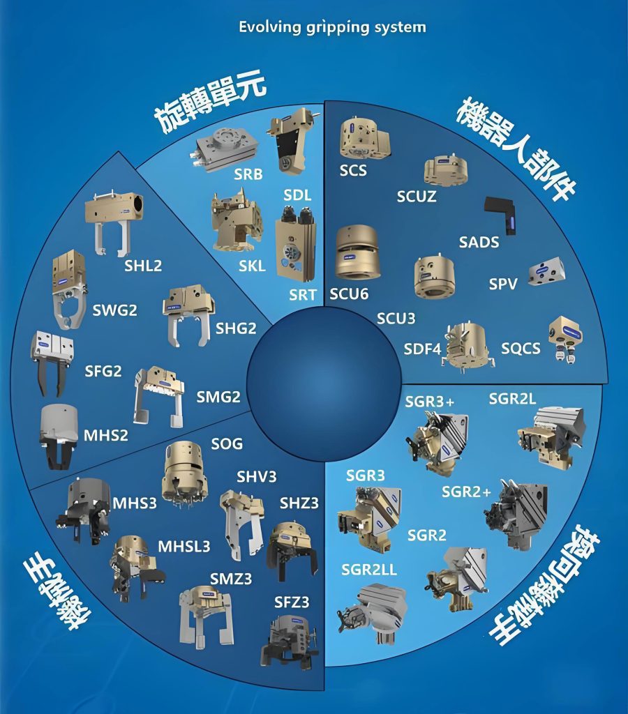
Wrist and Manipulator Structure
The wrist connects the end effector to the robot’s arm and determines its orientational dexterity. While a three-degree-of-freedom (3-DOF) wrist allows full orientation control, it introduces complexity, cost, weight, and potential points of failure. For many agricultural tasks, a 2-DOF or even a 1-DOF wrist is sufficient. For example, a simple rotational joint about the arm’s axis, combined with the arm’s own positioning, can often place the end effector in an adequate orientation for grasping or tool use. The governing principle is to minimize the weight and inertia at the extremity of the arm. The torque $\\tau_{motor}$ required at the arm’s joint to hold a mass $m$ at a distance $l$ is given by:
$$ \tau_{motor} = m \cdot g \cdot l \cdot \cos(\theta) $$
where $g$ is gravity and $\\theta$ is the angle from the horizontal. Reducing mass $m$ at the end effector directly reduces the required motor size and power consumption in the arm. In some designs, it is advantageous to locate the wrist’s actuator back along the arm and transmit motion via belts or linkages, further reducing the mass at the wrist itself.
The manipulator, or gripper, is the business end of the end effector. The most common design is the two-fingered gripper, which can be categorized by its finger motion:
| Type | Motion Description | Advantages | Typical Use in Agriculture |
|---|---|---|---|
| Translational | Fingers move parallel to each other. | Centers object reliably; uniform grip force. | Handling packaged goods, potted plants. |
| Rotational (Angular) | Fingers rotate about a pivot point. | Mechanically simple; can generate high grip force near tips. | Grasping irregular fruits, stems, or tools. |
The design challenge intensifies when the end effector must handle delicate, variable biological products like fruits. The grip force must be carefully calibrated to prevent bruising (excessive force) or dropping (insufficient force). This often requires the integration of force/torque sensors and compliant elements (like soft pads or under-actuated mechanisms) into the end effector design. The required grip force $F_g$ to hold an object of weight $W$ with a coefficient of friction $\\mu$ between the gripper pad and the object is:
$$ F_g \ge \frac{W}{2\mu} $$
This simple model highlights the importance of surface material (affecting $\\mu$) in designing a gentle yet secure end effector.
Actuation and Drive System Selection
The choice of drive system for the end effector is fundamental to its performance and practicality. The table below summarizes the primary options:
| Actuation Type | Power Source | Advantages | Disadvantages | Suitability for Agriculture |
|---|---|---|---|---|
| Electric Motor | On-board Battery / Grid | Clean, precise control, readily available, easy to seal. High power density, fast response, high force. | Can be bulky for high torque, requires power management. | Very High. Ideal for most mobile and precise tasks. |
| Hydraulic | On-board Pump / External Unit | High power density, fast response, high force. | Complex, prone to leaks, requires pump and reservoir, sensitive to contamination. | Medium. Suitable for heavy-duty, stationary applications (e.g., large bale handling). |
| Pneumatic | On-board Compressor / External Supply | Fast, simple, low cost, tolerant of minor leaks. | Lower force, compressible medium makes precise position control difficult, requires dry air. | Medium-High. Good for simple gripping and blowing actions if air supply is available. |
For the reasons outlined, my design preference often leans towards electric servo motors or stepper motors. Stepper motors, in particular, are well-suited for open-loop control in agricultural end effectors where absolute precision is secondary to reliability and cost. They provide good holding torque and can be controlled directly with digital pulses. Key characteristics I look for in an electric motor for an end effector include:
– High Torque-to-Volume/Weight Ratio: To minimize the size and weight added to the arm’s tip.
– Sufficient Speed Range: To allow for both fast approach and careful, slow manipulation.
– High Starting Torque: To overcome static friction and initiate movement reliably.
– Robustness: Ability to handle frequent start-stop cycles and brief overloads common in pick-and-place operations.
Motor Sizing and Selection Methodology
Selecting the correct motor is a systematic process. The primary parameters to determine are the motor’s maximum required torque, speed range, and consequently, power. The process often involves modeling the worst-case loading scenario for the end effector’s joint.
Step 1: Calculate Total Load Torque at the Joint. The torque $\\tau_{total}$ that the motor (through a reducer) must overcome consists of three components:
1. Acceleration Torque ($\\tau_{acc}$): Needed to overcome the inertia of the moving parts to achieve a desired angular acceleration $\\alpha$.
2. Friction Torque ($\\tau_{fric}$): Due to bearings, seals, and gear meshing.
3. Load Torque ($\\tau_{load}$): Torque due to the external force or weight the end effector is working against (e.g., gripping force, gravity on a payload).
Thus, $$ \tau_{total} = \tau_{acc} + \tau_{fric} + \tau_{load} $$
The acceleration torque is calculated using the rotational form of Newton’s second law: $\\tau_{acc} = J_{total} \\cdot \\alpha$, where $J_{total}$ is the total moment of inertia reflected to the motor shaft.
Step 2: Determine Required Motor Torque and Speed. If the joint uses a gearbox or transmission with a ratio $N$ (where $N > 1$ for reduction) and an efficiency $\\eta_{gb}$, and possibly other transmission elements like belts with efficiency $\\eta_{belt}$, the required motor torque $\\tau_{motor}$ is:
$$ \tau_{motor} = \frac{\tau_{total}}{N \cdot \eta_{gb} \cdot \eta_{belt}} $$
The required motor speed $\\omega_{motor}$ is related to the desired output joint speed $\\omega_{joint}$ by:
$$ \omega_{motor} = N \cdot \omega_{joint} $$
Step 3: Calculate Required Motor Power. The continuous power rating of the motor must satisfy:
$$ P_{motor} \ge \tau_{motor} \cdot \omega_{motor} $$
It is crucial to select a motor whose peak torque capability exceeds the calculated $\\tau_{motor}$ for the dynamic acceleration phase.
This calculation can be summarized in a parameter selection workflow:
| Parameter | Symbol | Calculation / Source | Notes |
|---|---|---|---|
| Load Inertia | $J_{load}$ | CAD model or physical measurement. | Reflect to motor shaft using $N^2$. |
| Motor/Reducer Inertia | $J_{motor}, J_{gb}$ | Manufacturer datasheet. | |
| Total Reflected Inertia | $J_{total}$ | $J_{total} = J_{motor} + J_{gb} + \\frac{J_{load}}{N^2}$ | |
| Max Angular Acceleration | $\\alpha_{max}$ | Based on desired cycle time. | |
| Acceleration Torque | $\\tau_{acc}$ | $\\tau_{acc} = J_{total} \\cdot \\alpha_{max}$ | |
| Friction Torque | $\\tau_{fric}$ | Estimated or measured. | Often 5-10% of rated torque. |
| External Load Torque | $\\tau_{load}$ | From task analysis (e.g., $F_g \\times$ moment arm). | |
| Total Output Torque | $\\tau_{total}$ | $\\tau_{total} = \\tau_{acc} + \\tau_{fric} + \\tau_{load}$ | Key output. |
| Gear Ratio & Efficiencies | $N, \\eta_{gb}, \\eta_{belt}$ | Chosen from catalog, known values. | |
| Required Motor Torque | $\\tau_{motor}$ | $\\tau_{motor} = \\frac{\\tau_{total}}{N \\cdot \\eta_{gb} \\cdot \\eta_{belt}}$ | Key output. |
| Required Joint Speed | $\\omega_{joint}$ | Based on task speed. | |
| Required Motor Speed | $\\omega_{motor}$ | $\\omega_{motor} = N \\cdot \\omega_{joint}$ | Key output. |
| Required Motor Power | $P_{motor}$ | $P_{motor} = \\tau_{motor} \\cdot \\omega_{motor}$ | Key output. |
Integration of Sensing and Compliance
A modern agricultural end effector is rarely a purely mechanical device. Integrating sensing and compliance is essential for handling delicate and variable produce. Key integrations include:
– Tactile/Force Sensing: Strain gauges or flexible force sensors in the fingers can provide feedback for closed-loop grip force control, ensuring a firm but non-damaging grasp.
– Proximity and Vision: While often located on the arm or robot body, visual feedback directly informs the end effector’s action. Sometimes simple infrared or ultrasonic sensors on the end effector itself guide final approach.
– Passive Compliance: Using materials with controlled elasticity (e.g., silicone pads) or mechanical designs like under-actuated linkages or series elastic actuators (SEAs). An under-actuated gripper with compliant joints can conform to an object’s shape without complex control, distributing grip force evenly. The effective stiffness $k_{eff}$ of such a compliant end effector can be modeled to predict its deformation $\\delta$ under load $F$: $$ F = k_{eff} \cdot \delta $$ This compliance is vital for preventing damage during unexpected contacts.
Performance Modeling and Simulation
Before physical prototyping, I extensively use simulation tools to model end effector performance. This involves multi-body dynamics simulations to validate motion ranges, check for collisions, and calculate forces and torques. Finite Element Analysis (FEA) is used to ensure structural components can handle operational stresses without failure and to optimize for weight reduction. The stress $\\sigma$ in a critical component under bending moment $M$ can be approximated by the flexure formula:
$$ \sigma = \frac{M \cdot c}{I} $$
where $c$ is the distance from the neutral axis and $I$ is the area moment of inertia. Simulation allows iterative optimization of these geometric parameters ($c$, $I$) to achieve a safe, lightweight design for the end effector structure.
Prototyping and Field Testing Iteration
No design process is complete without real-world validation. Prototypes are built using the selected materials (e.g., 3D-printed plastics for initial forms, machined aluminum for final versions) and integrated with motors and basic control logic. Field testing reveals unforeseen challenges: how the end effector performs with real, dirty produce; how sensors behave in direct sunlight; how materials degrade with exposure to plant sap or soil. This iterative loop—design, model, prototype, test—is essential for refining the end effector into a robust agricultural tool. Metrics like success rate (successful grasps/attempts), cycle time, and damage rate are quantitatively measured.
Future Trends and Advanced Concepts
The future of agricultural end effectors lies in increased intelligence, adaptability, and soft robotics principles. Research is active in:
– Variable Geometry End Effectors: Grippers that can radically change shape to handle vastly different objects, from a berry to a vegetable.
– Bio-inspired Designs: Mimicking the grasping strategies of animals or the coiling of plant tendrils.
– Embedded Perception: Cameras and tactile sensors distributed within the end effector structure itself, providing rich, localized feedback for in-hand manipulation.
– Multi-Functional Tools: An end effector that integrates a gripper, a cutter, and a nozzle for spraying or suction, controlled to perform compound tasks like “select, cut, and place.”
In conclusion, designing an end effector for agricultural robotics is a multifaceted engineering challenge that balances mechanical design, actuation selection, material science, and control integration. The process must be deeply rooted in the practical realities of the farm environment, prioritizing robustness, simplicity, and cost-effectiveness alongside functional performance. By applying systematic methodologies—from first-principles calculations and motor sizing to iterative prototyping—we can develop end effectors that significantly advance the automation and precision of agriculture. The continued evolution of this field promises to yield ever more capable and gentle end effectors, expanding the horizons of what agricultural robots can achieve.