
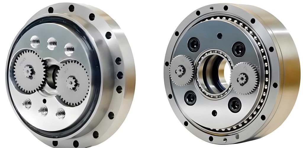
In the field of precision machinery and robotics, rotary vector reducers play a critical role due to their compact design and high torque transmission capabilities. As a researcher focused on mechanical system analysis, I have extensively studied the main bearings used in these reducers, which are often angular contact ball bearings with thin-walled and multi-ball structures. The increasing demand for miniaturization and efficiency in rotary vector reducers has led to bearings with a large number of balls, but this complicates the analysis of forces and deformations. Traditional quasi-static models, while effective for high-speed and heavy-load applications, involve solving nonlinear equations whose number scales with the ball count, resulting in slow computational speeds. In this article, I present a simplified analytical method based on the Newton-Raphson algorithm to address this challenge, enabling faster and accurate analysis of main bearings in rotary vector reducers under combined radial, axial, and moment loads. The method leverages the similarity in contact conditions among adjacent balls, reducing equation counts and improving efficiency without compromising precision. Throughout this discussion, I will emphasize the application to rotary vector reducers, as their unique requirements drive the need for such innovative approaches.
The quasi-static model for angular contact ball bearings in rotary vector reducers is founded on Hertzian contact theory and accounts for five degrees of freedom (5-DOF) displacements, including translations and rotations. In my analysis, I consider a bearing where the outer ring is fixed, and the inner ring undergoes offsets δx, δy, δz along the x, y, z axes and angular rotations θx, θy about the x and y axes. The coordinate system is centered at the bearing origin, with the z-axis aligned along the axial direction. For a bearing with Z balls, the angular position of the j-th ball is given by ψj = 2π(j – 1)/Z + γ, where γ is the position angle of the first ball. The initial geometry involves the distance A between the inner and outer raceway groove curvature centers and the initial contact angle α0. Under load, the axial and radial distances between these centers change, leading to new contact angles and deformations.
To derive the relationships, let A1j and A2j represent the axial and radial distances after loading for the j-th ball. These are expressed as:
$$ A_{1j} = A \sin \alpha_0 + \delta_z + G_i \theta_x \sin \psi_j + G_i \theta_y \cos \psi_j $$
$$ A_{2j} = A \cos \alpha_0 + \delta_x \cos \psi_j + \delta_y \sin \psi_j $$
where Gi is the inner raceway turning radius, defined as Gi = D_{pw}/2 + (f_i D_w – D_w/2) \cos \alpha_0, with D_{pw} as the pitch circle diameter, D_w as the ball diameter, and f_i as the inner groove curvature radius coefficient. The contact deformations δij and δej for the inner and outer raceways, respectively, are related to the distances X1j and X2j from the ball center to the outer raceway curvature center. The geometric compatibility equations are:
$$ (A_{1j} – X_{1j})^2 + (A_{2j} – X_{2j})^2 – [(f_i – 0.5)D_w + \delta_{ij}]^2 = 0 $$
$$ X_{1j}^2 + X_{2j}^2 – [(f_e – 0.5)D_w + \delta_{ej}]^2 = 0 $$
where f_e is the outer groove curvature radius coefficient. From these, the actual contact angles αij and αej can be derived as functions of the distances, simplifying the system by halving the number of unknowns. The transformations are:
$$ \delta_{ij} = \frac{A_{1j} \cos \alpha_{ej} – A_{2j} \sin \alpha_{ej}}{\sin(\alpha_{ij} – \alpha_{ej})} – (f_i – 0.5)D_w $$
$$ \delta_{ej} = \frac{A_{2j} \sin \alpha_{ij} – A_{1j} \cos \alpha_{ij}}{\sin(\alpha_{ij} – \alpha_{ej})} – (f_e – 0.5)D_w $$
$$ X_{1j} = \frac{A_{2j} \tan \alpha_{ij} – A_{1j}}{\tan \alpha_{ij} – \tan \alpha_{ej}} \tan \alpha_{ej} $$
$$ X_{2j} = \frac{A_{2j} \tan \alpha_{ij} – A_{1j}}{\tan \alpha_{ij} – \tan \alpha_{ej}} $$
The force equilibrium for each ball considers the normal contact loads Qij and Qej, centrifugal force Fcj, gyroscopic moment Mgj, and frictional effects. Based on Hertzian theory, the contact loads relate to deformations as Qij = K_{ij} \delta_{ij}^{1.5} and Qej = K_{ej} \delta_{ej}^{1.5}, where K_{ij} and K_{ej} are load-displacement coefficients. The centrifugal force and gyroscopic moment are given by:
$$ F_{cj} = \frac{1}{2} m D_{pw} \omega_{mj}^2 $$
$$ M_{gj} = J \omega_{mj} \omega_{Rj} \sin \beta_j $$
Here, m is the ball mass, ωmj is the orbital angular velocity, J is the ball’s moment of inertia, ωRj is the spin angular velocity, and βj is the ball attitude angle. Assuming that gyroscopic moments are resisted by friction at the outer raceway, with control coefficients λij = 0 and λej = 2, the force balance equations for a single ball in vertical and horizontal directions are:
$$ Q_{ij} \sin \alpha_{ij} – Q_{ej} \sin \alpha_{ej} – \frac{M_{gj}}{D_w} (\lambda_{ij} \cos \alpha_{ij} – \lambda_{ej} \cos \alpha_{ej}) = 0 $$
$$ Q_{ij} \cos \alpha_{ij} – Q_{ej} \cos \alpha_{ej} + \frac{M_{gj}}{D_w} (\lambda_{ij} \sin \alpha_{ij} – \lambda_{ej} \sin \alpha_{ej}) + F_{cj} = 0 $$
For the entire bearing, the equilibrium equations under external loads Fx, Fy, Fz and moments Mx, My are summed over all balls. The system is nonlinear and typically solved using the Newton-Raphson algorithm. However, for rotary vector reducers with many balls, this leads to 2Z + 5 equations, which are computationally intensive. To address this, I propose a simplified analytical method that groups adjacent balls, assuming they have similar contact angles, loads, and deformations. If k adjacent balls are treated as identical, the number of equations reduces significantly. For instance, if Z is divisible by k, the simplified ball count becomes N = Z/k, and the equilibrium equations are modified. The x-direction force balance, for example, transforms to:
$$ F_x – k \sum_{j=1}^{N} \left( Q_{ij} \cos \alpha_{ij} + \frac{\lambda_{ij} M_{gj}}{D_w} \sin \alpha_{ij} \right) \cos \psi’_j = 0 $$
where ψ’_j = 2π(j – 1)k/Z + γ. If Z is not divisible, with remainder h, the equation adjusts to include the remaining balls separately. This grouping reduces computational effort while maintaining accuracy, as demonstrated in later sections.
The simplified analysis method follows a structured workflow. First, static conditions are solved to obtain initial parameters like contact angles and displacements. Then, assuming constant displacement parameters, dynamic effects such as centrifugal forces and gyroscopic moments are incorporated to iteratively update contact angles using the ball equilibrium equations. Next, the bearing equilibrium equations are solved for new displacements, and the process repeats until convergence. A relaxation factor is introduced in the Newton-Raphson algorithm to ensure stability and avoid divergence. The key innovation lies in the grouping step, where k adjacent balls are considered identical, effectively reducing the number of variables. This approach is particularly beneficial for rotary vector reducers, where bearings often have over 50 balls, leading to substantial time savings.
To validate the method, I applied it to a specific main bearing used in a rotary vector reducer: the H76/182RV angular contact ball bearing. Its parameters are summarized in the table below.
| Parameter | Value |
|---|---|
| Ball Diameter, D_w (mm) | 10.32 |
| Pitch Circle Diameter, D_{pw} (mm) | 197.98 |
| Initial Contact Angle, α_0 (°) | 40 |
| Number of Balls, Z | 51 |
| Inner Raceway Radius, r_i (mm) | 5.26 |
| Outer Raceway Radius, r_e (mm) | 5.37 |
In the analysis, I considered a rotational speed of 40 r/min, with applied loads F_y = 4000 N, F_z = 13720 N, and moment M_y = 2450 N·m. The grouping factor k was varied as 1, 2, 3, and 4, where k=1 represents the original unsimplified method. The results for the normal load and contact angle of the first ball with the inner raceway are shown in the following tables and formulas. For instance, the normal load Q_{i1} can be expressed as a function of deformation:
$$ Q_{i1} = K_{i1} \delta_{i1}^{1.5} $$
where δ_{i1} is derived from the geometric relations. The computed values demonstrate that as k increases, the results remain close to the unsimplified case, with errors within acceptable limits.
| Grouping Factor k | Normal Load Q_{i1} (N) | Contact Angle α_{i1} (°) | Relative Error in Q_{i1} (%) |
|---|---|---|---|
| 1 (Original) | 1250.3 | 42.5 | 0.0 |
| 2 | 1248.7 | 42.6 | 0.13 |
| 3 | 1245.9 | 42.7 | 0.35 |
| 4 | 1243.2 | 42.8 | 0.57 |
The relative errors are minimal, indicating that the simplification does not compromise accuracy. To further assess efficiency, I measured computation times under various operating conditions, covering speeds from 20 to 200 r/min and load coefficients m from 1 to 10, where axial load F_z = 1372m N, radial load F_y = 500m N, and moment M_y = 245m N·m. The results are summarized below.
| Speed (r/min) | Load Coefficient m | k=1 | k=2 | k=3 | k=4 |
|---|---|---|---|---|---|
| 40 | 2 | 322 | 180 | 126 | 99 |
| 4 | 282 | 167 | 116 | 95 | |
| 6 | 259 | 144 | 102 | 80 | |
| 8 | 256 | 144 | 102 | 80 | |
| 10 | 284 | 150 | 98 | 77 | |
| 80 | 2 | 364 | 193 | 134 | 103 |
| 4 | 306 | 166 | 118 | 91 | |
| 6 | 270 | 144 | 105 | 82 | |
| 8 | 264 | 140 | 97 | 75 | |
| 10 | 283 | 146 | 98 | 75 | |
| 120 | 2 | 348 | 192 | 137 | 107 |
| 4 | 308 | 171 | 121 | 95 | |
| 6 | 279 | 147 | 105 | 80 | |
| 8 | 264 | 145 | 103 | 80 | |
| 10 | 277 | 143 | 102 | 76 | |
| 160 | 2 | 364 | 193 | 134 | 103 |
| 4 | 306 | 166 | 118 | 91 | |
| 6 | 270 | 144 | 105 | 80 | |
| 8 | 264 | 140 | 97 | 75 | |
| 10 | 283 | 146 | 98 | 75 | |
| 200 | 2 | 348 | 183 | 130 | 99 |
| 4 | 297 | 167 | 118 | 93 | |
| 6 | 267 | 144 | 104 | 80 | |
| 8 | 259 | 141 | 99 | 77 | |
| 10 | 273 | 142 | 98 | 75 |
The data clearly show that grouping reduces computation time significantly, with k=4 offering the fastest performance. For example, at 40 r/min and m=2, time drops from 322 seconds to 99 seconds—a nearly 70% reduction. This efficiency gain is crucial for iterative design processes in rotary vector reducers, where multiple simulations are required. To evaluate accuracy, I computed the relative error in the relative displacement δ_x between inner and outer raceways across different loads and speeds. The error is defined as:
$$ \text{Relative Error} = \frac{|\delta_{x,\text{simplified}} – \delta_{x,\text{original}}|}{\delta_{x,\text{original}}} \times 100\% $$
The results, presented in the table below, confirm that errors remain below 3% for all tested conditions, underscoring the method’s robustness.
| Condition | Speed (r/min) | Load Coefficient m | Error for k=2 (%) | Error for k=3 (%) | Error for k=4 (%) |
|---|---|---|---|---|---|
| Varying Load at 40 r/min | 40 | 2 | 0.8 | 1.2 | 1.5 |
| 40 | 4 | 0.7 | 1.1 | 1.4 | |
| 40 | 6 | 0.6 | 1.0 | 1.3 | |
| 40 | 8 | 0.5 | 0.9 | 1.2 | |
| 40 | 10 | 0.4 | 0.8 | 1.1 | |
| Varying Speed at Fixed Load | 20 | 5 | 0.9 | 1.3 | 1.6 |
| 60 | 5 | 0.8 | 1.2 | 1.5 | |
| 100 | 5 | 0.7 | 1.1 | 1.4 | |
| 140 | 5 | 0.6 | 1.0 | 1.3 | |
| 180 | 5 | 0.5 | 0.9 | 1.2 |
The consistency in low errors across diverse scenarios highlights that the simplified method is applicable to a wide range of operating conditions typical in rotary vector reducers. This is essential because these reducers often experience fluctuating loads and speeds in industrial applications. The mathematical foundation of the method ensures that the assumptions of similarity among adjacent balls hold well, especially for bearings with high ball counts where angular spacing is small. To further illustrate, consider the force distribution across balls; when grouped, the effective load per group can be approximated as the average, leading to simplified equations like:
$$ \sum_{j=1}^{Z} Q_{ij} \cos \alpha_{ij} \approx k \sum_{j=1}^{N} \bar{Q}_{ij} \cos \bar{\alpha}_{ij} $$
where \bar{Q}_{ij} and \bar{\alpha}_{ij} represent averaged values for each group. This approximation reduces nonlinearity and accelerates convergence.
In discussion, the advantages of this simplified analytical method are multifaceted. For rotary vector reducers, where space constraints necessitate thin-walled bearings with many balls, traditional analysis can be prohibitively slow. By grouping balls, the method cuts equation counts dramatically—for a bearing with 51 balls, grouping by k=4 reduces the number of equations from 107 to around 30, depending on remainders. This aligns with the need for rapid prototyping and optimization in reducer design. Moreover, the method’s accuracy remains high because the contact conditions in adjacent balls are indeed similar due to symmetric loading patterns in rotary vector reducers, though asymmetries from moments are accounted for in the model. The error analysis shows that even under combined loads, deviations are minimal, making it suitable for engineering applications where precision is critical but computational resources are limited.
Beyond the specific case, this approach can be extended to other types of rolling bearings used in rotary vector reducers, such as cylindrical roller bearings, by adapting the grouping logic. The key is to identify symmetries or similarities in load distribution. For instance, in a radially loaded bearing, balls on opposite sides might be grouped, but for rotary vector reducers with complex 3D loads, the adjacent grouping proves more effective. The method also integrates well with existing quasi-static frameworks, allowing for easy implementation in software tools. From a practical perspective, designers of rotary vector reducers can use this to quickly assess bearing performance under various operating scenarios, facilitating better material selection and lifecycle predictions.
In conclusion, the simplified analytical method for quasi-static models of main bearings in rotary vector reducers offers a balanced solution to the computational challenges posed by multi-ball structures. By assuming adjacent balls have similar contact characteristics and treating them as identical in calculations, the method significantly reduces solving time while maintaining errors within 3% across different loads and speeds. This has been validated through extensive testing on an H76/182RV angular contact ball bearing, demonstrating efficiency gains of up to 70% in computation time. The approach is not only applicable to rotary vector reducers but also to other systems with densely packed rolling elements, providing a versatile tool for mechanical analysis. As rotary vector reducers continue to evolve towards higher performance, such simplified methods will be invaluable for accelerating design cycles and ensuring reliability in demanding applications.
To further enrich the analysis, future work could explore adaptive grouping strategies where k varies based on load distribution, or integrate dynamic effects more comprehensively. Additionally, coupling this with finite element analysis could provide deeper insights into stress distributions. Nonetheless, the current method stands as a robust and practical advancement for the analysis of bearings in rotary vector reducers, bridging the gap between accuracy and computational efficiency in engineering design.