
In the era of Industry 4.0 and “Made in China 2025,” the advancement of manufacturing heavily relies on industrial robotics, where precision components like the rotary vector reducer play a pivotal role. As a mechanical engineer focused on robotic core technologies, I have encountered significant challenges due to the reliance on imported rotary vector reducers, which escalate costs and hinder innovation. To address this, I embarked on designing a high-precision, versatile test bed for evaluating the comprehensive performance of rotary vector reducers. This test bed aims to provide reliable data on key parameters, fostering domestic development and optimization of these critical components. My design integrates modular components, ensuring cost-effectiveness while maintaining measurement accuracy, and it supports various operational states to simulate real-world conditions.
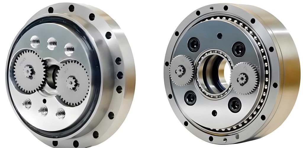
The rotary vector reducer, often abbreviated as RV reducer, is a precision gear mechanism widely used in robotic joints for its high torque capacity, compact size, and low backlash. However, its performance depends on multiple factors, necessitating thorough testing. In my project, I targeted the ZKRV-80E model as the primary measurement object, but the test bed is adaptable for other rotary vector reducer types. The core motivation was to create a platform that not only measures standard parameters but also identifies design weaknesses through comparative analysis with imported counterparts. By leveraging modern automation techniques, this test bed minimizes human error and enhances data processing capabilities, moving beyond traditional manual methods.
To achieve this, I first established the theoretical foundations for the measurements. The rotary vector reducer’s performance is quantified through several indicators: transmission ratio, transmission efficiency, transmission error, transmission accuracy, and torsional stiffness. Each of these requires precise calculation based on input and output data. For instance, the transmission ratio \( i \) is derived from the rotational speeds of the input and output shafts. Let \( n_1 \) be the input speed and \( n_2 \) the output speed; then, the transmission ratio is given by:
$$ i = \frac{n_1}{n_2} $$
This simple formula belies the complexity of ensuring accurate speed measurements under dynamic loads, which my test bed addresses through high-resolution encoders. Similarly, transmission efficiency \( \eta \) is a critical metric for energy loss assessment. It is calculated using the input torque \( T_1 \) and output torque \( T_2 \), along with the transmission ratio:
$$ \eta = \frac{T_2}{i \cdot T_1} \times 100\% $$
In practice, efficiency varies with load and speed, so my design incorporates variable conditions to capture these nuances. The rotary vector reducer’s precision is further evaluated through transmission error \( E \), which represents the deviation between the theoretical and actual output angles. If \( \phi_1 \) is the actual input angle and \( \phi_2 \) the actual output angle, the error is:
$$ E = \frac{\phi_1}{i} – \phi_2 $$
This error arises from manufacturing imperfections and wear, and minimizing it is crucial for robotic accuracy. From the transmission error data, I derive transmission accuracy \( \theta \), defined as the range between maximum and minimum error values in a dataset:
$$ \theta = E_{\text{max}} – E_{\text{min}} $$
A smaller \( \theta \) indicates higher consistency, which is vital for repetitive tasks in robotics. Lastly, torsional stiffness \( K \) measures the rotary vector reducer’s resistance to deformation under load. By locking the output and applying a known torque \( T_1 \) at the input, I measure the input angle \( \theta_1 \) and the output twist angle \( \Delta \theta_2 \). The stiffness is then:
$$ K = \frac{i T_1}{\theta_1 / i – \Delta \theta_2} $$
This parameter is essential for assessing structural integrity, especially in high-load applications. These formulas guided my sensor selection and data acquisition system design, ensuring that all calculations are automated and precise.
With the principles defined, I proceeded to the test bed design, prioritizing modularity, accuracy, and ease of use. The rotary vector reducer test bed adopts a horizontal structure, where the reducer axis is aligned horizontally, and the drive motor is positioned on one side. This layout simplifies alignment and reduces radial load issues, though it requires careful balancing. The base is a cast iron plate measuring 2.5 m × 1.0 m × 0.3 m, providing stability and vibration damping. All components are mounted on linear positioning rails with T-slots, allowing quick disassembly and adjustment for different rotary vector reducer models. This modular approach minimizes downtime and enhances versatility.
The drive system centers on a high-performance spindle motor, selected for its power and controllability. After evaluating various options, I chose a model with an S1 rating of 33 kW and an S6 rating of 52.9 kW, capable of speeds up to 9000 rpm. This motor is coupled with an oil-mist lubrication system and water cooling to prevent overheating during prolonged tests. For loading, I integrated a magnetic powder brake with a capacity of 5000 N·m, simulating realistic operational torques on the rotary vector reducer. The brake is also water-cooled to manage the heat generated during energy dissipation. Couplings between modules use flexible plum blossom types: MJC-30C-GR-7×8 between the motor and input sensor, and MJB-55-RD-10×10 between the reducer and brake, ensuring torque transmission without misalignment issues.
Precision measurement relies on torque-speed sensors and encoders. For the input side, where speeds are high but torques lower, I selected a ZJ-100AG sensor with a range of ±100 N·m. On the output side, to handle the higher torques of the rotary vector reducer, a ZJ-5000A sensor with a ±5000 N·m range is used. Both sensors provide real-time data via analog signals, processed by a central control system. Angular measurements use 64-bit resolution encoders, mounted on both input and output shafts, enabling sub-degree accuracy for error calculations. The entire setup is supported by auxiliary systems: an HL0A-03 oil-air lubrication unit for smooth operation, a CW-5200 industrial chiller for temperature control, and a compressed air system including a V-1.6/8 compressor and a 0.3 m³ tank for pneumatic needs. These elements ensure that environmental factors do not compromise test results.
Control and data acquisition are managed through a HY-3A manual controller, chosen for its simplicity and reliability. Although automated systems were considered, this controller offers cost savings without sacrificing precision. It interfaces with a PC running custom software that logs data from all sensors, calculates performance indicators in real-time, and generates plots. The software implements the formulas mentioned earlier, allowing for instant feedback during tests. For example, when measuring the transmission efficiency of the rotary vector reducer, it continuously computes \( \eta \) and displays trends, helping identify anomalies. The test bed’s operational range is summarized in the table below, highlighting its capabilities for the ZKRV-80E model and similar rotary vector reducers.
| Parameter | Specification |
|---|---|
| Measured Object | Rotary Vector Reducer (e.g., ZKRV-80E) |
| Input Speed Range | 0 to 9000 rpm |
| Loading Torque Range | 0 to 5000 N·m |
| Input Torque Sensor Range | ±100 N·m |
| Output Torque Sensor Range | ±5000 N·m |
| Encoder Resolution | 64 bits |
| Base Platform Dimensions | 2.5 m × 1.0 m × 0.3 m |
| Cooling Method | Water-based for motor and brake |
| Lubrication Method | Oil-air for high-speed components |
The three-dimensional model of the test bed, developed using CAD software, illustrates the compact arrangement of components. The layout proceeds linearly: motor, input sensor, input encoder, rotary vector reducer, output encoder, output sensor, and brake, all aligned on the rail system. This design facilitates easy access for maintenance and reducer replacement. During assembly, I emphasized precision alignment using laser tools to minimize parasitic loads that could skew results. The physical implementation, as shown in the image above, confirms the robustness of the structure, with all modules securely fastened and cables neatly routed to prevent interference.
Testing the rotary vector reducer involves a sequence of procedures to evaluate each performance metric. Starting with the starting torque, I gradually increase the input torque until motion is detected by the encoders. The average starting torque for the ZKRV-80E was found to be 499.945 N·m, indicating the initial resistance within the rotary vector reducer. This value is critical for applications requiring frequent start-stop cycles. Next, the transmission ratio test sets the output speed to 15 rpm under an 800 N·m load. The system records input and output speeds, computing \( i \) in real-time. Over multiple runs, the average ratio was 133.905, closely matching the theoretical value for this rotary vector reducer, with minor deviations due to manufacturing tolerances.
For torsional stiffness, I locked the output shaft and applied cyclic loads from -5000 to 5000 N·m, measuring the angular deflection. The relationship between torque and twist angle is nearly linear, as expected for elastic deformation. Using the formula for \( K \), I derived the stiffness curve, which shows a slight hysteresis due to internal friction in the rotary vector reducer. The data points are summarized in the following table, highlighting the reversible nature of the deformation under load.
| Torque (N·m) | Twist Angle (degrees) |
|---|---|
| -1200 | -2.8 |
| -800 | -1.9 |
| -400 | -0.9 |
| 0 | 0.0 |
| 400 | 0.8 |
| 800 | 1.7 |
| 1200 | 2.6 |
Transmission efficiency was assessed at the rated speed and full load. The input torque \( T_1 \) and output torque \( T_2 \) were sampled at high frequency, and efficiency \( \eta \) was calculated continuously. The average efficiency over the test period was 0.822, or 82.2%, which aligns with industry standards for rotary vector reducers of this class. However, fluctuations were observed due to thermal effects and lubrication variations, underscoring the need for controlled environmental conditions. The real-time efficiency plot demonstrates how the rotary vector reducer performs under sustained operation, with efficiency dipping slightly as temperatures rise.
Transmission error and accuracy require high-resolution angle data. I conducted a slow-rotation test, recording input and output angles over several revolutions. The error \( E \) was computed per the formula, revealing a periodic pattern corresponding to the gear teeth engagement in the rotary vector reducer. The peak-to-peak error, representing transmission accuracy \( \theta \), was within 1 arc-minute, indicating high precision. This level of accuracy is essential for robotic applications where positional repeatability is paramount. All these tests were repeated for consistency, and data was aggregated to form a comprehensive performance profile of the rotary vector reducer.
In comparing domestic and imported rotary vector reducers, my test bed revealed subtle differences in efficiency and stiffness. For instance, some domestic models showed 5-10% lower efficiency under high load, likely due to material or heat treatment variations. The torsional stiffness also varied, affecting the dynamic response in robotic arms. By analyzing these metrics, I identified areas for improvement, such as optimizing gear profiles or enhancing lubrication pathways. The test bed thus serves not only as a quality control tool but also as a research platform for advancing rotary vector reducer technology.
The advantages of this test bed design are manifold. Firstly, its modularity allows testing of various rotary vector reducer types without major reconfiguration. Simply by adjusting the rail positions and couplings, I can accommodate different sizes and mounting interfaces. Secondly, the integration of high-precision sensors and automated data processing reduces human error and speeds up testing cycles. Thirdly, the horizontal layout simplifies alignment and maintenance, making it user-friendly for technicians. Lastly, the use of commercial off-the-shelf components, like the spindle motor and magnetic brake, keeps costs low while ensuring reliability. These features collectively make this test bed a valuable asset for manufacturers and researchers focused on rotary vector reducers.
Looking ahead, there are opportunities for enhancement. Future iterations could incorporate more advanced control systems, such as programmable logic controllers (PLCs) for fully automated test sequences. Additionally, integrating thermal imaging cameras could provide insights into heat distribution within the rotary vector reducer during operation. The data acquisition software could be expanded to include machine learning algorithms for predictive maintenance and performance optimization. Despite these potential upgrades, the current test bed already meets its core objectives, delivering accurate and repeatable measurements for rotary vector reducers.
In conclusion, the development of this comprehensive performance test bed for rotary vector reducers represents a significant step toward domesticating critical robotic components. By enabling detailed evaluation of transmission ratio, efficiency, error, accuracy, and stiffness, it provides a foundation for quality assurance and design innovation. My design philosophy centered on balancing cost, precision, and versatility, resulting in a platform that is both practical and scalable. As the demand for high-performance rotary vector reducers grows, such test beds will play an increasingly vital role in driving technological progress and reducing reliance on imports. Through continued refinement and application, I believe this test bed will contribute to the advancement of robotics and smart manufacturing globally.