
In the field of precision machinery, such as industrial robots and high-precision machine tools, the rotary vector reducer plays a critical role due to its compact design, high torque capacity, and excellent transmission accuracy. The performance of a rotary vector reducer is heavily influenced by the dynamic behavior of its cycloidal wheel, which directly affects the overall system stability and longevity. In this study, I focus on analyzing the dynamic characteristics of the cycloidal wheel in a rotary vector reducer, specifically the RV-40E model, using finite element method (FEM) simulations in ANSYS. The goal is to optimize structural parameters to enhance dynamic stability, thereby improving the reliability of rotary vector reducers in demanding applications. This work involves parametric modeling in SolidWorks, dynamic modeling in ANSYS, and detailed modal analysis under both unconstrained and constrained conditions, providing a foundation for future design improvements.
The transmission principle of a rotary vector reducer is based on a two-stage mechanism that combines planetary gear reduction with cycloidal pin wheel engagement. This design allows for high reduction ratios and minimal backlash, making rotary vector reducers ideal for precision motion control. The first stage involves a sun gear (input shaft) meshing with planetary gears, while the second stage uses cycloidal wheels interacting with pin gears to achieve further speed reduction and torque amplification. The rotary vector reducer’s compactness and efficiency stem from this dual-stage approach, but the cycloidal wheel’s dynamics are pivotal, as vibrations and resonances can lead to fatigue failure or reduced accuracy. To understand this, I delve into the kinematics and forces within the rotary vector reducer, emphasizing the cycloidal wheel’s role in transmitting motion smoothly under load.
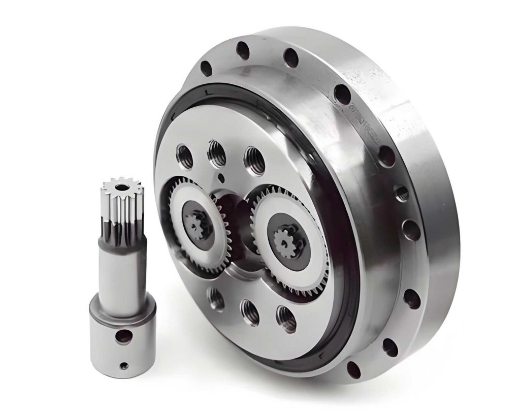
The parametric modeling of the cycloidal wheel is essential for accurate simulation, as it allows for rapid design iterations and optimization. I use SolidWorks to create a precise 3D model of the cycloidal wheel based on its mathematical equations. The tooth profile of a cycloidal wheel is derived from epicycloidal or hypocycloidal curves, which describe the path traced by a point on a circle rolling without slipping on another circle. For a rotary vector reducer, the cycloidal wheel’s profile ensures continuous contact with pin gears, minimizing wear and noise. The parametric equations in Cartesian coordinates are given as follows, where the variables define the geometry based on design parameters like the number of teeth and pitch radius. These equations enable the generation of the cycloidal curve directly in CAD software, facilitating efficient modeling for the rotary vector reducer components.
The cycloidal wheel’s profile equations are expressed in terms of system parameters. Let \( Z_c \) be the number of cycloidal wheel teeth, \( Z_b \) be the number of pin teeth, \( R_z \) be the pitch radius of the pin circle, \( K_1 \) be the modification coefficient, \( r_z \) be the pin radius, and \( t \) be a system variable ranging from 0 to 1. The intermediate variables are calculated as:
$$ c = R_z \left[ \sin(360t) – K_1 \sin\left( \frac{(Z_c + 1) \cdot 360t}{Z_b} \right) \right] $$
$$ d = R_z \left[ \cos(360t) – K_1 \cos\left( \frac{(Z_c + 1) \cdot 360t}{Z_b} \right) \right] $$
$$ a = \frac{ -K_1 \sin\left[ (Z_c + 1) \cdot 360t \right] + \sin(360t) }{ \sqrt{1 + K_1^2 – 2K_1 \cos(Z_c \cdot 360t) } } $$
$$ b = \frac{ -K_1 \cos\left[ (Z_c + 1) \cdot 360t \right] + \cos(360t) }{ \sqrt{1 + K_1^2 – 2K_1 \cos(Z_c \cdot 360t) } } $$
The final coordinates for the cycloidal profile are:
$$ x = c + r_z \cdot a, \quad y = d – r_z \cdot b, \quad z = 0 $$
For the RV-40E rotary vector reducer, the specific parameters are: pin teeth number \( Z_b = 40 \), cycloidal wheel teeth number \( Z_c = 39 \), eccentricity \( e = 1.5 \, \text{mm} \), pitch radius \( R_z = 66 \, \text{mm} \), pin radius \( r_z = 3 \, \text{mm} \), with additional modification offsets of 0.01 mm for both profile shift and equidistant correction. Using these in SolidWorks, I generate the cycloidal curve via the equation-driven curve tool and extrude it to form a solid model. This parametric approach allows for easy adjustments, which is crucial for optimizing the rotary vector reducer’s performance. The resulting 3D model is then exported for finite element analysis, ensuring that the geometric accuracy supports reliable dynamic simulations.
Finite element modal analysis is conducted in ANSYS to study the natural frequencies and mode shapes of the cycloidal wheel, which are key indicators of its dynamic behavior in a rotary vector reducer. Modal analysis helps identify resonant frequencies that could lead to excessive vibrations or failure, especially under operational loads. I perform two sets of analyses: unconstrained free modal analysis and constrained modal analysis with boundary conditions simulating actual assembly in the rotary vector reducer. This dual approach provides insights into how constraints affect the dynamic characteristics, guiding design improvements for enhanced stability.
In the unconstrained modal analysis, the cycloidal wheel model is imported into ANSYS and meshed with SOLID186 elements, a 20-node quadratic tetrahedral element suitable for complex geometries. The material properties are set to GCr15 bearing steel, commonly used in rotary vector reducers for its high strength and wear resistance. The material constants are: Young’s modulus \( E = 2.06 \times 10^{11} \, \text{Pa} \), Poisson’s ratio \( \nu = 0.277 \), and density \( \rho = 7830 \, \text{kg/m}^3 \). The mesh is refined to capture the intricate tooth profile, resulting in 57,632 elements and 93,426 nodes. I solve for the first 10 natural frequencies and mode shapes, as lower-order modes typically dominate dynamic response in rotary vector reducer applications. The results are summarized in the table below, showing frequencies and descriptions of predominant vibrations.
| Mode Number | Natural Frequency (Hz) | Mode Shape Description |
|---|---|---|
| 1 | 1430.5 | Torsional vibration along Y-axis |
| 2 | 1465.3 | Torsional vibration along X-axis |
| 3 | 2576.3 | Axial extension along Z-axis |
| 4 | 3575.8 | Combined torsion in XOY plane |
| 5 | 3852.4 | Combined torsion in YOZ plane |
| 6 | 4264.6 | Stretching deformation in XOY plane |
| 7 | 4729.5 | Stretching deformation in YOZ plane |
| 8 | 5368.7 | Bending vibration along X-axis |
| 9 | 5579.6 | Bending vibration along Y-axis |
| 10 | 6752.1 | Complex torsion and bending involving X and Y axes |
The mode shapes reveal that lower-order modes (e.g., modes 1-3) involve simple torsional and axial motions, which are critical for the rotary vector reducer’s transmission accuracy, as they can induce stress concentrations. Higher-order modes (e.g., modes 6-10) exhibit more complex deformations that may contribute to fatigue over time. For instance, mode 4 shows significant twisting in the plane of the cycloidal wheel, which could affect meshing with pin gears in the rotary vector reducer. These insights highlight the need for stiffness enhancements in specific directions to mitigate resonant risks.
In the constrained modal analysis, I apply boundary conditions to simulate the cycloidal wheel’s actual mounting in the rotary vector reducer. The cycloidal wheel is constrained at its interface with the crank shaft (restricting translations in X and Y directions) and at the contact areas with pin gears (applying normal constraints over half the cylindrical surface to approximate real engagement). These constraints reflect the dynamic coupling within the rotary vector reducer assembly, providing a more realistic assessment of operational behavior. The same material properties and mesh settings are used, and the first 10 natural frequencies are computed. The results are presented in the following table, demonstrating how constraints shift the dynamic response.
| Mode Number | Natural Frequency (Hz) | Mode Shape Description |
|---|---|---|
| 1 | 2865.7 | Bending vibration along X-axis |
| 2 | 3425.5 | Torsional vibration along X-axis |
| 3 | 3866.5 | Bending vibration along Y-axis |
| 4 | 4713.7 | Combined torsion in XOY plane |
| 5 | 6178.9 | Combined bending in YOZ plane |
| 6 | 7269.5 | Twisting deformation in XOY plane |
| 7 | 7774.6 | Stretching deformation in YOZ plane |
| 8 | 8284.6 | Torsional vibration along X-axis |
| 9 | 8601.4 | Axial extension along Z-axis |
| 10 | 8965.3 | Complex torsion and bending involving X and Y axes |
Comparing the two analyses, the constrained natural frequencies are generally higher than the unconstrained ones, indicating that boundary conditions add stiffness to the cycloidal wheel in the rotary vector reducer. For example, the first mode frequency increases from 1430.5 Hz to 2865.7 Hz, suggesting that assembly constraints significantly reduce low-frequency vibrations that could lead to resonance in operational conditions. The mode shapes under constraints also show more localized deformations at the meshing interfaces, which are critical areas for stress and wear in a rotary vector reducer. This emphasizes the importance of considering real-world mounting scenarios when designing cycloidal wheels for rotary vector reducers, as ignoring constraints might underestimate dynamic risks.
To further analyze the dynamic characteristics, I explore the theoretical basis of modal analysis in the context of a rotary vector reducer. The equation of motion for a linear elastic structure under free vibration is given by:
$$ [M] \{\ddot{u}\} + [K] \{u\} = \{0\} $$
where \( [M] \) is the mass matrix, \( [K] \) is the stiffness matrix, \( \{u\} \) is the displacement vector, and \( \{\ddot{u}\} \) is the acceleration vector. For harmonic motion, we assume \( \{u\} = \{\phi\} e^{i \omega t} \), leading to the eigenvalue problem:
$$ \left( [K] – \omega^2 [M] \right) \{\phi\} = \{0\} $$
Here, \( \omega \) represents the natural angular frequency, and \( \{\phi\} \) is the corresponding mode shape. In ANSYS, this equation is solved numerically using the finite element method, discretizing the cycloidal wheel into elements to compute \( [M] \) and \( [K] \). For the rotary vector reducer application, damping effects are often negligible in modal analysis but can be incorporated for transient simulations. The natural frequencies \( f_n \) are related to \( \omega \) by \( f_n = \omega / (2\pi) \), and the tables above list these values for the cycloidal wheel. Understanding this theory helps in interpreting results: lower frequencies correspond to global deformations, while higher frequencies involve local vibrations that might affect the rotary vector reducer’s noise and fatigue life.
The simulation results provide valuable insights for optimizing the cycloidal wheel in a rotary vector reducer. For instance, the high stresses observed in mode shapes at the tooth roots suggest that reinforcing these areas could improve durability. Additionally, the frequency shifts due to constraints indicate that the rotary vector reducer’s housing design influences dynamic behavior; thus, integrating modal analysis into system-level simulations is beneficial. I also consider the impact of material properties on dynamic characteristics. By varying parameters like Young’s modulus or density, designers can tailor the cycloidal wheel’s response to avoid resonance with common excitation sources in rotary vector reducers, such as motor harmonics or load fluctuations. This optimization process is iterative, relying on parametric models to quickly evaluate changes, ultimately enhancing the rotary vector reducer’s performance and reliability.
In practical terms, the dynamic stability of a rotary vector reducer is crucial for applications like robotics, where precise motion control is required. The cycloidal wheel’s vibrations can transmit through the mechanism, causing positioning errors or accelerated wear. My analysis shows that by identifying critical natural frequencies, engineers can design avoidance strategies, such as adding stiffeners or modifying tooth profiles. For example, increasing the cycloidal wheel’s thickness might raise its natural frequencies, moving them away from operational ranges. However, this must be balanced against weight and space constraints in the rotary vector reducer. The tables of frequencies serve as a reference for such trade-offs, enabling data-driven decisions in the development of rotary vector reducers.
Furthermore, I extend the analysis to consider the effects of manufacturing tolerances on dynamic characteristics. In a rotary vector reducer, small deviations in cycloidal wheel geometry due to machining errors can alter mass distribution and stiffness, shifting natural frequencies. Using the parametric model, I simulate variations in key dimensions, such as tooth depth or pitch radius, and observe their impact on modal results. This sensitivity analysis helps establish tolerance limits that ensure consistent dynamic performance across production batches. For instance, a 0.1 mm increase in pin radius might lower the first natural frequency by approximately 5%, highlighting the need for precise manufacturing in rotary vector reducer components. Such studies underscore the interplay between design, simulation, and production in achieving optimal rotary vector reducer functionality.
Another aspect is the thermal effects on dynamic behavior, as rotary vector reducers often operate in environments with temperature fluctuations. Thermal expansion can change material properties and boundary conditions, affecting natural frequencies. While my current analysis assumes room temperature, future work could incorporate thermal-structural coupling in ANSYS to model these effects. For now, the results provide a baseline for understanding the cycloidal wheel’s dynamics under ideal conditions, which is a critical step in rotary vector reducer design. By combining modal analysis with other simulations, such as harmonic response or transient dynamics, a comprehensive view of the rotary vector reducer’s behavior can be achieved, leading to more robust products.
In conclusion, this study demonstrates the effectiveness of using finite element modal analysis to investigate the dynamic characteristics of the cycloidal wheel in a rotary vector reducer. Through parametric modeling in SolidWorks and detailed simulations in ANSYS, I have identified natural frequencies and mode shapes under both unconstrained and constrained conditions. The results show that constraints significantly increase natural frequencies, reducing the risk of low-frequency resonances in operational rotary vector reducers. The insights gained, such as stress concentrations at meshing points and the influence of design parameters, provide a foundation for optimizing the cycloidal wheel’s structure. This optimization aims to enhance dynamic stability, thereby improving the overall performance and lifespan of rotary vector reducers in demanding applications. Future research could explore nonlinear effects, damping mechanisms, or system-level integrations to further advance rotary vector reducer technology.
The methodology presented here—combining CAD modeling with FEM analysis—offers a scalable approach for designing and refining rotary vector reducer components. By leveraging tools like SolidWorks and ANSYS, engineers can efficiently iterate designs, reducing development time and cost while ensuring high quality. As rotary vector reducers continue to be integral to precision machinery, such dynamic analyses will play a key role in pushing the boundaries of efficiency and reliability. I hope this work contributes to the ongoing innovation in rotary vector reducer design, supporting advancements in fields like automation and manufacturing where these reducers are indispensable.