
The rotary vector reducer, a highly precise and compact transmission device, is a cornerstone of modern industrial robotics, aerospace equipment, and high-precision machinery. Its superior characteristics, including a high reduction ratio, substantial load-bearing capacity, compact volume, and excellent transmission efficiency, make it indispensable for applications requiring precise motion control. The conventional design process for a rotary vector reducer involves the meticulous creation of numerous components—often nearly twenty distinct parts such as the cycloid gear, pin housing, crankshaft, and planetary gears. This traditional approach is not only time-consuming and labor-intensive but also prone to human error, significantly hindering rapid product development and iteration to meet dynamic market demands.
To overcome these challenges, parametric design has emerged as a transformative methodology. By defining a three-dimensional model with a set of quantifiable variables and constraints, new component geometries can be generated automatically by simply altering the input parameters. This drastically reduces design cycles, enhances accuracy, and facilitates the exploration of design alternatives. While existing research has made progress in parameterizing specific components like the cycloid gear, a comprehensive, system-level parametric solution for the entire rotary vector reducer assembly remains an area for further development. Furthermore, many existing methods for modeling complex curves, such as gear tooth profiles, rely on spline curve fitting techniques, which can be computationally intensive and less precise.
This article presents the design and implementation of a fully parametric three-dimensional digital modeling system specifically for rotary vector reducers. The system is developed using Visual Basic 6.0 as the programming environment to perform secondary development on the commercial CAD software SolidWorks. The core innovation lies in the creation of an integrated software platform that guides users through an intuitive interface. Designers input drawing data and key parameters via this platform, and the underlying program automatically drives SolidWorks to execute parametric modeling for all critical components of the rotary vector reducer. A particularly efficient technique employed is the direct modification of the involute equation within SolidWorks using its equation-driven curve functionality, bypassing the need for traditional, less accurate spline fitting. The design process rigorously incorporates practical engineering considerations, such as gear profile shifting, grinding allowances for gears, and precise modification of cycloid gear tooth profiles, ensuring the generated models are directly applicable to real-world manufacturing and analysis.
Structural Principle and Working Mechanism of the Rotary Vector Reducer
The rotary vector reducer is essentially a two-stage planetary transmission system that combines a traditional involute gear stage with a cycloidal-pin gear stage. Its compact and highly efficient design is key to its performance. The primary function of the rotary vector reducer is to provide high reduction ratios with minimal backlash and high torque capacity.
The first reduction stage is a standard involute planetary gear train. It consists of a centrally located input sun gear (often integrated onto the input shaft) that meshes with multiple planetary gears. The planetary gears are mounted on a carrier that is part of the second stage’s input mechanism. This stage provides an initial, moderate speed reduction.
The second, and most distinctive, stage is the cycloidal or “RV” stage, which provides the major speed reduction. The planetary gears from the first stage are connected to crankshafts. These crankshafts, serving as the input to the second stage, have an eccentric section. A pair of cycloid gears (or “RV gears”) is mounted on these eccentric portions of the crankshafts. The cycloid gears mesh with a ring of stationary pin teeth housed in the pin housing (or “pin wheel”). As the crankshafts rotate, they impart an eccentric motion to the cycloid gears. The interaction between the lobed profile of the cycloid gears and the stationary pins forces the cycloid gears to undergo a compound motion: they revolve (precess) around the central axis of the pin housing while simultaneously rotating on their own axes. This slow relative rotation of the cycloid gears is then transferred to the output flange or planet carrier, which is connected to the output shaft, resulting in a very high reduction ratio. The use of two cycloid gears phased 180 degrees apart balances inertial forces and improves torque transmission smoothness. The overall reduction ratio $i_{total}$ of the rotary vector reducer is the product of the ratios of the two stages:
$$ i_{total} = i_{stage1} \times i_{stage2} = (1 + \frac{Z_{ring}}{Z_{sun}}) \times (\frac{Z_p}{Z_p – Z_c}) $$
where $Z_{ring}$ is the number of teeth on the stationary ring gear (in a standard planetary first stage), $Z_{sun}$ is the number of teeth on the sun gear, $Z_p$ is the number of pin teeth in the housing, and $Z_c$ is the number of lobes on the cycloid gear. In the common RV configuration where the first stage uses a sun-planet system and the planets drive the crankshafts, the formula adapts, but the two-stage multiplicative principle remains.
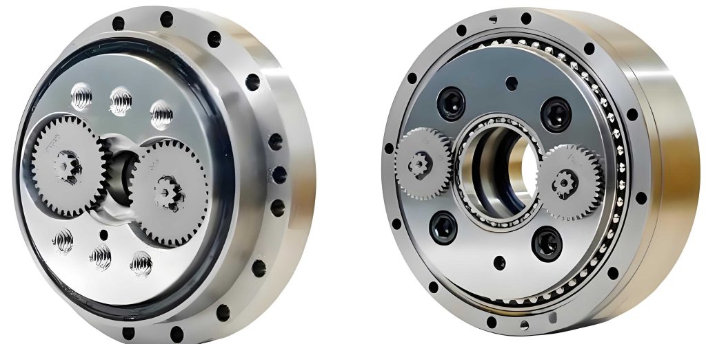
Methodology for Parametric Design and System Development
The successful implementation of a parametric design system for a complex assembly like the rotary vector reducer requires a structured methodology, leveraging appropriate software tools and development strategies.
SolidWorks Secondary Development Approaches
SolidWorks provides a robust Application Programming Interface (API) that allows users to automate and extend its functionality. Three primary methods are commonly used for secondary development in the context of parametric design for components like those in a rotary vector reducer:
| Method | Description | Advantages | Disadvantages | Suitability for RV Reducer |
|---|---|---|---|---|
| Full Programming | Writing complete code to define every feature and sketch from scratch. | Maximum control and flexibility; no pre-existing model required. | High programming complexity and effort; lengthy code. | Ideal for complex, equation-driven parts like the cycloid gear. |
| Macro Recording | Using SolidWorks to record manual actions and generate corresponding VBA code. | Quick start; reduces initial programming effort by providing code snippets. | Generated code can be verbose and unstructured; may require significant cleanup. | Useful as an aid to understand API calls for specific operations. |
| Dimension Driving | Creating a template model and programmatically modifying its defined dimensions/parameters. | Low programming overhead; fast model regeneration; intuitive. | Requires a well-defined, fully constrained template model. | Excellent for standardized parts like housings, shafts, flanges, and standard gears. |
For the comprehensive parametric design system of the rotary vector reducer, a hybrid approach is optimal. The cycloid gear, with its complex, mathematically defined tooth profile, is best suited for the Full Programming method. All other major components, such as the input gear shaft, pin housing, planetary gears, and crankshafts, can be efficiently modeled using the Dimension Driving method, with Macro Recording used as a supplementary tool to decipher specific API commands.
Development Tools and Workflow
Visual Basic 6.0 (VB6) was selected as the primary development tool due to its simplicity, strong support for COM (Component Object Model) automation—which is how SolidWorks exposes its API—and its rapid application development (RAD) capabilities for creating user-friendly interfaces. The general workflow for parametric design using VB6 to drive SolidWorks is as follows:
- Variable and Interface Definition: Define global variables corresponding to the key design parameters of the rotary vector reducer (e.g., module, number of teeth, eccentricity, diameters). Design the graphical user interface (GUI) forms for user input.
- SolidWorks Connection: Establish a programmatic link to a running instance of SolidWorks using its API objects (e.g., SldWorks, ModelDoc2).
- Parameter Assignment: Retrieve user-input values from the GUI and assign them to the predefined variables.
- Model Generation: Execute one of two paths based on the component:
- Dimension Driving: Open a pre-saved template part file for the component. Programmatically select and modify its named dimensions (e.g.,
"D1@Sketch1") using the assigned variable values. Rebuild the model to update its geometry. - Full Programming: For the cycloid gear, use API methods to create a new part, construct sketches point-by-point based on the cycloidal equation, and build features (extrudes, cuts, patterns) entirely through code.
- Dimension Driving: Open a pre-saved template part file for the component. Programmatically select and modify its named dimensions (e.g.,
- Model Presentation: Save the newly generated model and orient the SolidWorks view for user inspection.
The design work for the parametric system is logically divided into three core modules corresponding to the reducer’s structure: First Stage Transmission (involute gears), Second Stage Transmission (cycloidal drive components), and Auxiliary Components (bearings, seals, housing, fasteners).
User Interface Design Principles
To ensure an efficient and intuitive design experience, the interactive platform adheres to key interface design principles. Each component’s design dialog is structured into four coherent sections:
- Parameter Input Area: A clearly labeled set of text boxes, drop-down menus, or spin controls where the user enters or modifies the design parameters for the specific rotary vector reducer component.
- Action Control: Prominent command buttons, such as “Create Model” or “Update,” which trigger the parameter processing and SolidWorks automation routines.
- 3D Visual Reference: An embedded or linked image or lightweight 3D view of the component, providing immediate visual context for the parameters being edited.
- 2D Schematic Diagram: A simplified 2D drawing or sketch of the component, often with alphanumeric callouts (e.g.,
da,L1,D2) that directly correspond to the parameter input labels, bridging the gap between traditional drawing interpretation and digital parameter input.
Parametric Design Implementation for Key Components
The practical application of the methodology is demonstrated through the detailed parametric design of two critical and geometrically distinct components of the rotary vector reducer: the input gear shaft (representing dimension-driven design for standardized features) and the cycloid gear (representing full-programming design for complex profiles).
Input Gear Shaft Parametric Modeling
The input shaft of a rotary vector reducer typically integrates a sun gear with a multi-stage shaft. Its parametric design encapsulates both gear generation and shaft profiling.
Parameter Determination: The gear portion requires standard parameters: module ($m$), number of teeth ($z$), pressure angle ($\alpha$), profile shift coefficient ($x$), face width ($b$), along with manufacturing-corrected addendum ($d_a$) and dedendum ($d_f$) diameters. The shaft portion requires diameters and lengths for each segment, as well as dimensions for keyways, holes, and chamfers. A representative set of input gear shaft parameters is shown below.
| Parameter Symbol | Description | Example Value |
|---|---|---|
| $m$ | Module | 1.5 mm |
| $z$ | Number of Teeth | 12 |
| $\alpha$ | Pressure Angle | 20° |
| $x$ | Profile Shift Coefficient | +0.548 |
| $d_a$ | Addendum Diameter (corrected) | 22.3 mm |
| $d_f$ | Dedendum Diameter (corrected) | 15.89 mm |
| $b$ | Face Width | 10 mm |
| $L_1, L_2, L_3$ | Shaft Segment Lengths | Varies |
| $D_1, D_2, D_3$ | Shaft Segment Diameters | Varies |
Modeling Strategy and Equations: The involute tooth profile is generated using SolidWorks’ “Equation Driven Curve” tool. The parametric equations for an involute curve in the Cartesian plane, relative to the gear’s base circle radius $r_b = \frac{m z \cos\alpha}{2}$, are:
$$ x(t) = r_b (\sin u(t) – u(t) \cos u(t)) $$
$$ y(t) = r_b (\cos u(t) + u(t) \sin u(t)) $$
where $u(t)$ is a parametric variable representing the roll angle, typically varying from the start to the end of the involute active profile. For a profile-shifted gear, the angular position of the tooth profile on the pitch circle must be adjusted to maintain correct tooth thickness. The half-tooth-space angle $\gamma$ on the pitch circle, used to position the involute segment correctly in the sketch, is calculated as:
$$ \gamma = \frac{\pi}{2z} – \frac{2x \tan\alpha}{z} $$
This angle ensures the tooth thickness $s$ on the pitch circle is $s = m(\frac{\pi}{2} + 2x \tan\alpha)$.
Parametric Program Implementation: The VB6 code for the input shaft follows the dimension-driving method. A template part contains fully defined sketches and features. The core of the program involves connecting to SolidWorks, opening this template, and systematically changing its named dimensions.
' Example Code Snippet for Dimension Driving
Dim swApp As SldWorks.SldWorks
Dim swModel As ModelDoc2
Set swApp = CreateObject("SldWorks.Application") ' Connect to SolidWorks
Set swModel = swApp.OpenDoc6("C:\Templates\InputShaft.SLDPRT", 1, 0, "", 0, 0)

' Assign user-input values to template parameters
swModel.Parameter("D1@Sketch-Addendum").SystemValue = rv_da / 1000 ' Convert to meters
swModel.Parameter("D1@Boss-Extrude1").SystemValue = rv_b / 1000
swModel.Parameter("D2@Sketch-ShaftDia").SystemValue = rv_D2 / 1000
swModel.Rebuild3 ' Regenerate the model with new dimensions
For the equation-driven involute curve, a different API call is required to edit the equation string itself:
' Selecting and modifying the equation-driven curve
swModel.Extension.SelectByID2 "SketchGearProfile", "SKETCH", 0, 0, 0, False, 0, Nothing, 0
swModel.EditSketch
swModel.Extension.SelectByID2 "Curve1", "SKETCHSEGMENT", 0, 0, 0, False, 0, Nothing, 0
Dim eqCurve As EquationDriveCurve
Set eqCurve = swModel.SelectionManager.GetSelectedObject6(1, -1)
' Update the equation with the current base diameter (rv_Db) variable
eqCurve.SetEquation2 "rv_Db/2*(cos(t)+t*sin(t))", "rv_Db/2*(sin(t)-t*cos(t))", "", 0, 3.1416/2, 1, 0, 2, 2, True, True
The final interface for the input gear shaft parametric design integrates input fields for all parameters, action buttons, and visual guides, enabling rapid regeneration of the shaft model tailored to any specific rotary vector reducer design.
Cycloid Gear Parametric Modeling
The cycloid gear is the heart of the rotary vector reducer’s second stage. Its tooth profile is mathematically complex and often requires precise modification (or “correction”) to optimize performance, reduce wear, and compensate for manufacturing tolerances.
Parameter Determination and Profile Equations: The shape of a standard cycloid gear tooth is derived from the trajectory of a point on a rolling circle (generating circle) relative to a fixed base circle (pin circle). For a rotary vector reducer, the gear has one fewer lobe ($Z_c$) than there are pins ($Z_p$) in the housing ($Z_p – Z_c = 1$). Key parameters include the number of gear lobes ($Z_c$), number of pins ($Z_p$), eccentricity ($a$), pin center circle radius ($R_p$ or $r_p$), pin radius ($R_{rp}$ or $r_{rp}$), and gear thickness. Crucially, practical designs employ profile modifications, primarily “offset modification” ($\Delta R_p$ or $drp$) and “equidistant modification” ($\Delta R_{rp}$ or $drrp$). The modified tooth profile coordinates are given by the following set of equations, which form the basis for the full programming method:
Let $i_H = \frac{Z_c}{Z_p}$ be the transmission ratio of the cycloid stage. For a parameter $t$ representing the rolling angle (from $0$ to $2\pi$), first calculate an intermediate term:
$$ S_r = 1 + K_1^2 – 2 K_1 \cos(t) $$
where $K_1 = \frac{R_p}{a} \cdot \frac{Z_c}{Z_p}$ is the short width coefficient. Then, the coordinates $(X, Y)$ of a point on the modified cycloid profile are:
$$ X = \left( (R_p + \Delta R_p) – \frac{(R_{rp} + \Delta R_{rp})}{\sqrt{S_r}} \right) \cos\left((1 – i_H)t\right) – \frac{a}{R_p + \Delta R_p} \left( R_p + \Delta R_p – Z_c \frac{(R_{rp} + \Delta R_{rp})}{\sqrt{S_r}} \right) \cos\left(i_H t\right) $$
$$ Y = \left( (R_p + \Delta R_p) – \frac{(R_{rp} + \Delta R_{rp})}{\sqrt{S_r}} \right) \sin\left((1 – i_H)t\right) + \frac{a}{R_p + \Delta R_p} \left( R_p + \Delta R_p – Z_c \frac{(R_{rp} + \Delta R_{rp})}{\sqrt{S_r}} \right) \sin\left(i_H t\right) $$
| Parameter | Symbol | Example Value |
|---|---|---|
| Cycloid Gear Lobes | $Z_c$ | 39 |
| Pin Number | $Z_p$ | 40 |
| Eccentricity | $a$ | 1.0 mm |
| Pin Center Circle Radius | $R_p$ | 103 mm |
| Pin Radius | $R_{rp}$ | 5 mm |
| Offset Modification | $\Delta R_p$ | +0.027 mm |
| Equidistant Modification | $\Delta R_{rp}$ | -0.022 mm |
| Gear Thickness | $d$ | 10.5 mm |
Full Programming Implementation: Unlike the dimension-driving approach, the cycloid gear model is built entirely from code. The VB6 program performs the following steps:
- Creates a new SolidWorks part document.
- For discrete values of $t$, calculates the $(X, Y, 0)$ coordinates using the equations above.
- Uses the SolidWorks API method
InsertCurveFilePointor creates a sketch and adds points to it programmatically to define the profile. - Fits a spline through these calculated points to form a smooth, continuous tooth lobe profile.
- Uses this spline to create a closed sketch, which is then extruded to form a single tooth lobe solid.
- Applies a circular pattern feature around the central axis, replicating the lobe $Z_c$ times to complete the full gear.
- Adds other features like the central hub, crankshaft mounting holes, and lightening holes through additional sketches and extrusions/cuts.
' Simplified code structure for generating cycloid points
Dim t As Double
Dim X As Double, Y As Double
Dim swModel As ModelDoc2
' ... (Code to connect to SolidWorks and create a new part) ...
swModel.Insert3DSketch2 True
For t = 0 To Zc * 2 * 3.1415926 Step 0.01 ' Iterate through rolling angle
    ' Calculate Sr, X, Y using the formulas above with current parameters
    Sr = 1 + (K1) ^ 2 - 2 * (K1) * Cos(t)
    X = (Rp + drp - (Rrp + drrp) / Sqr(Sr)) * Cos((1 - iH) * t) - (a / (Rp + drp)) * (Rp + drp - Zc * (Rrp + drrp) / Sqr(Sr)) * Cos(iH * t)
    Y = (Rp + drp - (Rrp + drrp) / Sqr(Sr)) * Sin((1 - iH) * t) + (a / (Rp + drp)) * (Rp + drp - Zc * (Rrp + drrp) / Sqr(Sr)) * Sin(iH * t)
    ' Add the calculated point to the sketch
    swModel.CreatePoint2 X / 1000, Y / 1000, 0 ' Convert mm to meters
Next t
swModel.InsertCurveSpline ' Fit spline through the points
' ... (Code to close sketch, extrude, pattern, etc.) ...
The interface for the cycloid gear design allows the input of all geometric and modification parameters, providing engineers with direct control over the most critical profile of the rotary vector reducer.
Integration into a Unified Parametric Design System Platform
The ultimate objective is not merely to create isolated parametric scripts but to deliver a cohesive, user-friendly software application—a fully parametric 3D digital modeling system for the entire rotary vector reducer. This involves integrating all individual component design modules into a single platform.
The system features a main launch interface that presents the user with a structured menu or graphical layout of all major rotary vector reducer components: Input Shaft & Sun Gear, Planetary Gears, Crankshafts, Cycloid Gears (RV Gears), Pin Housing, Output Flange/Carrier, and Main Housing. Selecting any component opens its dedicated parametric design dialog, built according to the interface principles outlined earlier.
To manage the large number of parameters and components efficiently within the development environment’s constraints, a hierarchical form structure is employed. The main form hosts the interfaces for the most complex and frequently modified primary parts. A secondary form, accessible via a button (e.g., “Auxiliary Parts”), utilizes a tabbed control (like the SSTab control in VB6) to organize the interfaces for standardized parts such as bearings, seals, retaining rings, bolts, and spacers. This keeps the main interface clean while providing comprehensive access to every part needed to assemble a complete virtual prototype of the rotary vector reducer.
The platform’s workflow is streamlined: the user navigates to a component, inputs or modifies parameters based on a new design specification, and clicks “Generate.” The system runs the corresponding VB6 code module, which in turn automates SolidWorks in the background. Within seconds, a new, correctly sized 3D model of the component is created and displayed. This process is repeated for all components. Finally, an automated assembly routine (which can also be parameterized) can be invoked to bring all the generated parts together, creating a complete digital twin of the specified rotary vector reducer design. This integrated system dramatically shortens the design cycle, reduces errors associated with manual modeling, and empowers engineers to perform rapid feasibility studies, design optimizations, and generation of manufacturing drawings directly from the parameter set.
Conclusion
This article has detailed the design and development of a comprehensive, fully parametric three-dimensional digital modeling system for rotary vector reducers. By leveraging the secondary development capabilities of SolidWorks through the Visual Basic 6.0 programming environment, a specialized software platform was constructed. This platform unifies the parametric design of all critical components of the rotary vector reducer, from the first-stage involute gears to the second-stage cycloid drive elements and auxiliary parts. The adoption of a hybrid modeling strategy—employing efficient dimension-driving for standard features and robust full programming for complex, equation-defined profiles like the modified cycloid tooth—ensures both accuracy and computational efficiency. A significant technical advancement is the direct application and programmatic modification of the involute equation within SolidWorks, offering a more precise and elegant solution compared to conventional spline-fitting methods for gear generation.
The system meticulously incorporates essential engineering refinements such as gear profile shifting, manufacturing allowances, and cycloid profile modifications, ensuring the generated digital models are not merely theoretical but are directly relevant and applicable to practical engineering design, analysis (e.g., FEA), and manufacturing preparation. The intuitive, visually-guided user interface lowers the barrier to entry, allowing designers to focus on design intent rather than software mechanics. In summary, this parametric design system represents a powerful tool that can significantly accelerate the research, development, and customization processes for rotary vector reducers, contributing to faster innovation cycles in robotics and precision machinery industries.