
In the field of precision machinery, particularly in industrial robotics, the RV reducer plays a critical role due to its high reduction ratio, compact structure, and low transmission error. As a key component in robot joints, the performance of the RV reducer directly affects the accuracy and stability of robotic systems. However, the main bearings in RV reducers are often thin-walled and susceptible to significant deformation under operational loads, which can introduce transmission errors that compromise overall system precision. In this analysis, I explore how the flexible characteristics and lubrication properties of main bearings influence the transmission error of RV reducers, aiming to provide insights for design optimization and enhanced performance.
The RV reducer is a two-stage transmission device combining planetary gear drives and cycloidal pin-wheel mechanisms. Its compact design allows for high torque transmission with minimal backlash, but the inherent flexibility of thin-walled main bearings poses challenges. These bearings, typically angular contact ball bearings, support the output shaft and endure combined axial and radial loads. When deformation occurs in the bearing rings, it alters the contact dynamics within the bearing and propagates through the reducer, affecting the kinematic accuracy. Additionally, lubrication conditions, such as oil film thickness and pressure, further modulate these interactions. Therefore, a comprehensive study integrating bearing flexibility and lubrication is essential for understanding and mitigating transmission errors in RV reducers.
To address this, I developed a multi-faceted modeling approach. First, I constructed parametric three-dimensional models of the main bearing and the RV reducer using CAD software. The main bearing was designed as an angular contact ball bearing with non-standard dimensions tailored for RV reducer applications. Key parameters are summarized in the following table to establish a foundation for subsequent analyses.
| Parameter | Value |
|---|---|
| Inner Ring Diameter (mm) | 260 |
| Outer Ring Diameter (mm) | 360 |
| Ball Diameter (mm) | 30 |
| Pitch Circle Diameter (mm) | 310 |
| Number of Balls | 26 |
| Contact Angle (degrees) | 40 |
The RV reducer model incorporates a two-stage transmission system. The first stage involves involute planetary gears, and the second stage consists of cycloidal drives. The technical specifications are crucial for dynamic simulations, as shown below.
| Parameter | Value |
|---|---|
| Sun Gear Teeth (z1) | 12 |
| Planet Gear Teeth (z2) | 44 |
| Cycloid Gear Teeth (zc) | 59 |
| Pin Gear Teeth (zrp) | 60 |
| Module (mm) | 3 |
| Pressure Angle (degrees) | 20 |
| Eccentricity (a, mm) | 2.4 |
| Planet Gear Width (b2, mm) | 16 |
| Pin Diameter (drp, mm) | 10 |
| Pin Center Circle Diameter (dp, mm) | 165 |
With these models, I proceeded to develop a rigid-flexible coupled multi-body dynamics model for the main bearing. Using finite element analysis, I converted the bearing rings into flexible bodies to account for deformation under load. The modal neutral files were imported into dynamics simulation software, where contact forces between balls and rings were defined using Hertzian contact theory with an Impact function. The contact force \( F \) between components is expressed as:
$$ F = \begin{cases}
0, & \text{if } p > p_1 \\
k(p_1 – p)^e – c_{\text{max}} \dot{p} \cdot \text{step}(p, p_1 – d, 1, p_1, 0), & \text{if } p \leq p_1
\end{cases} $$
where \( p \) is the measured displacement, \( p_1 \) is the displacement threshold, \( k \) is the stiffness coefficient, \( e \) is the exponent, \( c_{\text{max}} \) is the damping coefficient, and \( \dot{p} \) is the velocity. This formulation allows for realistic simulation of bearing dynamics, including transient and steady-state behaviors.
Next, I integrated an elastohydrodynamic lubrication (EHL) model that considers ring deformation. The Reynolds equation governs the lubrication film between balls and rings:
$$ \frac{\partial}{\partial x} \left( \frac{\rho h^3}{\eta} \frac{\partial p}{\partial x} \right) + \frac{\partial}{\partial y} \left( \frac{\rho h^3}{\eta} \frac{\partial p}{\partial y} \right) = 12 u_s \frac{d(\rho h)}{dx} $$
Here, \( p \) is the oil film pressure, \( h \) is the film thickness, \( \rho \) is the density, \( \eta \) is the viscosity, and \( u_s \) is the entrainment velocity. The density and viscosity vary with pressure according to:
$$ \rho = \rho_0 \left( 1 + \frac{0.6p}{1 + 1.7p} \right) $$
$$ \eta = \eta_0 \exp \left\{ (\ln \eta_0 + 9.67) \left[ \left( 1 + \frac{p}{p_0} \right)^z – 1 \right] \right\} $$
where \( \rho_0 \) and \( \eta_0 \) are initial values, \( p_0 \) is a pressure coefficient, and \( z \) is set to 0.68. The film thickness equation incorporates deformation effects:
$$ h(x, y) = h_0 + \frac{x^2}{2R_x} + \frac{y^2}{2R_y} + \frac{2}{\pi E} \iint_\Omega \frac{p(s, t)}{\sqrt{(x – s)^2 + (y – t)^2}} \, ds \, dt $$
with \( h_0 \) as the initial gap, \( R_x \) and \( R_y \) as equivalent radii, and \( E \) as the elastic modulus. To solve these equations, I implemented a user subroutine that couples lubrication dynamics with the multi-body model, enabling iterative computation of film thickness, pressure, and deformation.
For the RV reducer dynamics, I derived meshing stiffness and damping for both transmission stages. The meshing stiffness of involute gears was calculated based on ISO standards. The single tooth stiffness \( c’ \) is given by:
$$ c’ = \frac{1}{q} $$
where \( q \) is the compliance per unit width, computed as:
$$ q = 0.04723 + \frac{0.15551}{z_1} + \frac{0.25791}{z_2} – 0.00635x_1 – \frac{0.11654 x_1}{z_1} – 0.00193x_2 – \frac{0.24188 x_2}{z_2} + 0.00529x_1^2 + 0.00182x_2^2 $$
Here, \( x_1 = 0.5 \) and \( x_2 = -0.5 \) for the sun and planet gears. The meshing stiffness \( k_{12} \) for the gear pair is then:
$$ k_{12} = c_r b \times 10^6 \, \text{N/m} $$
with \( c_r = (0.75 \varepsilon_a + 0.25) c’ \), where \( \varepsilon_a \) is the contact ratio. The damping \( c_{12} \) is:
$$ c_{12} = 2 \xi_{12} \sqrt{ \frac{k_{12} r_1^2 r_2^2 J_1 J_2}{r_1^2 J_1 + r_2^2 J_2} } $$
where \( \xi_{12} \) is the damping ratio, \( r_1 \) and \( r_2 \) are pitch radii, and \( J_1 \) and \( J_2 \) are moments of inertia.
For the cycloidal stage, the stiffness \( k_{ni} \) for each pin is:
$$ k_{ni} = \frac{\pi b E \rho_r \rho_c}{4(1 – \mu^2)(\rho_r + \rho_c) \rho_i} $$
with curvatures \( \rho_r \), \( \rho_c \), and \( \rho_i \) defined based on geometric parameters. The overall meshing stiffness \( k_{34} \) sums contributions from all engaged pins:
$$ k_{34} = \sum_{i=m}^{n} k_{ni} l_i^2 $$
where \( l_i \) is the distance from the contact normal to the cycloid center. Damping \( c_{34} \) is similarly computed using a damping ratio \( \xi_{34} \). These parameters were incorporated into a full dynamics model of the RV reducer, which includes the main bearings as flexible components.
The assembled RV reducer model simulates operational conditions with an input speed of 9000 °/s and a load torque of 20 N·m. The transmission ratio \( i \) of the RV reducer is theoretically:
$$ i = 1 + \frac{z_2 z_{rp}}{z_1 (z_{rp} – z_c)} $$
which yields approximately 221 for the given parameters. To validate the model, I compared simulated speeds with theoretical values. The results confirmed accuracy, as shown in the table below, establishing a reliable basis for further analysis.
| Parameter | Simulation Value | Theoretical Value |
|---|---|---|
| Input Speed (°/s) | 9000 | 9000 |
| Planet Gear Speed (°/s) | 2452.0 | 2452.3 |
| Output Speed (°/s) | 40.72 | 40.70 |
| Total Transmission Ratio | 221.02 | 221.00 |
Dynamic responses of key components were analyzed. The crank shaft and cycloid gear exhibit sinusoidal displacement curves due to their orbital motions, with amplitudes corresponding to eccentricities. These motions are fundamental to the operation of the RV reducer and influence load distribution. The main bearing contact forces were evaluated during startup and steady-state phases. In startup, contact forces remained below 200 N, indicating smooth engagement. During steady operation, forces varied periodically with a mean of 93.7 N, reflecting combined axial and radial loads.
Transmission error \( \Delta E \) is a critical metric, defined as:
$$ \Delta E = \theta_{\text{out}} – \frac{\theta_{\text{in}}}{i} $$
where \( \theta_{\text{out}} \) and \( \theta_{\text{in}} \) are output and input angles, respectively. I computed transmission errors for two scenarios: a fully rigid model and a model with flexible main bearings. The results highlight the impact of bearing flexibility. In the rigid model, transmission error ranged from -25.2″ to 21.6″ with a period of 0.15 s. When bearing flexibility was included, the error range expanded to -43.2″ to 45″ with a period of 0.28 s. This demonstrates that neglecting flexible characteristics in main bearings can lead to underestimation of transmission errors in RV reducers.
To delve deeper, I investigated how specific factors affect transmission error. First, ring deformation was analyzed under varying loads. As axial and radial loads increase, the elastic deformation of the bearing rings grows, which propagates through the reducer structure. The table below summarizes deformation values for different load cases.
| Axial Load (kN) | Radial Load (kN) | Elastic Deformation (μm) |
|---|---|---|
| 15 | 20 | 0.35 |
| 20 | 25 | 0.50 |
| 25 | 30 | 0.65 |
Correspondingly, transmission error increases with deformation, emphasizing the need for adequate bearing stiffness in RV reducer designs. Second, lubrication effects were examined by varying oil film thickness and pressure. The film thickness at the maximum load contact point was set to different values, and transmission errors were computed. As thickness increases, error initially decreases then rises, indicating an optimal range for lubrication. Similarly, for oil film pressure, error shows a non-monotonic trend. These relationships are quantified below.
| Minimum Film Thickness (mm) | Peak Pressure (GPa) | Transmission Error Range (arcseconds) |
|---|---|---|
| 0.01 | 0.98 | -40.5 to 42.3 |
| 0.07 | 1.13 | -38.1 to 39.8 |
| 0.18 | 1.25 | -41.7 to 43.5 |
The non-linear behavior suggests that both insufficient and excessive lubrication can degrade performance in RV reducers. Optimizing parameters like bearing clearance and surface roughness is crucial to maintain film thickness and pressure within desirable bounds.
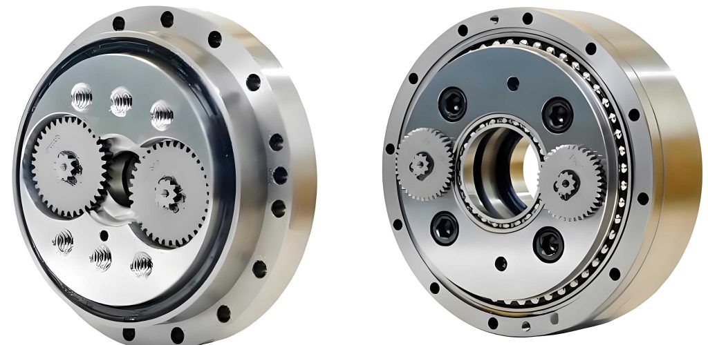
The integration of flexible bearing dynamics and lubrication models provides a holistic view of RV reducer behavior. For instance, deformation alters contact angles and load distribution, which in turn affects lubrication film formation. This coupling is essential for accurate prediction of transmission errors. To visualize the complex structure of an RV reducer, consider the following illustration, which highlights its compact design and internal components.
In practical applications, such as industrial robots, the findings imply that RV reducer designs should prioritize main bearing stiffness while ensuring proper lubrication. For example, using materials with higher modulus or optimized ring geometries can reduce deformation. Additionally, lubrication systems should be tailored to maintain film parameters that minimize error. From a modeling perspective, the multi-body approach with flexible and lubrication coupling offers a powerful tool for virtual prototyping, enabling designers to test various configurations without physical trials.
To further explore the sensitivity of transmission error, I conducted parametric studies on additional factors. For example, variations in bearing preload or alignment errors can exacerbate flexibility effects. Similarly, temperature changes influence lubricant viscosity and thus film characteristics. These aspects warrant future research to enhance RV reducer reliability. Moreover, the methods developed here can be extended to other precision reducers, such as harmonic drives, where flexible components also play a key role.
In conclusion, this analysis underscores the significant impact of main bearing flexibility and lubrication on transmission error in RV reducers. Through integrated modeling and simulation, I demonstrated that bearing ring deformation enlarges error ranges, while lubrication conditions exhibit optimal thresholds. These insights guide design improvements, such as increasing bearing stiffness and optimizing lubrication, to achieve higher precision in RV reducers. The methodologies presented also serve as a reference for advanced reducer development, contributing to the evolution of high-performance robotic systems.
Future work could involve experimental validation using physical RV reducer prototypes, incorporating sensors to measure deformation and error directly. Additionally, machine learning techniques might be applied to optimize design parameters efficiently. As robotics continue to advance, the demand for accurate RV reducers will grow, making such studies increasingly valuable for innovation in the field.