
As a researcher in the field of precision mechanical systems, I have always been fascinated by the challenges and opportunities presented by high-performance reducers. In this study, I focus on the RV reducer, a critical component in applications such as robotics, aerospace, and industrial machinery. The RV reducer is renowned for its high transmission ratio, compact size, excellent efficiency, and superior load-bearing capacity. However, its performance heavily relies on the optimization of the cycloidal gear, which is the core of its secondary transmission stage. Specifically, tooth profile modification of the cycloidal gear is essential to ensure high transmission accuracy, operational stability, and durability. In this work, I aim to explore optimal modification methods and values using a combination of neural networks and genetic algorithms, addressing dynamic factors often overlooked in static models.
The RV reducer operates under loaded conditions, where dynamic interactions such as meshing impacts between the cycloidal gear and pin wheel, as well as coupling effects with double eccentric shafts, significantly influence transmission characteristics. Traditional static optimization approaches may yield results that deviate from real-world performance. Therefore, I developed a dynamic model of the RV reducer under load for various cycloidal gear modification schemes. Through simulation, I extracted output rotation angles and speeds to evaluate transmission accuracy and operational stability. Transmission accuracy was defined as the difference between maximum and minimum transmission errors, while stability was quantified using the variance of output speed after stabilization. To establish a mapping between modification values and these performance metrics, I employed a neural network for prediction. Subsequently, I used a genetic algorithm to optimize the modification values by minimizing a weighted sum of transmission accuracy and stability. Finally, I calculated the maximum meshing force and number of simultaneously engaged teeth for the optimal modification schemes to assess load distribution and carrying capacity. This integrated approach provides a comprehensive framework for enhancing RV reducer performance, balancing precision, stability, and strength.
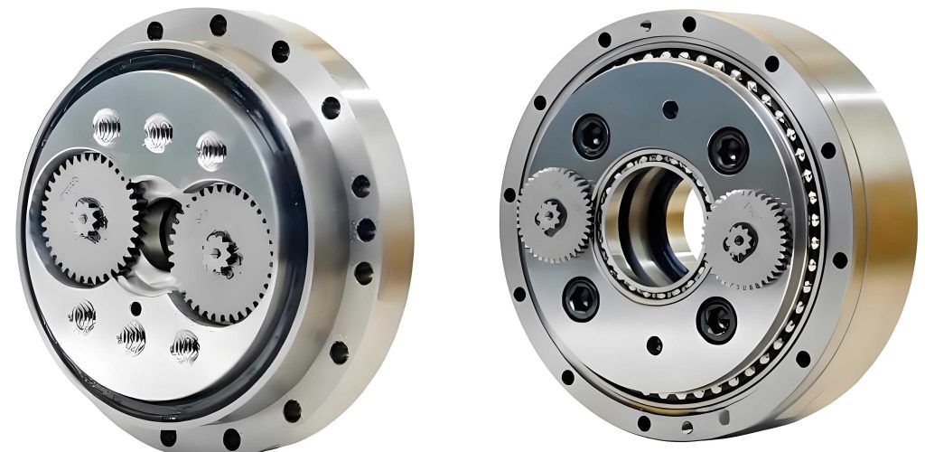
The RV reducer’s excellence stems from its unique design, which includes a cycloidal-pin gear mechanism. This mechanism involves a cycloidal gear meshing with a pin wheel, where the gear’s tooth profile is derived from a hypocycloidal curve. Under ideal conditions, the cycloidal gear should have perfect conjugate action with the pin wheel. However, manufacturing imperfections, elastic deformations under load, and thermal effects necessitate tooth profile modifications to compensate for errors and ensure smooth operation. Common modification methods include equidistant modification and moved distance modification. Equidistant modification involves altering the grinding wheel radius during machining, while moved distance modification adjusts the pin wheel center circle radius. These modifications are typically combined to achieve desired performance improvements. In this study, I considered three combination schemes: positive moved distance with positive equidistance, positive moved distance with negative equidistance, and negative moved distance with positive equidistance. Each scheme has specific constraints to maintain positive backlash and meet backlash requirements, which are crucial for the RV reducer’s functionality.
To derive the modified tooth profile, I started with the theoretical equation of the cycloidal gear. The modified tooth profile equation incorporating both moved distance and equidistant modifications is given by:
$$ x’_c = \left[ r_p – \Delta r_p – (r_{rp} + \Delta r_{rp}) S^{-\frac{1}{2}} \right] \sin\left( (1 – i_H) \phi \right) + \frac{a}{r_p – \Delta r_p} \left[ r_p – \Delta r_p – z_p (r_{rp} + \Delta r_{rp}) S^{-\frac{1}{2}} \right] \sin i_H \phi $$
$$ y’_c = \left[ r_p – \Delta r_p – (r_{rp} + \Delta r_{rp}) S^{-\frac{1}{2}} \right] \cos\left( (1 – i_H) \phi \right) – \frac{a}{r_p – \Delta r_p} \left[ r_p – \Delta r_p – z_p (r_{rp} + \Delta r_{rp}) S^{-\frac{1}{2}} \right] \cos i_H \phi $$
where \( r_p \) is the pin wheel center circle radius, \( r_{rp} \) is the pin radius, \( \Delta r_p \) is the moved distance modification value, \( \Delta r_{rp} \) is the equidistant modification value, \( i_H \) is the transmission ratio between the cycloidal gear and pin wheel, \( z_p \) is the number of pin teeth, \( a \) is the eccentric distance, \( \phi \) is the position angle, and \( S = 1 + k’_1^2 – 2k’_1 \cos \phi \) with \( k’_1 = a z_p / (r_p – \Delta r_p) \). By varying \( \Delta r_p \) and \( \Delta r_{rp} \), I generated different tooth profiles for simulation and analysis.
For dynamic simulation, I built a virtual prototype of the RV reducer using ADAMS software. The model included key components such as the cycloidal gear, pin wheel, double eccentric shafts, planetary gears, and output flange. I applied constraints and contacts to mimic real-world interactions. For instance, the pin wheel housing was fixed, while the output flange was allowed to rotate. Contacts were defined between the cycloidal gear and pins, as well as between the cycloidal gear and eccentric shafts, using a contact force model:
$$ F = \begin{cases} K \delta^e + \text{step}(\delta, 0, 0, d_{\text{max}}, C_{\text{max}}) \frac{d\delta}{dt} & \delta \geq 0 \\ 0 & \delta < 0 \end{cases} $$
where \( F \) is the contact force, \( K \) is the stiffness coefficient, \( \delta \) is the penetration depth, \( e \) is the force exponent (set to 1.5), \( d_{\text{max}} \) is the maximum allowed penetration, and \( C_{\text{max}} \) is the maximum damping. I applied an input rotational speed of 7200°/s on the central shaft and a load torque of 784 Nm on the output flange. The simulation time was 1 second, with gradual ramp-up phases for both input and load to avoid abrupt changes.
From the simulation, I extracted the output rotation angle and speed. The transmission error \( \xi \) was calculated as:
$$ \xi = (\theta_i – \theta) \cdot 60 $$
where \( \theta_i \) is the measured output angle and \( \theta \) is the theoretical output angle. Transmission accuracy \( E \) was then defined as:
$$ E = \xi_{\text{max}} – \xi_{\text{min}} $$
Operational stability was assessed using the variance \( \delta^2 \) of the output speed after stabilization (post 0.2 seconds):
$$ \delta^2 = \frac{\sum_{i=1}^{n} (\omega_i – \bar{\omega})^2}{n} $$
where \( \omega_i \) are the speed values, \( \bar{\omega} \) is their mean, and \( n \) is the number of samples. I conducted simulations for 37 different modification combinations, recording \( E \) and \( \delta^2 \) for each. The results showed that transmission accuracy and stability varied with modification values, but no obvious correlation was observed between them, highlighting the need for a multi-objective optimization approach.
To establish a predictive model, I used a backpropagation (BP) neural network. The network had two inputs ( \( \Delta r_p \) and \( \Delta r_{rp} \) ) and two outputs ( \( E \) and \( \delta^2 \) ). Based on the Hecht-Nielsen theorem, a single hidden layer with \( m = 2l + 1 \) neurons (where \( l = 2 \) is the number of inputs) was sufficient for approximation, so I set \( m = 5 \). The hidden layer used a sigmoid activation function, while the output layer used a linear function. The training data was normalized to the range [-1, 1] using:
$$ y = \frac{(y_{\text{max}} – y_{\text{min}})(x – x_{\text{min}})}{x_{\text{max}} – x_{\text{min}}} + y_{\text{min}} $$
where \( x_{\text{max}} \) and \( x_{\text{min}} \) are the maximum and minimum of the sample data, and \( y_{\text{max}} = 1 \), \( y_{\text{min}} = -1 \). The network was trained with 100 iterations using the Levenberg-Marquardt algorithm. The trained network accurately predicted \( E \) and \( \delta^2 \) for given modification values, as verified by comparison with simulation data.
With the neural network providing the mapping, I applied a genetic algorithm for optimization. The goal was to minimize a fitness function defined as the weighted sum of transmission accuracy and stability:
$$ \text{Fitness} = 0.7 \cdot E + 0.3 \cdot \delta^2 $$
The weights were chosen to prioritize transmission accuracy, as it is often more critical for RV reducer applications. The genetic algorithm parameters were: population size of 20, generations of 100, crossover probability of 0.4, and mutation probability of 0.2. Each individual in the population represented a pair of modification values \( (\Delta r_p, \Delta r_{rp}) \). Constraints were applied based on the modification scheme to ensure positive backlash and limit backlash \( D \) to within 1.5 arcminutes:
- For positive moved distance with positive equidistance: \( D \leq 1.5 \), \( \Delta r_p > 0 \), \( \Delta r_{rp} > 0 \).
- For positive moved distance with negative equidistance: \( D \leq 1.5 \), \( \Delta r_{rp} + \Delta r_p \sqrt{1 – K_1^2} > 0 \), \( \Delta r_{rp} < 0 \), \( \Delta r_p > 0 \), where \( K_1 = a z_p / r_p \).
- For negative moved distance with positive equidistance: \( D \leq 1.5 \), \( \Delta r_p + \Delta r_{rp} > 0 \), \( \Delta r_p < 0 \), \( \Delta r_{rp} > 0 \).
The genetic algorithm evaluated fitness by calling the neural network model. After optimization, I obtained the minimum fitness values and corresponding modification values for each scheme.
The optimization results are summarized in Table 1. The negative equidistance with positive moved distance scheme achieved the lowest fitness, indicating a good balance between transmission accuracy and stability. However, to assess the load-bearing capacity of the RV reducer under these optimal modifications, I calculated the maximum meshing force and number of simultaneously engaged teeth for each scheme. The calculations were based on formulas for initial normal clearance \( \Delta \phi_i \), total normal displacement \( \delta_i \), and maximum meshing force \( F_{\text{max}} \):
$$ \Delta \phi_i = \frac{\Delta r_p (1 – k_1 \cos \phi_i – \sqrt{1 – k_1^2} \sin \phi_i)}{\sqrt{1 + k_1^2 – 2k_1 \cos \phi_i}} + \Delta r_{rp} \left(1 – \frac{\sin \phi_i}{\sqrt{1 + k_1^2 – 2k_1 \cos \phi_i}}\right) $$
$$ \delta_i = \frac{\sin \phi_i}{\sqrt{1 + k_1^2 – 2k_1 \cos \phi_i}} \delta_{\text{max}} $$
$$ F_{\text{max}} = \frac{0.55 M_v}{\sum_{i=m}^{n} \left[ \frac{l_i}{r’_c} – \frac{\Delta(\phi_i)}{\delta_{\text{max}}} \right] l_i } $$
where \( \delta_{\text{max}} = W_{\text{max}} + f_{\text{max}} \), with \( W_{\text{max}} \) as contact deformation and \( f_{\text{max}} \) as pin bending deformation. The RV reducer parameters used were: cycloidal gear material GCr15, pin wheel material GCr15, cycloidal gear teeth \( z_c = 39 \), pin teeth \( z_p = 40 \), pin center circle radius \( r_p = 80 \) mm, pin radius \( r_{rp} = 4 \) mm, cycloidal gear width \( b = 9 \) mm, eccentric distance \( a = 1.75 \) mm, and load torque \( M_v = 784 \) Nm.
| Modification Scheme | Moved Distance \( \Delta r_p \) (mm) | Equidistant \( \Delta r_{rp} \) (mm) | Fitness | Transmission Accuracy \( E \) (arcmin) | Stability \( \delta^2 \) | Max Meshing Force (N) | Simultaneous Teeth |
|---|---|---|---|---|---|---|---|
| Positive Moved + Positive Equidistant | 0.0039 | 0 | 0.4441 | 0.3004 | 0.7795 | 729.26 | 17 |
| Negative Moved + Positive Equidistant | -0.0171 | 0.0206 | 0.4641 | 0.4631 | 0.4665 | 574.21 | 18 |
| Positive Moved + Negative Equidistant | 0.0569 | -0.0126 | 0.4093 | 0.3406 | 0.5696 | 1304.07 | 9 |
The results show that the negative equidistance with positive moved distance scheme, while yielding the lowest fitness, has a high maximum meshing force (1304.07 N) and fewer simultaneously engaged teeth (9), indicating poorer load-bearing capacity. In contrast, the negative moved distance with positive equidistance scheme has a higher fitness but offers the lowest maximum meshing force (574.21 N) and the most simultaneously engaged teeth (18), suggesting superior load distribution and carrying capacity. The positive moved distance with positive equidistance scheme falls in between, with moderate performance across metrics.
This study demonstrates the effectiveness of combining neural networks and genetic algorithms for optimizing RV reducer cycloidal gear modifications. By integrating dynamic simulations, I captured real-world effects that static models might miss. The neural network provided an efficient way to model the complex relationship between modification values and performance indicators, while the genetic algorithm enabled multi-objective optimization. The findings highlight trade-offs between transmission accuracy, stability, and load-bearing capacity. For applications where precision and smooth operation are paramount, the negative equidistance with positive moved distance modification is recommended, despite its lower carrying capacity. Conversely, for heavy-duty scenarios requiring robust load distribution, the negative moved distance with positive equidistance scheme is preferable. This research offers a new methodology for enhancing RV reducer design, with potential applications in improving the performance of robotic joints, aerospace mechanisms, and industrial drives. Future work could explore additional modification types, such as backlash optimization or thermal effects, and incorporate real-world testing to validate the simulation results.
In conclusion, the RV reducer is a sophisticated system where small adjustments in tooth profile can lead to significant performance improvements. Through this work, I have shown that data-driven approaches like neural networks and evolutionary algorithms can unlock optimal designs that balance multiple engineering criteria. The insights gained here not only advance the understanding of cycloidal gear mechanics but also provide practical tools for engineers seeking to push the boundaries of precision motion control. As demand for high-performance RV reducers grows in automation and advanced manufacturing, such optimization techniques will become increasingly valuable in achieving reliability, efficiency, and longevity in mechanical systems.