
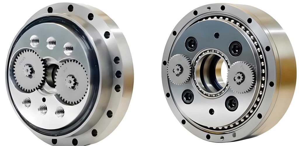
The pursuit of high precision, high rigidity, and high efficiency in precision transmission systems has positioned the RV reducer as a core component in advanced robotics and automation equipment. Its performance is paramount. Within the RV reducer, the meshing pair between the cycloid gear and the pin wheel is the final reduction stage and a primary source of power loss. Tooth profile modification of the cycloid gear is an essential design practice to compensate for manufacturing errors, facilitate assembly, and improve load distribution. While extensive research exists on the impact of profile modification on transmission accuracy, load capacity, and meshing characteristics, its direct influence on the critical lubrication performance between the teeth has often been overlooked. The quality of lubrication directly governs the transmission efficiency, operational temperature, wear rate, and ultimately the service life of the RV reducer. Since modification alters the meshing clearance and contact force distribution, it fundamentally affects the lubrication regime. Therefore, analyzing the effect of tooth profile modification schemes on lubrication performance is of significant theoretical and practical importance for the optimal design of RV reducers.
The lubrication between the cycloid gear and the pin teeth is a classic problem of elastohydrodynamic lubrication (EHL), typically involving grease as the lubricant. This study aims to establish a comprehensive thermal elastohydrodynamic (TEHL) numerical model for the line contact between these components. By obtaining full numerical solutions, we can analyze how different profile modification methods and amounts affect key lubrication parameters such as grease film pressure, thickness, temperature rise, and frictional power loss. This approach provides a novel methodology for designing cycloid gear profiles in RV reducers with explicit consideration of lubricity.
1. Establishment of the Numerical Lubrication Model
To analyze the limiting lubrication state, the TEHL model is established at the tooth pair experiencing the maximum contact force. This requires first developing a load distribution model for the RV transmission to identify the location and magnitude of the maximum load after profile modification.
1.1 Load Distribution Model for the Cycloid-Pin Meshing Pair
Profile modification creates initial clearance between the theoretical and manufactured tooth profiles. During operation, the cycloid gear teeth must overcome this clearance to engage, leading to a non-uniform load distribution. Assuming all teeth are in contact, the force on the i-th tooth can be expressed as:
$$F_i = \frac{\delta_i – \Delta(\varphi_i)}{\delta_{max}} F_{max}$$
where $\delta_i$ is the contact deformation at the i-th meshing point along the normal direction, $\Delta(\varphi_i)$ is the initial meshing clearance to be overcome, and $\delta_{max}$ and $F_{max}$ are the maximum contact deformation and maximum contact force, respectively. Their calculations involve several geometric and elastic parameters:
$$\delta_i = l_i \beta = \frac{\sin \varphi_i}{\sqrt{1+K_1^2-2K_1\cos\varphi_i}} \delta_{max}$$
$$\Delta(\varphi_i) = \Delta r_{rp} \left(1 – \frac{\sin \varphi_i}{\sqrt{1+K_1^2-2K_1\cos\varphi_i}}\right) – \frac{\Delta r_p \left(1 – K_1\cos\varphi_i – \sqrt{1-K_1^2}\sin\varphi_i\right)}{\sqrt{1+K_1^2-2K_1\cos\varphi_i}}$$
$$F_{max} = \frac{0.55 T_1}{\sum_{i=m}^{n} \left( \frac{l_i}{r_a^2} – \frac{\Delta(\varphi_i)}{\delta_{max}} \right) l_i}$$
$$\delta_{max} = w_{max} + f_{max}$$
Here, $l_i$ is the distance from the cycloid wheel center to the common normal line at the i-th contact point, $\beta$ is the rotation angle of the cycloid gear due to deformation under load, $K_1$ is the shortening coefficient, $\varphi_i$ is the angle of the i-th pin relative to the turning arm, $\Delta r_{rp}$ and $\Delta r_p$ are the equidistant and radial moving modification amounts, $T_1$ is the output torque, $r_a$ is the pitch radius of the cycloid gear, and $w_{max}$ and $f_{max}$ are the maximum contact deformation between the cycloid gear and pin and the maximum bending deformation of the pin, respectively.
Following this computational framework, the maximum contact force $F_{max}$ and its corresponding meshing position (characterized by angle $\psi$) can be determined iteratively. Subsequently, the entrainment velocity $u_r$ and equivalent radius of curvature $R$ at this critical contact point are calculated. The entrainment velocity is given by:
$$u_r = \frac{z_p \omega_H}{2z_c} \left\{ \frac{[r_p(1+K_1^2-2K_1\cos\psi)^{1/2} – r_{rp}]^2}{r_p(1+K_1^2-2K_1\cos\psi)^{1/2} – r_{rp}} + \frac{x^2+y^2 – r_a^2}{r_p(1+K_1^2-2K_1\cos\psi)^{1/2} – r_{rp}} \right\}$$
where $z_p$ and $z_c$ are the numbers of pin teeth and cycloid gear teeth, $\omega_H$ is the input angular velocity, $r_p$ is the pin center circle radius, and $r_{rp}$ is the pin radius. The equivalent radius of curvature $R$ for the meshing pair is:
$$R = \frac{\xi r_{rp}}{\xi \pm r_{rp}}$$
where the “+” sign is for convex-convex contact and the “-” for convex-concave contact. $\xi$ is the radius of curvature of the actual cycloid profile at the contact point:
$$\xi = \frac{(1+K_1^2-2K_1\cos\psi)^{3/2} r_p}{K_1(z_p+1)\cos\psi – (1+z_p K_1^2)} + r_{rp}$$
1.2 Thermal Elastohydrodynamic Grease Lubrication Model
Grease is typically modeled as a non-Newtonian fluid. The Ostwald-de Waele (power-law) model is often used to describe its rheological behavior:
$$\tau = \phi \left( \frac{du}{dz} \right)^n$$
where $\tau$ is the shear stress, $\phi$ is the consistency index (plastic viscosity function), $n$ is the flow behavior index, $u$ is the flow velocity, and $z$ is the coordinate across the film thickness. The viscosity-pressure-temperature relationship for the grease is incorporated as:
$$\phi = \phi_0 \exp\left\{ (\ln \eta_0 + 9.67) \left[ (1+1.98\times10^{-8}p)^{z_0} – 1 \right] \times \left( \frac{T-138}{T_0-138} \right)^{-s} \right\}$$
where $\phi_0$ and $\eta_0$ are the ambient-pressure consistency and viscosity, $T_0$ is the ambient temperature, $T$ is the local film temperature, $z_0 = \alpha / [5.1\times10^{-9} \ln(\eta_0+9.67)]$, $s = \beta (T_0-138)/\ln(\eta_0+9.67)$, $\alpha$ is the pressure-viscosity coefficient, and $\beta$ is the temperature-viscosity coefficient.
Considering line contact conditions, the steady-state one-dimensional Reynolds equation for the power-law fluid is:
$$\frac{n}{2n+1} \left( \frac{1}{2} \right)^{\frac{n+1}{n}} \frac{\partial}{\partial x} \left[ \rho h^{\frac{2n+1}{n}} \left( \frac{1}{\phi} \frac{\partial p}{\partial x} \right)^{\frac{1}{n}} \right] = u_r \frac{\partial (\rho h)}{\partial x}$$
with boundary conditions $p(x_{in}) = p(x_{out}) = 0$ and $p(x) > 0$ for $x_{in} < x < x_{out}$. Here, $\rho$ is the grease density and $h$ is the film thickness.
The film thickness equation accounting for geometry, elastic deformation, and rigid body displacement is:
$$h(x) = h_0 + \frac{x^2}{2R} + \upsilon_e(x)$$
where $h_0$ is the rigid body separation, and $\upsilon_e(x)$ is the elastic deformation of the surfaces, calculated using the Boussinesq integral:
$$\upsilon_e(x) = -\frac{4}{\pi E’} \int_{x_{in}}^{x_{out}} \ln |x-s|\, p(s)\, ds$$
The equivalent elastic modulus $E’$ is $E’ = \left[ (1-\nu_1^2)/E_1 + (1-\nu_2^2)/E_2 \right]^{-1}$, where $E$ and $\nu$ are the Young’s modulus and Poisson’s ratio of the two contacting materials (cycloid gear and pin).
The density of the grease varies with pressure and temperature according to:
$$\rho = \rho_0 \left[ \left( \frac{1 + 0.6 \times 10^{-9}p}{1 + 1.7 \times 10^{-9}p} \right) – 0.00065(T – T_0) \right]$$
The load balance equation must be satisfied over the contact domain:
$$\int_{x_{in}}^{x_{out}} p(x) \, dx = F_{max}$$
The friction power loss per unit width, resulting from shearing of the grease film, is calculated by integrating the product of shear stress and sliding velocity across the film:
$$Q = A \int_0^h \tau \frac{du}{dz} \, dz$$
where $A$ is the unit area in the direction of motion.
To account for thermal effects, the energy equation within the grease film is considered. Assuming heat conduction only in the z-direction and neglecting pressure variation across the film, the equation is:
$$c \left( \rho u \frac{\partial T}{\partial x} + q \frac{\partial T}{\partial z} \right) = k \frac{\partial^2 T}{\partial z^2} – \frac{T u}{\rho} \frac{\partial \rho}{\partial T} \frac{\partial p}{\partial x} + \phi \left( \frac{\partial u}{\partial z} \right)^2$$
where $c$ and $k$ are the specific heat and thermal conductivity of the grease, and $q = \frac{\partial}{\partial x} \int_0^z \rho u \, dz$. The velocity profile $u$ across the film is derived from the fluid mechanics equations for a power-law fluid.
The solids (cycloid gear and pin) are treated as semi-infinite bodies. Their energy equations, assuming heat is conducted mainly into the solids perpendicular to the surface, are:
$$c_a \rho_a u_1 \frac{\partial T}{\partial x} = k_a \frac{\partial^2 T}{\partial z_a^2}, \quad c_b \rho_b u_2 \frac{\partial T}{\partial x} = k_b \frac{\partial^2 T}{\partial z_b^2}$$
with boundary conditions $T(x_{in}, z_a) = T(x, -\infty) = T_0$ and $T(x_{in}, z_b) = T(x, \infty) = T_0$. The subscripts $a$ and $b$ denote the two contacting solids. At the fluid-solid interfaces, continuity of heat flux is enforced:
$$k_a \left. \frac{\partial T}{\partial z_a} \right|_{z_a=0} = k \left. \frac{\partial T}{\partial z} \right|_{z=0}, \quad k_b \left. \frac{\partial T}{\partial z_b} \right|_{z_b=0} = k \left. \frac{\partial T}{\partial z} \right|_{z=h}$$
2. Numerical Solution Method and Parameter Setup
The governing equations are normalized and discretized using the finite difference method. The pressure and temperature fields are solved iteratively. The elastic deformation is efficiently calculated using the Discrete Convolution and Fast Fourier Transform (DC-FFT) method. The solution process starts by obtaining the isothermal EHL solution. This solution is then used as an initial guess for the coupled thermal iteration, where the energy equations for the fluid and solids are solved until the pressure, film thickness, and temperature fields all converge to a steady state. This provides the complete TEHL solution for the RV reducer’s critical contact point.
The analysis is based on the parameters of a heavy-duty RV550-E type reducer. The basic parameters for the cycloid-pin pair and the grease are listed in the following tables.
| Parameter | Symbol | Value | Unit |
|---|---|---|---|
| Pin Center Circle Radius | $r_p$ | 165 | mm |
| Pin Radius | $r_{rp}$ | 5 | mm |
| Eccentricity | $e$ | 2.2 | mm |
| Number of Pin Teeth | $z_p$ | 60 | – |
| Number of Cycloid Gear Teeth | $z_c$ | 59 | – |
| Shortening Coefficient | $K_1$ | 0.8 | – |
| Tooth Width | $L$ | 25 | mm |
| Output Torque | $T_1$ | 9310 | N·m |
| Input Speed | $n$ | 300 | rpm |
| Slide-to-Roll Ratio | SRR | 0.1 | – |
| Parameter | Symbol | Value | Unit |
|---|---|---|---|
| Elastic Modulus (Gear & Pin) | $E$ | 2.06×10⁵ | MPa |
| Poisson’s Ratio | $\nu$ | 0.3 | – |
| Density (Solid) | $\rho_{a,b}$ | 7850 | kg/m³ |
| Specific Heat (Solid) | $c_{a,b}$ | 470 | J/(kg·K) |
| Thermal Conductivity (Solid) | $k_{a,b}$ | 46 | W/(m·K) |
| Grease Base Viscosity (Ambient) | $\eta_0$ | 0.08 | Pa·s |
| Flow Behavior Index | $n$ | 0.9 | – |
| Grease Density (Ambient) | $\rho_0$ | 870 | kg/m³ |
| Grease Specific Heat | $c$ | 2000 | J/(kg·K) |
| Grease Thermal Conductivity | $k$ | 0.14 | W/(m·K) |
| Pressure-Viscosity Coefficient | $\alpha$ | 2.91×10⁻⁸ | Pa⁻¹ |
| Temperature-Viscosity Coefficient | $\beta$ | 0.0476 | K⁻¹ |
| Ambient Temperature | $T_0$ | 313 | K |
3. Results and Discussion on RV Reducer Performance
3.1 Thermal vs. Isothermal Solution
Initial comparisons highlight the importance of the thermal model for the RV reducer. For a given modification ($\Delta r_{rp}=0.12$ mm, $\Delta r_p=0.07$ mm), the pressure distribution in both isothermal and thermal solutions exhibits the classic EHL shape: a Hertzian-like profile in the central contact region followed by a sharp pressure spike near the outlet. The film thickness shows a parallel central region with a constriction (necking) downstream of the pressure spike. Comparing the two solutions reveals that the central film thickness from the thermal analysis is slightly larger than that from the isothermal analysis, while the corresponding central pressure is also slightly higher. This seemingly counter-intuitive result—where heating (which reduces viscosity) leads to a thicker film—can be attributed to the density-temperature effect. The significant temperature rise within the film (especially in the middle layer) reduces the grease density. This variable-density effect enhances the load-carrying capacity in the parallel region. If this enhancement outweighs the load-capacity reduction from viscosity drop, a net increase in film thickness occurs. Isolating this effect by comparing isothermal solutions at different ambient temperatures confirms that pure viscosity reduction (without density change) leads to a thinner film, as expected.
3.2 Influence of Modification Amount
Analyzing the effect of increasing the equidistant modification amount ($\Delta r_{rp}$) reveals clear trends for the RV reducer’s lubrication state:
- Film Thickness & Shape: As modification increases, the film profile becomes steeper. The parallel region corresponding to the Hertzian contact zone widens. The minimum film thickness (located at the outlet constriction) generally decreases with increasing modification, and the severity of the necking correlates with the outlet pressure gradient.
- Pressure Distribution: Larger modification amounts shift the contact zone and outlet point. The contact area and the absolute pressure within it increase. The outlet pressure spike also generally increases in magnitude.
- Temperature Rise: The maximum and average film temperature rise increase significantly with modification amount. The region of substantial heating expands, and the peak temperature at the outlet rises, following the trend of the pressure gradient.
- Friction Power Loss: The distribution of friction loss power resembles the pressure distribution. Both the overall level and the peak value at the outlet increase substantially with larger modification amounts, directly impacting the efficiency of the RV reducer.
The underlying mechanism is that increased modification reduces the number of teeth sharing the load, leading to a higher maximum contact force $F_{max}$ at the critical tooth pair. The lubrication film responds to this increased load by experiencing higher pressure, greater shear, and consequently higher temperatures and friction losses. The film thickness initially may show a complex non-monotonic behavior due to competing effects of load and entrainment velocity changes but ultimately tends to decrease under severe loading.
3.3 Comparison of Different Profile Modification Schemes
The lubricating performance of different profile modification methods for the RV reducer is evaluated under the condition of the same maximum radial clearance between the modified and theoretical profiles. Four common schemes are compared: Equidistant modification, Radial moving modification, Positive Equidistant + Positive Radial Moving (combined), and Negative Equidistant + Negative Radial Moving (combined). The anti-bow modification is analyzed separately due to its different load distribution characteristics. Key results are summarized below.
| Modification Scheme | Modification Amount (mm) | $F_{max}$ (N) | $H_{min}$ (μm) | $Q$ (W) |
|---|---|---|---|---|
| Equidistant | $\Delta r_{rp}=0.001$ | 2689.8 | 1.8025 | 478.8 |
| $\Delta r_{rp}=0.01$ | 3171.3 | 1.8083 | 649.3 | |
| $\Delta r_{rp}=0.10$ | 5233.4 | 1.7831 | 1438.7 | |
| $\Delta r_{rp}=0.20$ | 6411.5 | 1.7541 | 1931.4 | |
| $\Delta r_{rp}=0.40$ | 7943.5 | 1.7141 | 2606.7 | |
| Radial Moving | $\Delta r_p=0.001$ | 2707.2 | 1.8030 | 484.9 |
| $\Delta r_p=0.01$ | 3326.5 | 1.8097 | 703.2 | |
| $\Delta r_p=0.10$ | 5943.7 | 1.7676 | 1730.1 | |
| $\Delta r_p=0.20$ | 7424.8 | 1.7286 | 2373.9 | |
| $\Delta r_p=0.40$ | 9234.7 | 1.6787 | 3202.8 | |
| Positive Combined | $\Delta r_{rp}=0.002, \Delta r_p=0.001$ | 2672.4 | 1.8021 | 473.0 |
| $\Delta r_{rp}=0.020, \Delta r_p=0.010$ | 2997.9 | 1.8078 | 586.9 | |
| $\Delta r_{rp}=0.200, \Delta r_p=0.100$ | 4394.3 | 1.7993 | 1107.7 | |
| $\Delta r_{rp}=0.400, \Delta r_p=0.200$ | 5118.3 | 1.7855 | 1392.9 | |
| $\Delta r_{rp}=0.800, \Delta r_p=0.400$ | 6127.1 | 1.7623 | 1811.7 | |
| Negative Combined | $\Delta r_{rp}=-0.001, \Delta r_p=-0.002$ | 2724.6 | 1.8033 | 491.5 |
| $\Delta r_{rp}=-0.010, \Delta r_p=-0.020$ | 3476.6 | 1.8085 | 761.0 | |
| $\Delta r_{rp}=-0.100, \Delta r_p=-0.200$ | 6554.2 | 1.7513 | 1991.5 | |
| $\Delta r_{rp}=-0.200, \Delta r_p=-0.400$ | 8183.1 | 1.7075 | 2716.2 |
The table demonstrates two overarching trends for the RV reducer: 1) As the radial clearance (modification amount) increases, the maximum contact force $F_{max}$ and the total frictional power loss $Q$ increase monotonically for all schemes. 2) The minimum film thickness $H_{min}$ exhibits a non-monotonic behavior: it initially increases slightly with very small clearance due to strong entrainment effects in a growing contact area, but then decreases as the load becomes the dominant factor.
More importantly, comparing schemes at similar levels of radial clearance reveals significant differences in lubrication performance. The Positive Combined modification (positive equidistant + positive radial moving) consistently results in the lowest $F_{max}$ and $Q$ among the standard schemes, followed by the equidistant modification. The Negative Combined modification yields the worst performance, with the highest contact force and friction loss. This is because the negative combined modification effectively reduces the overall curvature of the engaging tooth profile, leading to poorer load-sharing and higher stress concentration.
The analysis of the anti-bow modification requires a full meshing cycle comparison because its point of maximum load differs. When comparing the minimum film thickness and friction power loss at all meshing positions for the same maximum radial clearance, the anti-bow profile demonstrates superior performance. It maintains a higher minimum film thickness and lower friction loss across the majority of the load-bearing arc compared to the other modification methods. Although its friction loss may be higher at the very ends of the contact arc, these positions carry minimal load and contribute little to the total energy loss. Therefore, from an overall lubrication performance perspective for the RV reducer, the anti-bow modification appears to be the most favorable among the methods considered.
4. Conclusion
This study establishes a thermal elastohydrodynamic lubrication model for the critical line contact within an RV reducer, specifically between the cycloid gear and pin teeth. The model incorporates the non-Newtonian behavior of grease and thermal effects, providing a realistic analysis of the lubrication state under different tooth profile modification strategies. The key findings for RV reducer design are:
- The thermal model is essential for accurate prediction. The variable-density effect of grease with temperature can influence film thickness predictions, underscoring the need for a coupled thermal-mechanical analysis in high-precision RV reducers.
- The amount of profile modification has a profound impact. Increasing the radial clearance generally leads to higher maximum contact stress, higher film temperature, and significantly increased frictional power loss, which reduces the efficiency of the RV reducer. The minimum film thickness shows a complex, non-monotonic relationship with modification amount.
- The choice of modification scheme is critical. For the same maximum radial clearance, the anti-bow profile modification offers the best overall lubrication performance, characterized by a thicker minimum film and lower friction loss. Among more traditional schemes, the positive equidistant combined with positive radial moving modification provides better lubricity (lower friction and load) compared to equidistant alone or radial moving alone. Negative combined modifications should be avoided as they result in the poorest lubrication performance for the RV reducer.
This work presents a new methodology that integrates lubrication performance directly into the tooth profile modification design process for RV reducers. By simulating the TEHL conditions resulting from different modifications, designers can make informed choices that balance transmission accuracy, load capacity, and energy efficiency—ultimately leading to more reliable and high-performing RV reducers for robotic and precision drive applications.