
In the field of precision machinery and industrial robotics, the RV reducer plays a critical role due to its compact design, high transmission ratio, and excellent torsional stiffness. As an essential component of the RV reducer, the cycloid drive system, which includes cycloid wheels and pin gears, is subjected to complex dynamic loads during operation. Over time, localized faults such as spalling can occur on the cycloid wheel teeth, leading to increased vibration, noise, and potential system failure. In this study, I focus on investigating the vibration characteristics of the RV reducer when a spalling fault is present on the cycloid wheel. By employing finite element analysis and experimental validation, I aim to provide insights into fault detection and prognosis for RV reducers, thereby enhancing their reliability and safety in industrial applications.
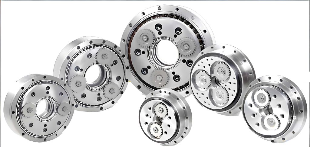
The RV reducer, short for Rotary Vector reducer, is a type of precision gearbox commonly used in robots and automated systems. It consists of a two-stage transmission system: the first stage is a planetary gear train with spur gears, and the second stage is a cycloid drive mechanism. The cycloid drive involves cycloid wheels that mesh with a pin gear housing, generating motion through eccentric rotation. This design allows for high reduction ratios and minimal backlash, but it also introduces dynamic excitations that can lead to vibration issues. Understanding the vibration response under fault conditions is crucial for predictive maintenance. In this context, I develop a detailed finite element model of the RV reducer with a spalling fault on the cycloid wheel, simulate its dynamic behavior, and analyze the resulting vibration signals to identify characteristic patterns associated with the fault.
To begin, I establish the parametric equations for the cycloid wheel profile, which is fundamental for accurate modeling. The cycloid curve is generated by a rolling circle on a base circle, and its mathematical representation in Cartesian coordinates is derived from pure rolling conditions. Let \( R \) be the radius of the base circle, \( r \) the radius of the rolling circle, \( \theta \) the rotation angle of the base circle, and \( \beta \) the rotation angle of the rolling circle. From the arc length equality, we have:
$$ \beta = \frac{R}{r} \theta $$
The coordinates of a point on the cycloid can be expressed as:
$$ x = (R + r) \cos \theta – \cos \alpha $$
$$ y = (R + r) \sin \theta + \sin \alpha $$
where \( \alpha = 2\pi – \theta – \beta \). Substituting \( \beta \), the parametric equations become:
$$ x = (R + r) \cos \theta – \cos\left(1 + \frac{R}{r}\right) \theta $$
$$ y = (R + r) \sin \theta – \sin\left(1 + \frac{R}{r}\right) \theta $$
These equations are used to define the tooth profile of the cycloid wheel in the 3D model. For the RV reducer under study, the key parameters are listed in Table 1, which are essential for constructing the geometry and ensuring simulation accuracy.
| Parameter | Value |
|---|---|
| Number of sun gear teeth | 12 |
| Number of planetary gear teeth | 44 |
| Number of cycloid wheel teeth | 59 |
| Number of pin gear teeth | 60 |
| Pressure angle (°) | 20 |
| Eccentricity (mm) | 2.4 |
| Planetary gear width (mm) | 16 |
| Pin gear diameter (mm) | 10 |
| Pin gear center circle diameter (mm) | 165 |
Using these parameters, I create a 3D model of the RV reducer assembly in ABAQUS software. The model includes the sun gear, planetary gears, cycloid wheels, pin gear housing, and crankshafts. To simulate a spalling fault, I introduce a localized defect on one tooth of the cycloid wheel by removing material to a depth of 0.5 mm at the tooth edge, mimicking typical spalling damage observed in practice. The fault is modeled as a small cavity, which affects the meshing behavior and induces vibration changes. The assembly is simplified by removing non-essential features like chamfers and holes to reduce computational complexity, while maintaining the structural integrity of the RV reducer for dynamic analysis.
Next, I proceed to build the finite element model for the RV reducer. This involves several steps: defining material properties, meshing, setting up contact interactions, applying boundary conditions, and configuring the solver. The material used for all components is structural steel, with properties as shown in Table 2. These properties are critical for accurate stress and vibration predictions in the RV reducer.
| Property | Value |
|---|---|
| Material | Steel (Structural) |
| Density, \( \rho \) (t/mm³) | 7.85 × 10⁻⁹ |
| Elastic modulus, \( E_1 \) (MPa) | 2.1 × 10⁵ |
| Poisson’s ratio, \( \mu \) | 0.3 |
For meshing, I use tetrahedral elements with linear geometry order to ensure consistent mesh quality across the RV reducer assembly. The total number of elements is 231,142 with 53,332 nodes for the entire system, and for the cycloid wheel with spalling fault, there are 55,965 elements and 12,374 nodes, accounting for mesh distortion near the fault area. The contact pairs are defined between mating components: sun gear-planetary gear and cycloid wheel-pin gear housing. The contact parameters include a friction coefficient of 0.15 for tangential behavior and hard contact for normal behavior in gear pairs, while for the cycloid-pin contact, a linear soft contact with a stiffness of 500 MPa is used to capture realistic interaction in the RV reducer. Boundary conditions are applied to simulate operational conditions: the pin gear housing is fixed, the planetary carrier is allowed displacement in the x-direction, and the sun gear is rotated by 1 radian in the x-direction to drive the system. The analysis is performed using explicit dynamics with a time period of 0.5 seconds and a mass scaling factor to improve computational efficiency.
With the finite element model set up, I conduct simulations for two cases: the RV reducer with a healthy cycloid wheel and the RV reducer with a spalling fault on the cycloid wheel. The primary outputs are Mises stress distributions and acceleration responses, which are analyzed to understand the vibration characteristics. For stress analysis, I extract Mises stress contours from the cycloid wheel and pin gear housing. Under spalling fault conditions, the cycloid wheel shows higher Mises stress compared to the healthy case, as the fault reduces the effective load-bearing area, leading to stress concentration. However, for the pin gear housing, the stress values remain relatively unchanged due to the small size of the fault and the housing’s thickness, indicating that stress alone may not be a reliable indicator for fault prognosis in the RV reducer.
In contrast, acceleration responses provide more distinct insights. The acceleration clouds for both the cycloid wheel and pin gear housing reveal significant increases under spalling fault conditions. Specifically, the acceleration magnitude on the cycloid wheel with fault is substantially higher than that on the healthy wheel, and similarly, the pin gear housing experiences greater vibration impacts when meshing with the faulty cycloid wheel. To quantify this, I select a point A on the pin gear housing and plot the time-domain acceleration signals along the x-direction for both cases, as shown in Figure 1. After an initial transient period (0.05 seconds), the signal stabilizes, and in the faulty case, a sharp impact peak is observed around 0.28 seconds, with an amplitude about 10 times larger than that in the healthy case. This impact corresponds to the moment when the faulty tooth engages with the pin gear, generating a distinct vibration signature that can be used for fault detection in the RV reducer.
To further analyze the vibration characteristics, I perform frequency-domain analysis using short-time Fourier transform on the acceleration signals. The frequency spectra for the faulty and healthy RV reducer cases are compared. In the faulty case, the meshing frequency exhibits sidebands due to modulation effects caused by the periodic impact of the spalling fault. The sidebands are spaced at approximately 1,454 Hz, which corresponds to the fault passage frequency. Additionally, the meshing frequency in the faulty case has a longer period and higher amplitude compared to the healthy case. These features—sidebands, increased amplitude, and altered frequency structure—serve as robust indicators for spalling fault prognosis in the RV reducer. The mathematical representation of modulation can be expressed as:
$$ s(t) = A(t) \cos(2\pi f_m t + \phi(t)) $$
where \( s(t) \) is the vibration signal, \( A(t) \) is the amplitude modulated by the fault impact, \( f_m \) is the meshing frequency, and \( \phi(t) \) is the phase modulation. For a spalling fault with passage frequency \( f_p \), the spectrum shows sidebands at \( f_m \pm k f_p \) for integer \( k \), confirming the observed patterns in the RV reducer simulation.
To validate the simulation results, I conduct an experimental study using an RV reducer performance test bench. The setup includes a drive motor, load motor, torque-speed sensors, encoders, and a data acquisition system. An IEPE triaxial accelerometer is mounted on the pin gear housing to measure vibration signals, mimicking the simulation setup. Two RV reducers are tested: one with a healthy cycloid wheel and one with a manufactured spalling fault on the cycloid wheel. The input speed is set to 500 rpm, load torque to 60 Nm, sampling frequency to 15 kHz, and data points to 32,768. The experimental frequency spectra, as shown in Figure 2, reveal similar characteristics to the simulation: in the faulty RV reducer, distinct peaks appear with sidebands around the meshing frequency, while the healthy case shows lower amplitudes and less modulation. The experimental fault passage frequency aligns closely with the simulated value, confirming the accuracy of the finite element model for the RV reducer.
The consistency between simulation and experiment underscores the reliability of using vibration analysis for fault diagnosis in RV reducers. The key findings from this study are summarized in Table 3, which highlights the vibration characteristics under spalling fault conditions. These insights can be integrated into condition monitoring systems for RV reducers in industrial applications, enabling early fault detection and reducing downtime.
| Aspect | Healthy RV Reducer | RV Reducer with Spalling Fault |
|---|---|---|
| Mises Stress on Cycloid Wheel | Lower, uniform distribution | Higher, concentrated near fault |
| Acceleration Magnitude | Lower peaks in time domain | Higher peaks (up to 10× increase) |
| Frequency Spectrum | Clear meshing frequency, minimal sidebands | Meshing frequency with sidebands at \( f_m \pm k f_p \) |
| Fault Passage Frequency | Not applicable | Approximately 1,454 Hz |
| Impact on Pin Gear Housing | Moderate vibration | Significant vibration shocks |
In conclusion, this study demonstrates the effectiveness of finite element modeling and vibration analysis for studying spalling faults in RV reducers. By comparing healthy and faulty states, I identify key vibration signatures—such as time-domain impact peaks and frequency-domain sidebands—that can be used for fault prognosis. The RV reducer’s dynamic response is sensitive to localized defects, making vibration monitoring a viable tool for predictive maintenance. Future work could explore other fault types, such as cracks or wear, and integrate machine learning algorithms for automated fault diagnosis in RV reducers. Overall, this research contributes to enhancing the reliability and safety of RV reducers in precision-driven industries.
From a theoretical perspective, the vibration dynamics of the RV reducer can be modeled using equations of motion that account for time-varying mesh stiffness and damping. For a cycloid drive system, the equation for forced vibration can be written as:
$$ M \ddot{x} + C \dot{x} + K(t) x = F(t) $$
where \( M \) is the mass matrix, \( C \) is the damping matrix, \( K(t) \) is the time-varying stiffness matrix due to meshing cycles in the RV reducer, and \( F(t) \) is the external force vector. Under a spalling fault, \( K(t) \) and \( F(t) \) exhibit periodic disturbances, leading to the modulated vibration responses observed. This theoretical framework supports the simulation and experimental findings, providing a foundation for advanced fault analysis in RV reducers.
Moreover, the use of advanced signal processing techniques, such as envelope analysis and wavelet transform, could further enhance fault detection in RV reducers. For instance, the envelope of the vibration signal can highlight impact events, while wavelet analysis can localize fault features in time-frequency domains. Integrating these methods with the finite element approach offers a comprehensive strategy for monitoring the health of RV reducers in real-time applications.
In summary, the RV reducer is a critical component in modern machinery, and its failure due to spalling faults can have severe consequences. Through detailed modeling and analysis, this study provides valuable insights into the vibration characteristics associated with such faults, paving the way for improved maintenance practices and extended service life of RV reducers. The methodologies developed here can be adapted to other gear systems, contributing broadly to the field of mechanical fault diagnosis and prognosis.