
In the realm of precision robotics and high-performance automation, the Rotary Vector (RV) reducer stands as a critical component. Its compact design, high torque capacity, large reduction ratio, and exceptional torsional rigidity make it the drive element of choice for robotic joints. However, one of the primary sources of vibration and noise in these systems is transmission error. This error, defined as the deviation between the actual and theoretical angular position at the output shaft, arises from a combination of manufacturing inaccuracies, assembly misalignments, and elastic deformations under load. Understanding, measuring, and minimizing this error is paramount for enhancing the precision, smoothness, and longevity of robotic systems. This article presents a detailed experimental investigation into the transmission error of an RV reducer, specifically the RV-40E model. The study explores the influences of input rotational speed and operational load on transmission error and extends the analysis to a comparative performance evaluation against both domestic and leading international products.
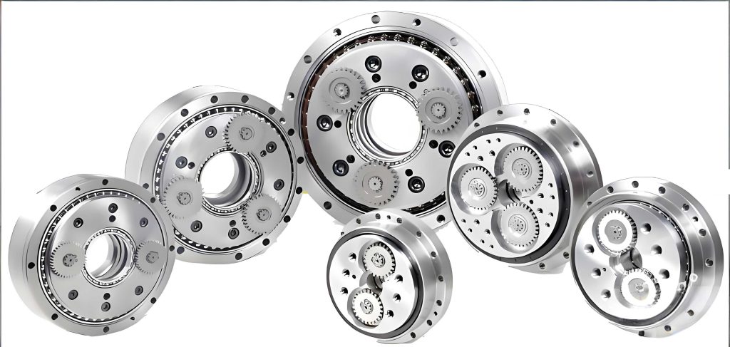
The core operational principle of the RV reducer involves a two-stage reduction mechanism. The first stage is a standard planetary gear train, which provides an initial speed reduction. The second, and defining, stage is a cycloidal drive consisting of a crankshaft, cycloidal discs, and a ring of pin gears housed in a pin gear housing. This unique configuration is responsible for the RV reducer’s high reduction ratio and compact size. The transmission error ($E$) is quantitatively defined by the following relationship between the input and output shafts:
$$E = \frac{\theta_{in}}{R} – \theta_{out}$$
where $\theta_{in}$ is the measured rotation angle at the input shaft, $\theta_{out}$ is the measured rotation angle at the output shaft, and $R$ is the nominal reduction ratio of the RV reducer. For the RV-40E model under test, $R = 121$. A positive value of $E$ indicates that the output lags behind its theoretical position, while a negative value suggests it is ahead.
The experimental setup for this investigation was a dedicated RV reducer test platform. The core of the system was a precisely aligned test bench where the RV reducer was mounted. The input side was connected to a servo drive motor coupled with a high-resolution torque and angle sensor. The output side was connected to a programmable magnetic powder brake for applying controlled load torques, also instrumented with its own torque and angle sensor. This configuration allowed for closed-loop control of both input speed and output load, enabling the collection of synchronized, high-fidelity data on input angle, output angle, and torque under various operational conditions. The test platform was capable of handling input power up to 1.8 kW, output torque up to 1000 N·m, and input speeds up to 3000 rpm, well exceeding the requirements for testing the RV-40E.
The first phase of testing focused on characterizing the transmission error of the RV reducer under no-load conditions. The reducer was operated at four distinct constant input speeds: 10 rpm, 20 rpm, 30 rpm, and 40 rpm, with zero torque applied at the output. For each speed, the input and output angular positions were recorded over several complete revolutions. The transmission error was calculated in real-time using the formula above and plotted as a function of the output shaft angle. The key metrics extracted from these plots were the peak-to-peak transmission error (the difference between the maximum and minimum error values over one cycle) and the mean error. The results are summarized comprehensively in the table below.
| Input Speed (rpm) | Minimum Error (arcseconds) | Maximum Error (arcseconds) | Peak-to-Peak Error (arcseconds) |
|---|---|---|---|
| 10 | -25 | 14 | 39 |
| 20 | -13 | 27 | 40 |
| 30 | -10 | 29 | 39 |
| 40 | -13 | 28 | 41 |
Analysis of the no-load data reveals a consistent pattern. The peak-to-peak transmission error for this particular RV reducer remained remarkably stable, hovering around 40 arcseconds, regardless of the input speed increase from 10 to 40 rpm. This suggests that the fundamental geometric imperfections and clearances within the gear meshes—such as cycloid disc profile errors, pin gear position errors, and bearing clearances—are the dominant factors under unloaded conditions. The slight fluctuations in the maximum and minimum values are likely due to measurement noise and minor variations in the engagement conditions as speed changes. The near-constant error range implies that, in a no-load state, the dynamic effects of increasing rotational inertia or minor lubrication variations have a negligible impact on the overall error magnitude for this RV reducer.
The second and more revealing phase of the experiment involved testing under loaded conditions. A constant load torque, corresponding to the rated operational load for the RV-40E, was applied at the output shaft. The same sequence of input speeds (10, 20, 30, and 40 rpm) was tested again. Applying a load fundamentally changes the internal state of the RV reducer; gear teeth and components experience elastic deformation, and the meshing forces between the cycloidal discs and pin gears increase significantly, potentially altering the engagement characteristics and error profile.
| Input Speed (rpm) | Minimum Error (arcseconds) | Maximum Error (arcseconds) | Peak-to-Peak Error (arcseconds) |
|---|---|---|---|
| 10 | -23 | 13 | 36 |
| 20 | -13 | 26 | 39 |
| 30 | -8 | 28 | 36 |
| 40 | -12 | 27 | 39 |
A direct comparison between the loaded and unloaded data yields critical insights. Contrary to what might be intuitively expected, the application of a rated load did not drastically increase the transmission error. In fact, at the lower speeds (10 and 30 rpm), the peak-to-peak error was slightly smaller under load. This can be explained by the damping effect of the load. Under no-load conditions, the system is more susceptible to minor vibrations and oscillations within the gear train and linkages. The applied load increases the normal forces at all contact interfaces, which can suppress these free vibrations and lead to a more stable, consistent meshing action, thereby slightly reducing the observed error range. This highlights a key performance aspect: a well-designed and manufactured RV reducer maintains or even improves its kinematic precision under its designed operational load.
However, a trend becomes apparent when observing the effect of increasing input speed under load. While the error range remains similar to the no-load case, the data suggests a slight upward trend in the maximum recorded error values as speed increases from 10 to 30 rpm. This can be attributed to dynamic effects. At higher input speeds, the rate of change of forces and accelerations within the RV reducer increases. While the load provides damping, the inertial forces and the transient response of the components to the rapidly changing meshing conditions can induce minor torsional wind-up and dynamic deflection. These effects are often modeled as a function of speed and acceleration. The relationship between dynamic torque ($T_d$), moment of inertia ($J$), and angular acceleration ($\alpha$) is given by $T_d = J \alpha$. Although the test was at constant speed, the engagement of each tooth is a small acceleration/deceleration event. The increased frequency of these events at higher speed can lead to a higher probability of capturing these dynamic deflections in the error measurement, slightly elevating the peak error values.
To place the performance of the test unit (a domestically produced RV-40E) into a broader industrial context, a comparative analysis was conducted. Transmission error measurements were taken from several other RV reducers available on the market, including units from other domestic manufacturers and a unit from Nabtesco, a world-leading Japanese manufacturer of precision RV reducers often considered the industry benchmark. The key comparative metric was the peak-to-peak transmission error measured under similar test conditions.
| Manufacturer / Product Origin | Measured Peak-to-Peak Transmission Error (arcseconds) |
|---|---|
| Domestic Manufacturer A | 47 |
| Domestic Manufacturer B | 70 |
| Domestic Manufacturer C | 59 |
| Nabtesco (Japan) | 42 |
| Test Unit (RV-40E, this study) | 36 – 41 |
The comparative data reveals a significant spread in the performance of RV reducers. The national standard for high-precision RV reducers often specifies a maximum allowable transmission error, commonly in the range of 60 arcseconds. While some domestic products (like Manufacturer B’s unit at 70 arcseconds) exceed this limit, indicating potential issues in manufacturing consistency or design, others are well within it. The test unit from this study, with an error range of 36-41 arcseconds, not only complies comfortably with the standard but also shows a performance level that is competitive with, and in this specific instance slightly superior to, the benchmark Nabtesco unit (42 arcseconds). This demonstrates that advanced domestic manufacturing capabilities for critical components like the RV reducer have reached a stage where they can achieve world-class precision levels. The variation among domestic brands underscores the importance of rigorous quality control and advanced manufacturing techniques in the production of high-performance RV reducers.
In conclusion, this experimental investigation provides a clear, data-driven perspective on the transmission error behavior of an RV reducer. The study demonstrates that for a high-quality unit, the fundamental transmission error, dictated by geometric precision, is the primary contributor and remains relatively stable across a range of input speeds. The application of a rated operational load can have a slight stabilizing effect, reducing error oscillation compared to the no-load state. Furthermore, the performance of the tested RV-40E reducer validates that contemporary domestic manufacturing can produce RV reducers whose core kinematic accuracy meets or exceeds that of established international leaders. Continuous research and development focusing on ultra-precision machining of cycloid profiles, optimization of bearing preload and gear clearances, and advanced assembly techniques are essential to further push the boundaries of RV reducer performance, enabling the next generation of even more precise and reliable robotic systems.