
In the field of precision robotics and industrial automation, the RV reducer plays a pivotal role due to its compact design, high torque capacity, and exceptional positioning accuracy. As a key component of the RV reducer, the cycloidal pin wheel transmission is subjected to complex contact stresses during operation, which directly influences the reducer’s lifespan, efficiency, and vibrational characteristics. Therefore, a detailed investigation into the transient contact behavior of the cycloidal pin wheel pair under load is essential for optimizing design and ensuring reliability. This article presents a comprehensive finite element analysis (FEA) focusing on the initial meshing moment of the cycloidal pin wheel, considering factors such as tooth profile modification and realistic boundary conditions. The goal is to elucidate the contact state, stress distribution, and deformation patterns, providing insights for engineering applications.
The RV reducer, an abbreviation for Rotate Vector reducer, is a two-stage precision gearbox commonly used in robotic joints, machine tools, and aerospace systems. Its structure integrates a first-stage planetary gear train with involute gears and a second-stage cycloidal pin wheel mechanism. The cycloidal stage is responsible for the high reduction ratio and smooth torque transmission. The core of this stage consists of a cycloidal disk (or wheel) meshing with a set of pins housed in a pin wheel. Under operational loads, the contact between the cycloidal teeth and the pins is not uniform, leading to localized stresses that can affect performance. Hence, analyzing this contact using advanced numerical methods like FEA is crucial.
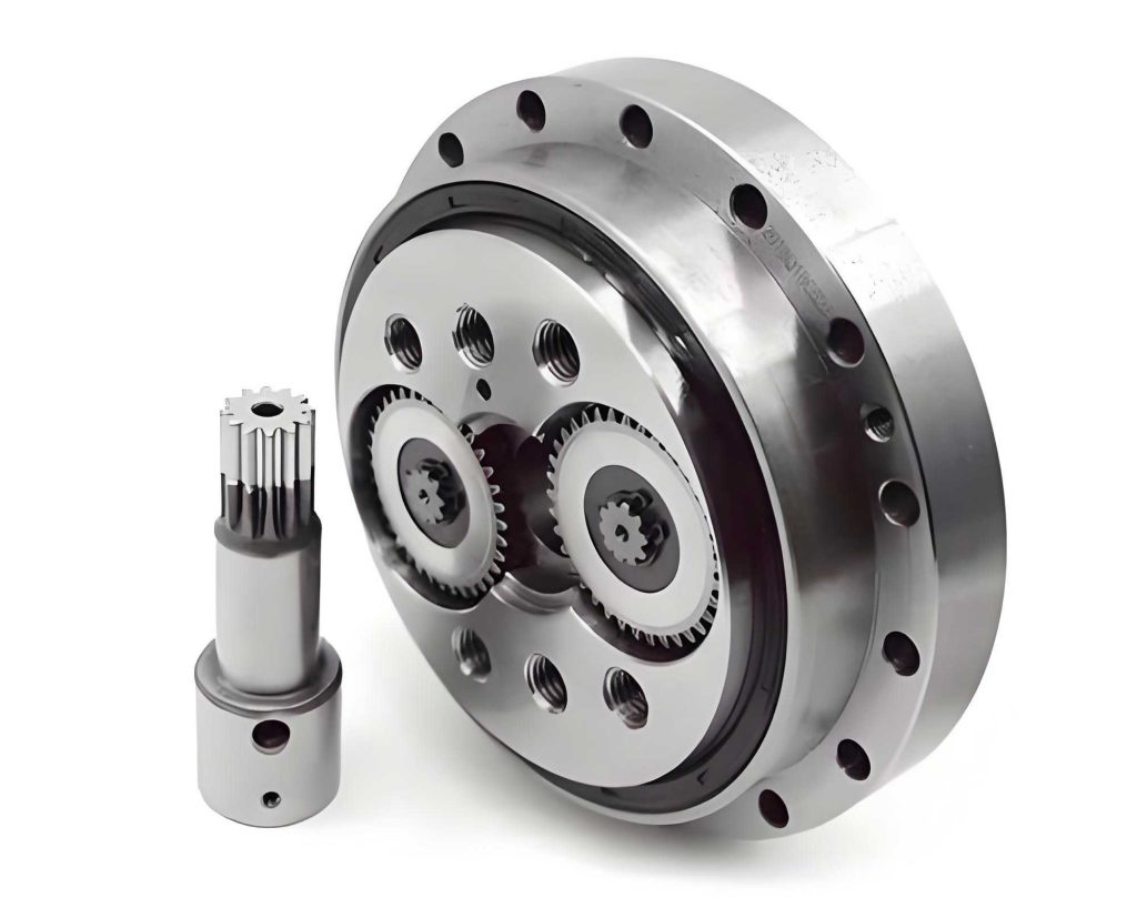
The fundamental working principle of the RV reducer involves input rotation from a servo motor driving the central sun gear, which then engages with planetary gears mounted on crankshafts. This constitutes the first reduction stage. The crankshafts, through eccentric motion, drive the cycloidal disks. As the cycloidal disks rotate eccentrically relative to the fixed pin wheel, their teeth engage with the pins, causing the cycloidal disks to rotate relative to the pins. This motion is then transferred to the output via a planet carrier, achieving the second-stage reduction. The overall reduction ratio is high, often exceeding 100:1, making the RV reducer ideal for applications requiring precise, high-torque output. Understanding the mechanics of the cycloidal pin wheel pair is foundational to any contact analysis.
To accurately model the cycloidal pin wheel pair, it is imperative to derive the mathematical representation of the cycloidal tooth profile. The standard cycloidal profile is generated based on the epitrochoidal principle. For a cycloidal disk with tooth number \(Z_c\) and a pin wheel with pin number \(Z_p\), the parametric equations for the tooth profile without modification are given by:
$$
x(\theta) = (R_p – r_p) \cos \theta – e \cos\left(\frac{Z_p}{Z_c} \theta\right) – r_p \cos\left(\theta – \phi(\theta)\right)
$$
$$
y(\theta) = (R_p – r_p) \sin \theta + e \sin\left(\frac{Z_p}{Z_c} \theta\right) – r_p \sin\left(\theta – \phi(\theta)\right)
$$
where:
- \(R_p\) is the radius of the pin wheel pitch circle,
- \(r_p\) is the radius of the pins,
- \(e\) is the eccentricity of the crankshaft,
- \(\theta\) is the parameter angle, and
- \(\phi(\theta) = \arctan\left(\frac{e \sin\left(\frac{Z_p}{Z_c} \theta\right)}{R_p – r_p – e \cos\left(\frac{Z_p}{Z_c} \theta\right)}\right)\).
In practice, to ensure proper meshing and reduce stress concentrations, the cycloidal tooth profile is often modified. Common modifications include equidistant modification (changing \(r_p\)) and moving distance modification (changing \(R_p\)). The modified profile equations incorporate these adjustments, leading to a slight deviation from the standard profile to optimize contact. For instance, if \(\Delta r_p\) is the equidistant modification and \(\Delta R_p\) is the moving distance modification, the modified equations become:
$$
x_m(\theta) = (R_p + \Delta R_p – (r_p + \Delta r_p)) \cos \theta – e \cos\left(\frac{Z_p}{Z_c} \theta\right) – (r_p + \Delta r_p) \cos\left(\theta – \phi_m(\theta)\right)
$$
$$
y_m(\theta) = (R_p + \Delta R_p – (r_p + \Delta r_p)) \sin \theta + e \sin\left(\frac{Z_p}{Z_c} \theta\right) – (r_p + \Delta r_p) \sin\left(\theta – \phi_m(\theta)\right)
$$
with \(\phi_m(\theta) = \arctan\left(\frac{e \sin\left(\frac{Z_p}{Z_c} \theta\right)}{R_p + \Delta R_p – (r_p + \Delta r_p) – e \cos\left(\frac{Z_p}{Z_c} \theta\right)}\right)\).
These equations are crucial for generating an accurate geometric model of the cycloidal disk. In this analysis, the ANSYS Parametric Design Language (APDL) was employed to create a parameterized three-dimensional model of the cycloidal pin wheel pair. This approach avoids geometric inaccuracies that may arise from importing CAD models and allows for easy variation of design parameters. The model simplification involved considering a single cycloidal disk and a set of pins, with pin length equal to the disk width, to enhance computational efficiency while preserving the essential contact physics.
The finite element model construction requires careful selection of element types and mesh strategies. For this contact analysis, SOLID185 elements were chosen due to their suitability for three-dimensional structural simulations. SOLID185 is an 8-node hexahedral element with three degrees of freedom per node (translations in X, Y, Z directions), capable of modeling complex stress states and large deformations. Hexahedral elements generally offer better accuracy and lower sensitivity to distortion compared to tetrahedral elements, making them ideal for contact problems in RV reducers. The mesh was generated using the VSWEEP command in ANSYS, with local refinement near the contact surfaces to capture high stress gradients. The contact regions on the cycloidal teeth were meshed with an element size of 0.25 mm, while the rest of the model used a coarser size of 1 mm to balance accuracy and computational cost.
Contact pair definition is critical for simulating the interaction between the cycloidal disk and pins. Given that both components are made of steel, a flexible surface-to-surface contact formulation was adopted. The cycloidal tooth surfaces were defined as target surfaces (using TARGE170 elements), and the pin surfaces as contact surfaces (using CONTA174 elements). The contact properties included a friction coefficient of 0.3 to account for sliding effects. Since the modified profile initially results in single-tooth contact, the contact settings were adjusted to eliminate initial penetration and maintain gaps (KEYOPT settings: K5=0, K9=1, K12=0). The augmented Lagrange algorithm was selected for its robustness in solving contact problems. For the initial meshing moment, contact pairs were established for the first 13 teeth, as these were deemed potentially engaged under load.
The boundary conditions and loading must replicate the actual operating scenario of the RV reducer. In this case, the pin wheel is fixed, and the output is through the planet carrier. To simulate this, the pins were constrained in all translational degrees of freedom and rotations about X and Y axes. The cycloidal disk’s motion involves both rotation about its own axis and revolution around the pin wheel center. This was modeled using multipoint constraint (MPC) elements. Specifically, MPC184 elements were created at the centers of the two crankshaft holes on the cycloidal disk and at the pin wheel center. A MASS21 element was placed at the cycloidal disk center hole. Constraints and coupling equations were applied to link these MPCs to the corresponding nodes, simulating the connection to the crankshafts and output carrier. The eccentric motion was enforced by constraining the cycloidal disk center element’s translations and rotations appropriately, allowing only the necessary degrees of freedom for revolution.
The load applied corresponds to the rated output torque of the RV reducer. For this analysis, a torque of 167 N·m was considered, which is typical for such reducers in robotic applications. The torque was applied indirectly through the boundary conditions that induce the eccentric motion, resulting in contact forces between the cycloidal teeth and pins. The material properties for both the cycloidal disk and pins were assumed to be linear elastic, with Young’s modulus of 206 GPa and Poisson’s ratio of 0.3, representative of high-strength alloy steel.
The geometric and material parameters used in this finite element analysis are summarized in the following tables, which are essential for reproducibility and understanding the simulation setup. These parameters are typical for a medium-sized RV reducer used in industrial robots.
| Parameter | Symbol | Value | Unit |
|---|---|---|---|
| Number of cycloidal teeth | \(Z_c\) | 39 | – |
| Number of pins | \(Z_p\) | 40 | – |
| Pin wheel pitch radius | \(R_p\) | 52.5 | |
| Pin radius | \(r_p\) | 2.35 | |
| Eccentricity | \(e\) | 0.9 | |
| Cycloidal disk pitch radius | \(r_c\) | 35.1 | |
| Reference radius for bearing holes | \(l\) | 24 | |
| Width of cycloidal disk | \(b\) | 8.9 | |
| Output speed | \(n\) | 15 |
| Component | Young’s Modulus (GPa) | Poisson’s Ratio |
|---|---|---|
| Cycloidal disk | 206 | 0.3 |
| Pins | 206 | 0.3 |
| Modification Type | Symbol | Value (μm) |
|---|---|---|
| Equidistant modification | \(\Delta r_p\) | 5.69 |
| Moving distance modification | \(\Delta R_p\) | -3.68 |
With the model established, the finite element analysis was performed to evaluate the contact state at the initial meshing instant under load. The results reveal several key insights into the behavior of the RV reducer’s cycloidal stage. The von Mises stress distribution on the cycloidal disk indicates that, contrary to the unloaded condition where only one tooth might be in contact, the application of torque leads to multiple teeth sharing the load. Specifically, at the initial moment, six teeth were found to be actively engaged in force transmission. This multi-tooth contact is attributed to elastic deformation of the cycloidal disk under load, which compensates for the clearances introduced by profile modification, thereby distributing the stress more evenly.
The contact stress on the meshing tooth pairs was extracted, and the maximum contact stress for each engaged tooth is plotted in a curve. The analysis shows that the highest contact stress occurs at the sixth tooth from the reference position, indicating that this tooth is the first to come into contact and bears the brunt of the load initially. The contact stress distribution follows a pattern where stresses decrease gradually for adjacent teeth, reflecting the load-sharing mechanism. The maximum contact stress value observed was approximately 1.2 GPa, which is within acceptable limits for hardened steel but highlights the need for precise modification to avoid overloading.
To quantify the contact behavior, the Hertzian contact theory can be used as a benchmark. For two cylinders in contact, the maximum contact pressure \(p_{\text{max}}\) is given by:
$$
p_{\text{max}} = \sqrt{\frac{F E^*}{\pi R^* L}}
$$
where \(F\) is the normal load per unit length, \(E^*\) is the equivalent Young’s modulus, \(R^*\) is the equivalent radius of curvature, and \(L\) is the contact length. For the cycloidal pin contact, the radii of curvature vary along the tooth profile, making the FEA results more accurate. Comparing the FEA stress with Hertzian estimates for the initial contact point shows a good correlation, validating the model. However, due to the multi-tooth engagement, the actual load per tooth is lower than in single-tooth contact, reducing peak stresses.
The deformation analysis provides further insights into the structural response of the RV reducer components. The nodal displacement vector plot demonstrates that displacements increase radially outward from the center of the cycloidal disk, as expected from the eccentric motion. However, near the contact zones, the displacement of the tooth surfaces is constrained by the contact forces, indicating that the meshing action impedes the free eccentric rotation to some extent. This interaction is crucial for understanding the dynamic behavior of the RV reducer under load.
Moreover, the elastic deformation vector plot, magnified 1300 times for clarity, reveals localized deformations at the meshing teeth and surrounding areas. Specifically, the cycloidal teeth exhibit inward concave deformation at the contact points due to the compressive contact forces. Additionally, the pin holes near the engaged teeth show significant distortion, transforming from circular to elliptical shapes. This is because these regions have thinner structural sections and experience high compressive stresses. In contrast, the crankshaft holes, which are reinforced by bearing supports, show minimal deformation, as they were modeled as rigid regions in the simulation. This deformation pattern underscores the importance of optimizing the cycloidal disk’s geometry to mitigate stress concentrations and ensure durability.
The implications of these findings for RV reducer design are substantial. By understanding that multiple teeth engage under load, designers can better predict fatigue life and optimize tooth profile modifications to achieve more uniform stress distribution. The fact that the sixth tooth initiates contact suggests that modification parameters could be fine-tuned to shift the initial contact point or spread the load more evenly. Furthermore, the observed deformations highlight potential weak areas, such as the pin holes, which may require thicker ribs or material enhancements in high-stress applications.
In addition to static analysis, the transient nature of meshing in an RV reducer warrants consideration. As the cycloidal disk rotates, the contact points move along the tooth profiles, leading to time-varying stresses. Future work could extend this analysis to a full dynamic simulation, incorporating inertial effects and lubrication conditions. However, the static analysis at the initial meshing moment provides a foundational understanding of the worst-case contact scenario, which is critical for design validation.
Another aspect to consider is the thermal effects during operation. Friction at the contact interfaces generates heat, which can alter material properties and clearances. While not included in this analysis, coupling thermal and structural simulations would provide a more comprehensive view of RV reducer performance under continuous operation. Nevertheless, the current model offers valuable insights for improving the mechanical design.
To summarize, this finite element contact analysis of the cycloidal pin wheel in an RV reducer has demonstrated the complex interplay between geometry, load, and deformation. The use of parameterized modeling, careful mesh refinement, and realistic boundary conditions has yielded results that align with theoretical expectations and practical observations. The RV reducer’s performance is heavily influenced by the contact behavior of its cycloidal stage, and this study contributes to a deeper understanding of that behavior.
In conclusion, the finite element analysis reveals that under rated load, the initial meshing of the cycloidal pin wheel in an RV reducer involves six teeth simultaneously sharing the transmission force, with the sixth tooth being the first to contact. This multi-tooth engagement is facilitated by elastic deformations that compensate for profile modifications. The contact stresses are highest at the initial contact point but are distributed among adjacent teeth, reducing peak values. Deformations are localized near the meshing teeth and pin holes, indicating areas prone to high stress. These insights emphasize the importance of precise profile modification and robust structural design in enhancing the reliability and efficiency of RV reducers. Future advancements in simulation techniques, including dynamic and multiphysics analyses, will further optimize the performance of these critical components in precision machinery.
The RV reducer continues to be a cornerstone of modern robotics, and ongoing research into its contact mechanics will drive innovations in design and manufacturing. By leveraging finite element analysis, engineers can predict and mitigate potential issues, ensuring that RV reducers meet the demanding requirements of industrial applications. As technology evolves, the integration of artificial intelligence and real-time monitoring may also enhance the performance and lifespan of RV reducers, making them even more indispensable in automation.