
In the field of precision robotics and automation, the demand for compact, high-ratio, high-stiffness, and low-backlash speed reducers is paramount. Among the available options, the Rotary Vector (RV) reducer has emerged as a dominant solution, particularly for robotic joints. Its complex structure, however, poses significant challenges for dynamic analysis, which is crucial for predicting performance, optimizing design, and ensuring longevity. Traditional multi-body dynamics software, while powerful, can be computationally intensive and may obscure the fundamental energy interactions within the system. This article presents a comprehensive methodology for modeling and analyzing the dynamic characteristics of an RV reducer using the Power Bond Graph theory. This approach offers a unified, energy-based perspective that is both intuitive for understanding the system’s macro-dynamics and efficient for simulation.
The RV reducer is a two-stage hybrid gear system. The first stage is a standard involute planetary gear train, and the second stage is a cycloidal pin-wheel planetary drive. This combination provides the RV reducer with its exceptional properties: high reduction ratio, compact size, high torsional stiffness, and excellent overload capacity. A typical cross-section reveals its intricate assembly.
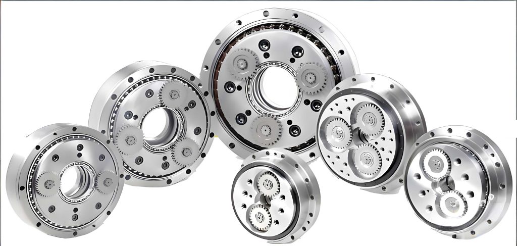
The primary components include the input sun gear, multiple planetary gears (mounted on crankshafts), cycloid discs, a stationary pinwheel (or needle gear), and the output flange. The crankshafts serve as the planetary carrier for the first stage and the input eccentrics for the second stage. Understanding the kinematic relationships between these components is the first step toward dynamic modeling.
Kinematic Analysis and Transmission Ratio Derivation
A clear derivation of the transmission ratio is foundational for constructing an accurate bond graph model. Consider the simplified kinematic diagram. Let \( \omega_1 \), \( \omega_2 \), and \( \omega_W \) represent the angular velocities of the sun gear, a planetary gear, and the output flange (which acts as the carrier for the first stage and the output for the second), respectively. Let \( z_1 \), \( z_2 \), \( z_4 \), and \( z_5 \) be the number of teeth for the sun gear, planetary gear, cycloid disc, and stationary pinwheel, respectively. The gear meshes are assumed ideal.
At the mesh point A between the sun and a planetary gear, the linear velocities must be equal. For the sun gear:
$$ v_{1A} = \omega_1 r_1 $$
where \( r_1 \) is the pitch radius of the sun gear.
For the planetary gear, its motion is a combination of rotation about its own axis and revolution with the carrier (output flange). Therefore, the velocity at point A is:
$$ v_{2A} = \omega_2 r_2 + \omega_W r_W = \omega_2 r_2 + \omega_W r_1 $$
where \( r_2 \) is the pitch radius of the planetary gear and \( r_W = r_1 \). Equating \( v_{1A} = v_{2A} \) gives the first fundamental kinematic relation:
$$ \omega_1 r_1 = \omega_2 r_2 + \omega_W r_1 \tag{1} $$
or, in terms of tooth numbers (since \( r \propto z \)):
$$ \omega_1 z_1 = \omega_2 z_2 + \omega_W z_1 \tag{1a} $$
The second stage, the cycloidal drive, is a negative-type planetary gear train. Applying the relative velocity method (inverting the entire mechanism by applying \(-\omega_W\)) simplifies it to an equivalent fixed-axis transmission. In this inverted frame, the relationship between the angular velocity of the planetary gear/crank (\( \omega_2 \)) and the output flange (\( \omega_W \)) is governed by the cycloid-pinwheel mesh. The standard formula for this “gear” pair is:
$$ \frac{\omega_2}{\omega_W} = \frac{z_5}{z_5 – z_4} \tag{2} $$
This is a critical relationship linking the two stages of the RV reducer.
Substituting Equation (2) into Equation (1a) allows us to solve for the overall reduction ratio \( i = \omega_1 / \omega_W \):
$$ \omega_1 z_1 = \left( \frac{z_5}{z_5 – z_4} \omega_W \right) z_2 + \omega_W z_1 $$
$$ \omega_1 z_1 = \omega_W \left( z_1 + z_2 \cdot \frac{z_5}{z_5 – z_4} \right) $$
Therefore, the transmission ratio of the RV reducer is:
$$ i = \frac{\omega_1}{\omega_W} = 1 + \frac{z_2}{z_1} \cdot \frac{z_5}{z_5 – z_4} \tag{3} $$
This equation confirms the high-ratio capability of the RV reducer, as it is the product of the first-stage planetary ratio \( (1 + z_2/z_1) \) and the second-stage cycloidal ratio \( (z_5/(z_5 – z_4)) \).
Fundamentals of Power Bond Graph Theory for Mechanical Systems
Bond graph theory is a domain-independent graphical modeling language for dynamic systems. It represents the flow and storage of energy between system components using power bonds. Each bond carries two variables: effort (e) and flow (f), whose product is instantaneous power. For mechanical rotational systems, effort is torque (N·m) and flow is angular velocity (rad/s). The basic elements used to model an RV reducer are:
- I-element (Inertia): Represents rotational inertia. Its constitutive relation is \( \omega = p / I \), where \( p \) is angular momentum (\( p = \int \tau \, dt \)) and \( I \) is the moment of inertia (kg·m²).
- C-element (Compliance): Represents torsional or mesh stiffness. Its linear constitutive relation is \( \tau = (1/C) \cdot \theta \), where \( \theta \) is angular deflection (rad) and \( C \) is compliance (rad/N·m), the inverse of stiffness \( k \).
- R-element (Resistance): Represents damping or friction losses. Its linear constitutive relation is \( \tau = R \cdot \omega \), where \( R \) is the rotational damping coefficient (N·m·s/rad).
- TF-element (Transformer): Represents ideal energy-conserving transformations where effort and flow are scaled. For a gear pair with radius ratio \( r \), the relations are \( \tau_{in} = r \cdot \tau_{out} \) and \( \omega_{out} = r \cdot \omega_{in} \).
- 0-junction (Common Effort): A point where efforts are equal (e.g., torque on a rigid shaft), and the sum of flows is zero. Represents a series connection.
- 1-junction (Common Flow): A point where flows are equal (e.g., angular velocity of a rigid body), and the sum of efforts is zero. Represents a parallel connection.
Applying these elements to the RV reducer involves identifying energy storage (inertias, compliances), energy dissipation (damping), and transformative coupling (gear meshes, kinematic constraints).
Bond Graph Model Development for a Single-Loop RV Reducer
For clarity, we first develop a bond graph model for a single planetary loop of the RV reducer. This model captures the essential dynamics. The corresponding bond graph is constructed by tracing the power flow from the input source to the output load.
The model incorporates the following physical phenomena specific to the RV reducer:
- Gear Mesh Stiffness (C-element): The compliance at both the sun-planet and cycloid-pinwheel meshes is modeled. For two meshing gears with individual stiffnesses \( k_1 \) and \( k_2 \), the effective mesh stiffness \( k_{mesh} \) is approximately that of springs in series:
$$ k_{mesh} = \frac{k_1 k_2}{k_1 + k_2} $$
The corresponding bond graph compliance is \( C_{mesh} = 1/k_{mesh} \). - Shaft Torsional Stiffness (C-element): The compliance of the crankshaft connecting the planetary gear to the cycloid disc is considered. The torsional stiffness \( K_{\theta} \) for a cylindrical shaft of length \( l \), shear modulus \( G \), and polar moment of inertia \( J \) is:
$$ K_{\theta} = \frac{GJ}{l} $$ - Mesh Damping (R-element): Empirical formulas are often used for gear mesh damping. A common form is:
$$ c_m = 2 \xi \sqrt{k_{mesh} \frac{I_p I_g}{I_p r_g^2 + I_g r_p^2}} $$
where \( \xi \) is the mesh damping ratio (typically 0.03-0.17), \( I_p, I_g \) are the moments of inertia, and \( r_p, r_g \) are the base circle radii of the driving and driven gears. - Kinematic Transformers (TF-elements): The sun-planet mesh and the planet-carrier kinematics are modeled using TF elements with moduli equal to the respective pitch radii ratios, effectively implementing Equations (1) and (2).
The parameters for a sample RV reducer design are summarized in the table below. These parameters are essential for performing a quantitative simulation.
| Parameter | Symbol | Value | Parameter | Symbol | Value |
|---|---|---|---|---|---|
| Sun Gear Teeth | \( z_1 \) | 12 | Pinwheel Pitch Radius | \( r_b \) | 60 mm |
| Planet Gear Teeth | \( z_2 \) | 36 | Cycloid Pitch Radius | \( r_g \) | 58.5 mm |
| Cycloid Disc Teeth | \( z_4 \) | 39 | Center Distance (Stage 1) | \( a_z \) | 42 mm |
| Pinwheel Teeth | \( z_5 \) | 40 | Sun Gear Pitch Diameter | \( d_1 \) | 21 mm |
| Module (Stage 1) | \( m \) | 1.75 mm | Planet Gear Pitch Diameter | \( d_2 \) | 63 mm |
| Eccentricity | \( a \) | 1.5 mm | Sun Gear Inertia | \( I_1 \) | 0.32e-3 kg·m² |
| Theoretical Ratio (Eq. 3) | \( i \) | 121 | Planet Gear Inertia | \( I_2 \) | 3.89e-3 kg·m² |
The corresponding bond graph element parameters, derived from the physical parameters above and material properties, are listed below. These are the direct inputs for the simulation model.
| Bond Graph Element | Symbol | Parameter | Value |
|---|---|---|---|
| TF (Sun-Planet Radius) | TF | \( r \) | 10.5 (ratio) |
| TF (Carrier Radius) | TF_1 | \( r_1 \) | 0.0317 m |
| TF (Sun Radius) | TF_2 | \( r_2 \) | 0.0952 m |
| C (Mesh Stiffness) | C | Compliance \( C \) | 1/(1.822e5) m/N |
| C (Shaft Stiffness) | C_1 | Compliance \( C_1 \) | 1/(4.2e5) m/N |
| R (Mesh Damping) | R | Damping \( R \) | 0.1 N·m·s/rad |
| R (Shaft/Carrier Damping) | R_1 | Damping \( R_1 \) | 0.5 N·m·s/rad |
| I (Planet & Crank Inertia) | I | Inertia \( I \) | 3.89e-3 kg·m² |
| Source of Flow (Input Speed) | Sf | Speed \( \omega_{in} \) | 3000 rpm (314.16 rad/s) |
Full Multi-Planet RV Reducer Model and Simulation
A realistic RV reducer employs multiple planetary gears (typically 2 or 3) to improve load distribution, balance forces, and increase torque capacity. The full bond graph model is an extension of the single-loop model, incorporating parallel power paths for each planetary unit. These paths converge at the common output flange (1-junction representing common angular velocity) and share the same input sun gear (0-junction representing common torque distribution). This parallel structure is key to the compactness and high stiffness of the RV reducer. The bond graph for the full system effectively becomes three single-loop models connected in parallel at the input and output junctions.
Using the 20-sim simulation software, the dynamic response of the RV reducer model to a step input (instantaneous application of 3000 rpm at the sun gear) is analyzed. The primary output of interest is the angular velocity of the output flange. The simulation for the single-loop model with baseline damping parameters (R=0.1, R_1=0.5) reveals a significant dynamic characteristic: a pronounced overshoot in the output speed at the onset of motion. This transient overshoot, caused by the interplay of inertias and compliances in the system, implies high instantaneous torque loads on the gear teeth, which can lead to increased stress, vibration, and accelerated wear. This highlights the critical need for dynamic analysis in the design phase of an RV reducer.
The influence of damping on this dynamic response is investigated parametrically. Increasing the damping associated with the second-stage power path (parameter R_1, representing damping in the crankshaft-cycloid-flange assembly) from 0.5 to 1.0 N·m·s/rad results in a markedly improved response. The overshoot is significantly suppressed, leading to a smoother, faster settling to the steady-state speed. This demonstrates that the dynamic performance of the RV reducer is highly sensitive to the damping characteristics of its internal components.
Conversely, the effect of the first-stage mesh damping (parameter R) is also examined. Keeping R_1 at 1.0 but reducing the mesh damping R to 0.2 N·m·s/rad reintroduces a noticeable, albeit smaller, overshoot and oscillation. This comparative analysis yields a crucial design insight: the dynamic performance of the RV reducer is more effectively controlled by increasing the damping in the second-stage (cycloidal) power transmission path rather than in the first-stage (involute gear) mesh. This is likely due to the higher inertial and compliant energies involved in the motion of the cycloid discs and the output flange. Therefore, design efforts aimed at improving the dynamic smoothness of an RV reducer—reducing start-up shock and vibration—should prioritize incorporating or enhancing damping mechanisms within the crankshaft bearings, cycloid-pinwheel contacts, or output support bearings.
Design Implications and Concluding Analysis
The bond graph modeling approach provides a powerful and efficient framework for the dynamic analysis of complex transmission systems like the RV reducer. Its energy-based methodology offers clarity in visualizing power flow and identifying critical dynamic interactions between components. The key outcomes and design guidelines derived from this analysis are summarized as follows:
- Transmission Ratio Confirmation: The kinematic derivation confirms the compound nature of the RV reducer’s ratio, as given by Equation (3). This formula is essential for initial sizing but does not account for dynamic effects.
- Parameterized Dynamic Model: The bond graph model successfully integrates stiffness, damping, and inertia effects for both transmission stages. The parameters in Table 2 serve as a template for populating models of specific RV reducer designs.
- Critical Role of Damping: Simulation results unequivocally show that damping is a critical design parameter, not just a loss factor. Properly tuned damping is essential for mitigating undesirable transient responses.
- Stage-Specific Design Strategy: A major finding is the differentiated impact of damping. To optimize the dynamic response of an RV reducer:
- Focus on Second-Stage Damping: Design choices that increase damping in the cycloidal drive path (e.g., optimized bearing preload, material selection for pins/cycloid disc, potential for fluid damping) will most effectively reduce start-up overshoot and transient vibrations.
- First-Stage Damping is Less Critical: While necessary for realism, overly increasing damping in the involute gear mesh has a less pronounced effect on suppressing the primary transient and may unnecessarily increase losses.
- Predictive Design Tool: The established model allows for rapid simulation of design changes (e.g., varying stiffness, inertia, damping) before detailed CAD or prototyping, accelerating the development cycle and improving first-pass design quality.
In conclusion, the inherent complexity of the RV reducer necessitates advanced dynamic analysis tools during its design phase. The Power Bond Graph method, as demonstrated, provides an elegant and effective solution. It bridges the gap between high-level system understanding and detailed simulation, enabling designers to proactively address dynamic performance issues. By applying this methodology, engineers can make informed decisions about parameter selection, particularly regarding damping distribution, leading to the development of RV reducers with superior smoothness, lower noise, higher reliability, and longer service life—all of which are critical for high-performance robotic and precision automation applications. The insights gained, especially the prioritization of second-stage damping, offer a clear and actionable guideline for enhancing the dynamic design of future RV reducer iterations.