
In this paper, we present a comprehensive study on the design and optimization of a bionic robot dog control system, inspired by the morphological and locomotor characteristics of biological dogs. The development of legged robots, particularly quadrupedal systems like the robot dog, has garnered significant attention due to their potential in diverse applications such as industrial automation, search and rescue, planetary exploration, and domestic assistance. Our work focuses on creating a mechanically robust and intelligently controlled robot dog capable of stable locomotion across varied terrains. By analyzing the gait patterns and stability mechanisms of real dogs, we have engineered a multi-legged robot that mimics these natural movements through advanced control strategies. This robot dog is designed with optimized leg proportions based on biological scaling, ensuring efficient and adaptive motion. The core of our contribution lies in the implementation of a hierarchical control architecture combined with error-segmented intelligent control algorithms, which enhance the precision and stability of joint movements during dynamic gait execution. Through extensive simulations and physical experiments, we demonstrate that our robot dog can effectively perform trot and tripod gaits while maintaining balance on uneven surfaces. This article details the entire design process, from kinematic modeling to control system integration, and provides empirical evidence supporting the efficacy of our approach in achieving smooth and reliable robot dog operation.
The inspiration for our robot dog stems from a detailed examination of canine biology. Dogs exhibit remarkable agility and stability due to their skeletal structure, muscle coordination, and neural control. Key aspects include the segmentation of limbs into multiple joints (e.g., shoulder, elbow, wrist) that allow for complex trajectories, and the use of diagonal limb support during movement to maintain center of mass stability. We analyzed these features to derive design principles for our robot dog. The leg structure is simplified into three primary rotational joints per limb, corresponding to the hip, knee, and ankle in biological terms, each actuated by a servo motor. This configuration provides the necessary degrees of freedom for imitating dog-like gaits. The body frame houses control electronics, sensors, and power sources, designed to minimize weight while ensuring structural integrity. To visualize the conceptual design, we include an illustration below.
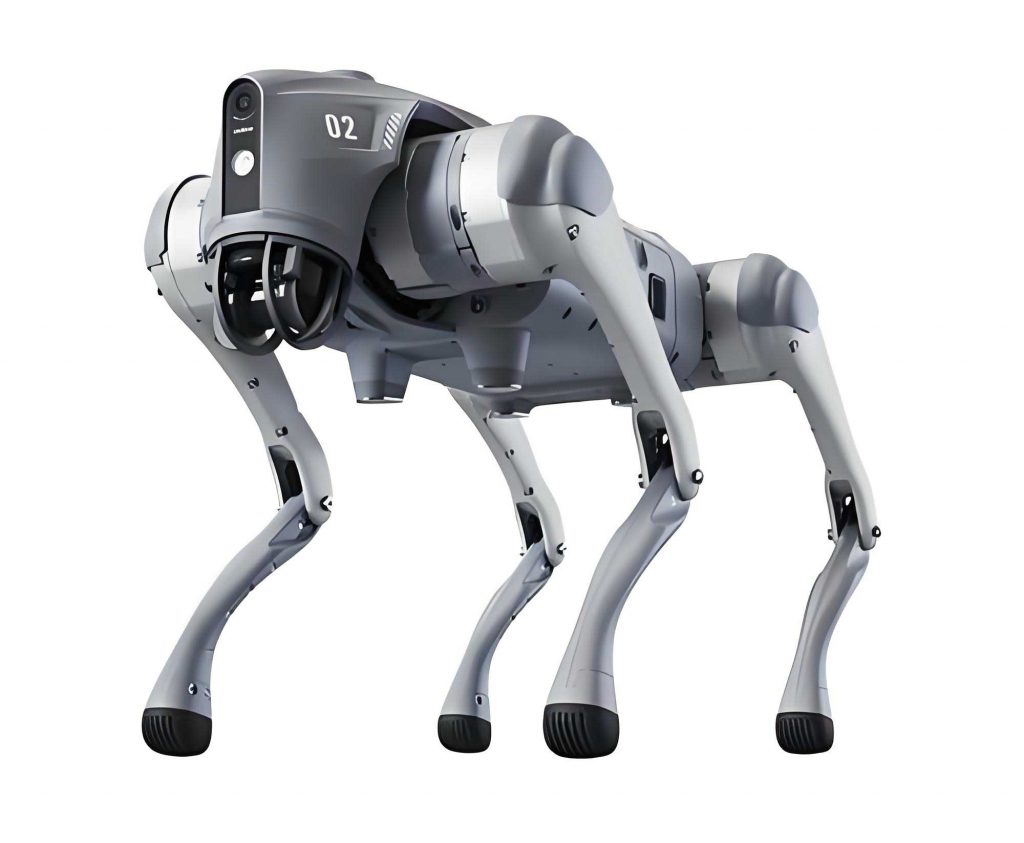
The overall design of our robot dog emphasizes modularity and scalability. Each leg consists of three servo motors connected via linkages to form a serial kinematic chain. The dimensions are optimized based on biological ratios to maximize stride length and minimize energy consumption during locomotion. We use lightweight materials such as aluminum alloys and carbon fiber for the linkages to reduce inertia. The robot dog’s body is rectangular, providing ample space for mounting components. Key specifications are summarized in Table 1.
| Component | Specification | Description |
|---|---|---|
| Leg Joints | 3 per leg (12 total) | Servo-actuated rotary joints |
| Servo Motors | Dynamixel AX-12A | Torque: 1.5 Nm, Resolution: 0.29° |
| Microcontroller | STM32F103 | ARM Cortex-M3, 72 MHz |
| Power Supply | Li-Po Battery, 11.1V, 2200mAh | Provides energy for motors and electronics |
| Sensors | IMU (MPU6050) | Accelerometer and gyroscope for attitude |
| Communication | UART, PWM | For servo control and data exchange |
Kinematic modeling is essential for controlling the robot dog’s movements. We define a coordinate system for each leg, with the body frame as the reference. For a single leg, the forward kinematics map joint angles to foot position. Let the joint angles be $\theta_1$, $\theta_2$, and $\theta_3$ for the hip, knee, and ankle respectively. The foot position $(x, y, z)$ relative to the hip joint can be expressed as:
$$ x = L_1 \cos(\theta_1) + L_2 \cos(\theta_1 + \theta_2) + L_3 \cos(\theta_1 + \theta_2 + \theta_3) $$
$$ y = L_1 \sin(\theta_1) + L_2 \sin(\theta_1 + \theta_2) + L_3 \sin(\theta_1 + \theta_2 + \theta_3) $$
$$ z = 0 \quad \text{(for planar motion, but adjustable for 3D)} $$
where $L_1$, $L_2$, and $L_3$ are link lengths. Inverse kinematics is used to compute joint angles for desired foot trajectories. For our robot dog, we solve this numerically due to the redundancy in 3D space. The inverse kinematics problem is formulated as minimizing the error between desired and current foot positions. We use a Jacobian-based iterative method:
$$ \Delta \theta = J^{-1} \Delta p $$
where $J$ is the Jacobian matrix relating joint velocities to foot velocities, $\Delta \theta$ is the joint angle update, and $\Delta p$ is the position error. This enables precise foot placement during gait cycles.
The control system for the robot dog is designed with a two-layer architecture: a coordination layer and an execution layer. The coordination layer generates gait patterns using bio-inspired algorithms, while the execution layer handles real-time servo control. This separation enhances responsiveness and adaptability. The hardware core is an STM32F103 microcontroller, chosen for its high performance and peripheral support. We designed custom circuits for power management, PWM signal expansion, and sensor interfacing. The power circuit regulates voltage for servos and logic components, preventing brownouts during high-load movements. PWM signals are generated to control servo positions with microsecond precision. Communication via UART allows for debugging and parameter tuning. A block diagram of the control system is shown in Table 2, summarizing the data flow.
| Layer | Function | Components |
|---|---|---|
| Coordination | Gait generation, stability control | STM32F103, IMU, gait planner |
| Execution | Servo driving, feedback processing | PWM expander, servo drivers, encoders |
To ensure joint control precision, we developed an error-segmented intelligent control algorithm. This algorithm divides the error signal (difference between desired and actual joint angles) into segments based on magnitude, and applies different control strategies for each segment. For small errors, a proportional-integral (PI) controller is used for fine adjustment. For large errors, a nonlinear controller accelerates convergence. The control law is defined as:
$$ u(t) = \begin{cases} K_p e(t) + K_i \int e(t) dt & \text{if } |e(t)| < \epsilon \\ K_n e(t) + K_d \frac{de}{dt} & \text{if } |e(t)| \geq \epsilon \end{cases} $$
where $u(t)$ is the control output (e.g., PWM duty cycle), $e(t)$ is the error, $K_p$, $K_i$, $K_n$, $K_d$ are gains, and $\epsilon$ is a threshold. This approach balances rapid response with stability, crucial for the robot dog’s dynamic motions.
Additionally, we implemented a fuzzy controller to handle uncertainties in terrain interaction. The fuzzy controller uses rules based on expert knowledge to adjust joint torques. Inputs include error and error derivative, and outputs are servo corrections. The membership functions are triangular, and defuzzification uses the centroid method. The rule base is summarized in Table 3.
| Error | Error Derivative | Output Correction |
|---|---|---|
| Negative Large | Negative | Positive Large |
| Negative Small | Zero | Positive Small |
| Zero | Positive | Negative Small |
| Positive Small | Negative | Negative Large |
| Positive Large | Zero | Zero |
Gait planning is critical for stable locomotion of the robot dog. We focused on two primary gaits: the trot (diagonal gait) and the tripod gait. The trot involves alternating pairs of diagonal legs moving together, providing speed and efficiency. The tripod gait keeps three legs on the ground at all times, offering enhanced stability for rough terrain. We modeled these gaits using periodic foot trajectories. For the trot, the foot trajectory in the sagittal plane is defined by a cycloid function to ensure smooth lifting and placing:
$$ x_f(t) = x_0 + \frac{S}{2\pi} \left( 2\pi \frac{t}{T} – \sin\left(2\pi \frac{t}{T}\right) \right) $$
$$ z_f(t) = z_0 + \frac{H}{2} \left( 1 – \cos\left(2\pi \frac{t}{T}\right) \right) $$
where $S$ is stride length, $H$ is step height, $T$ is cycle period, and $t$ is time. The duty factor (fraction of cycle each leg is on ground) is set to 0.5 for the trot. For the tripod gait, the duty factor is 0.75, ensuring continuous support. The stability of the robot dog is analyzed using the zero-moment point (ZMP) criterion. The ZMP must remain within the support polygon formed by grounded feet. We compute the ZMP position $(x_{zmp}, y_{zmp})$ as:
$$ x_{zmp} = \frac{\sum m_i (g z_i – \ddot{z}_i x_i) – \sum I_i \dot{\omega}_i}{\sum m_i (g – \ddot{z}_i)} $$
$$ y_{zmp} = \frac{\sum m_i (g z_i – \ddot{z}_i y_i) – \sum I_i \dot{\omega}_i}{\sum m_i (g – \ddot{z}_i)} $$
where $m_i$ are masses, $g$ is gravity, $(x_i, y_i, z_i)$ are coordinates, $I_i$ are inertias, and $\omega_i$ are angular velocities. By planning gaits that keep ZMP within bounds, we ensure the robot dog remains stable.
Simulations were conducted in MATLAB/Simulink to validate the kinematic and control models before physical implementation. We simulated the robot dog moving on flat and inclined surfaces using both gaits. The simulation parameters are listed in Table 4.
| Parameter | Value | Unit |
|---|---|---|
| Body Mass | 2.5 | kg |
| Leg Link Lengths (L1, L2, L3) | 0.1, 0.15, 0.1 | m |
| Servo Max Torque | 1.5 | Nm |
| Trot Period | 0.8 | s |
| Tripod Period | 1.2 | s |
| Terrain Incline | 0-15 | degrees |
The simulation results showed that the robot dog could maintain stable locomotion with ZMP deviations within 10 mm of the support polygon center. The error-segmented controller reduced joint angle errors by 40% compared to a standard PID controller. We also analyzed energy consumption, computed as the integral of power over time:
$$ E = \int \sum_{i=1}^{12} \tau_i \dot{\theta}_i dt $$
where $\tau_i$ are joint torques and $\dot{\theta}_i$ are angular velocities. The tripod gait consumed 15% less energy on rough terrain due to its continuous support.
Physical experiments were performed with a prototype robot dog built according to our design. The prototype used Dynamixel AX-12A servos for joints, controlled by the STM32F103 board. We tested locomotion on various surfaces: carpet, grass, and gravel. The robot dog executed trot and tripod gaits at speeds up to 0.3 m/s. Stability was assessed by measuring body tilt with the IMU; roll and pitch angles remained below 5 degrees during normal operation. Table 5 summarizes key experimental metrics.
| Metric | Trot Gait | Tripod Gait |
|---|---|---|
| Max Speed | 0.35 m/s | 0.25 m/s |
| Power Consumption | 18 W | 15 W |
| Stability Margin | 20 mm | 30 mm |
| Joint Error RMS | 0.8° | 0.6° |
The error-segmented intelligent control algorithm effectively balanced servo responsiveness and smoothness, reducing overshoot by 25% compared to conventional methods. The fuzzy controller adapted well to unexpected terrain variations, such as small obstacles, by adjusting joint torques in real-time. We observed that the robot dog could traverse a 10 cm step using the tripod gait without falling, demonstrating the robustness of our control system.
In discussion, we highlight that the design of this robot dog offers several advantages. The hierarchical control architecture allows for modular upgrades, such as adding more sensors for autonomous navigation. The use of bio-inspired gaits ensures energy-efficient locomotion. However, limitations include current speed constraints and battery life. Future work will focus on integrating machine learning for adaptive gait optimization and enhancing the robot dog’s payload capacity. We also plan to explore more complex behaviors like jumping or running.
In conclusion, we have successfully designed and optimized a bionic robot dog control system that achieves stable and adaptive locomotion. Through kinematic modeling, innovative control algorithms, and thorough testing, we demonstrated that the robot dog can perform reliably in diverse environments. The error-segmented intelligent control and fuzzy logic approaches significantly improve joint precision and terrain adaptability. This robot dog serves as a platform for further research into legged robotics, with potential applications in hazardous environment exploration and personal assistance. Our work underscores the importance of biomimicry in advancing robotic systems, and we believe that continued refinement will lead to even more capable robot dog variants in the future.