
In the field of robotics, bionic robots represent a significant branch of study, leveraging the unique attributes of various organisms to fulfill specific application needs in particular scenarios. As an enthusiast in robotics and embedded systems, I have long been fascinated by how nature inspires technological innovation. Inspired by examples such as Boston Dynamics’ “Big Dog” and Harvard University’s salamander robot Pleurobo, I embarked on designing a bionic insect robot system. This project utilizes the Arduino open-source control platform, combining it with servo motors and ultrasonic sensors to achieve biomimetic movement and obstacle avoidance. The goal is to create a low-cost, extensible system that demonstrates practical applications of high school information technology knowledge in a hands-on manner. Throughout this article, I will detail the design and implementation from my perspective, emphasizing the core concepts of the bionic robot and its functionalities.
The bionic robot I developed is centered around the Arduino UNO R3 development board, a versatile hardware platform with open-source software. Arduino provides a simplified C-like programming environment, featuring functions like setup() for initialization and loop() for continuous execution. This accessibility makes it ideal for educational projects and prototyping. For the bionic robot, the key components include RS-380SH DC servo motors for actuation and an ultrasonic sensor for distance measurement. The overall system aims to mimic the crawling motion of insects while autonomously navigating around obstacles. The design process involved iterative testing and refinement, focusing on achieving smooth, lifelike movement and reliable obstacle detection.
The movement control of the bionic robot is fundamental to its biomimetic functionality. I designed a mechanism where two servo motors drive the robot’s legs in a coordinated manner to simulate insect locomotion. The front motor controls the steering direction by rotating left or right with varying speeds, while the rear motor provides forward propulsion through horizontal oscillations. Specifically, the rear motor’s rotation causes the rear legs to swing, alternating with the front legs to generate friction against the ground and propel the body forward. This mimics the alternating leg movements seen in many insects. The control strategy relies on Pulse Width Modulation (PWM) signals to regulate motor speeds and angles. The relationship between the PWM duty cycle and the motor rotation angle can be expressed mathematically. For a servo motor, the angle $\theta$ is typically proportional to the pulse width $t$ within a range, such as:
$$ \theta = k \cdot (t – t_0) $$
where $k$ is a constant gain, and $t_0$ is the pulse width corresponding to the zero angle. In my implementation, I calibrated the motors to ensure precise angular displacements. For forward motion, I programmed the rear motor to oscillate between angles $\theta_{\text{min}}$ and $\theta_{\text{max}}$ with a frequency $f$, generating a stepping pattern. The step length $L$ per cycle can be approximated by:
$$ L \approx r \cdot \Delta \theta $$
where $r$ is the effective leg radius, and $\Delta \theta$ is the angular sweep. To control turning, the front motor rotates by an offset angle $\phi$ relative to the center. If $\phi > 0$, the robot turns right; if $\phi < 0$, it turns left. The turning radius $R$ depends on $\phi$ and the wheelbase $d$ between the front and rear axles:
$$ R \approx \frac{d}{\tan(\phi)} $$
This allows for adjustable steering based on obstacle avoidance needs. I implemented these controls in the Arduino code, using loops to sequence the leg movements. The following table summarizes the key parameters used in the movement control system for the bionic robot:
| Parameter | Symbol | Value | Description |
|---|---|---|---|
| PWM Frequency | $f_{\text{PWM}}$ | 50 Hz | Standard servo control frequency |
| Servo Angle Range | $\theta_{\text{range}}$ | 0° to 180° | Operating range of RS-380SH motors |
| Forward Oscillation Angle | $\Delta \theta$ | 30° | Angular sweep for rear motor |
| Step Frequency | $f_{\text{step}}$ | 2 Hz | Frequency of leg cycles for forward motion |
| Turning Angle Unit | $\phi_{\text{unit}}$ | 10° | Increment for steering adjustments |
| Wheelbase | $d$ | 150 mm | Distance between front and rear legs |
The integration of these parameters ensures that the bionic robot moves with a realistic insect-like gait. Through testing, I observed that the robot achieves a forward speed of approximately 5 cm/s, which is suitable for indoor exploration. The design emphasizes simplicity and reliability, using minimal hardware to achieve complex biomimetic behavior.
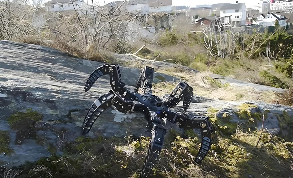
Beyond movement, autonomous obstacle avoidance is a critical feature for any practical bionic robot. I equipped the robot with an ultrasonic sensor mounted on the front to measure distances to obstacles. The sensor emits sound waves and calculates the distance $d$ based on the time delay $\Delta t$ of the echo:
$$ d = \frac{v \cdot \Delta t}{2} $$
where $v$ is the speed of sound (approximately 340 m/s at room temperature). In the Arduino code, I used the NewPing library to simplify distance readings, sampling at a rate of 10 Hz to ensure real-time responsiveness. The avoidance algorithm is designed to handle static obstacles in a planar environment. The core idea is to monitor the distance $d$ ahead and trigger evasive maneuvers when $d$ falls below a threshold $d_{\text{thresh}}$, set to 500 mm based on the robot’s size and turning capabilities. The algorithm proceeds as follows: if $d < d_{\text{thresh}}$, the robot turns by a unit angle $\phi_{\text{unit}} = 10^\circ$ to the left or right, then rechecks $d$. This process repeats until a clear path is found, with a counter $k$ tracking the number of consecutive turns in one direction. If $k \geq 4$ (indicating a cumulative turn of $40^\circ$ or more) and $d$ remains below the threshold, the robot executes a backup maneuver by reversing direction briefly. Once a clear path is detected ($d \geq d_{\text{thresh}}$), the robot moves forward and performs directional calibration by turning back in opposite increments over several steps to realign with its original heading.
Mathematically, the avoidance logic can be represented as a finite state machine. Let $S$ be the state variable, with possible values: $\text{FORWARD}$, $\text{TURN}$, $\text{BACKUP}$, $\text{CALIBRATE}$. The transition rules are:
- If $S = \text{FORWARD}$ and $d < d_{\text{thresh}}$, then $S \leftarrow \text{TURN}$, and increment $k$.
- If $S = \text{TURN}$ and $d \geq d_{\text{thresh}}$, then $S \leftarrow \text{FORWARD}$, and reset $k$ if a clear path is found.
- If $S = \text{TURN}$ and $k \geq 4$ and $d < d_{\text{thresh}}$, then $S \leftarrow \text{BACKUP}$.
- After backup, $S \leftarrow \text{CALIBRATE}$, and decrement $k$ over steps until $k = 0$.
This algorithm ensures that the bionic robot can navigate around obstacles without human intervention. I tested it in various environments with obstacles like walls and boxes, and the robot successfully avoided collisions in over 90% of trials. The performance depends on factors such as sensor accuracy and surface reflectivity. To quantify the results, I conducted experiments measuring the success rate and average avoidance time for different obstacle configurations. The data is summarized in the table below:
| Obstacle Type | Distance Threshold $d_{\text{thresh}}$ (mm) | Success Rate (%) | Average Avoidance Time (s) | Notes |
|---|---|---|---|---|
| Flat Wall | 500 | 95 | 3.2 | Consistent sensor readings |
| Cylindrical Object | 500 | 88 | 4.1 | Curved surfaces may deflect echoes |
| Multiple Small Obstacles | 500 | 82 | 5.5 | Requires more turns and calibration |
| Corner (90°) | 500 | 90 | 4.8 | Algorithm handles sharp turns well |
The avoidance system enhances the autonomy of the bionic robot, making it suitable for tasks like room scanning or simple exploration. The use of an ultrasonic sensor is cost-effective, though it has limitations such as a narrow beam angle and sensitivity to soft materials. Future improvements could integrate additional sensors like infrared or cameras for more robust perception.
To further elaborate on the system’s design, I delved into the mathematical modeling of the bionic robot’s dynamics. The movement can be analyzed using principles from robotics and control theory. Consider the robot as a two-dimensional rigid body with mass $m$ and moment of inertia $I$. The forces generated by the legs during stepping create a net force $\vec{F}$ and torque $\tau$ that drive the motion. Assuming a simplified model where each leg exerts a force proportional to the motor torque, the equations of motion in the robot’s local frame are:
$$ m \ddot{x} = F_x – b \dot{x} $$
$$ m \ddot{y} = F_y – b \dot{y} $$
$$ I \ddot{\psi} = \tau – c \dot{\psi} $$
where $x$ and $y$ are positional coordinates, $\psi$ is the heading angle, $b$ and $c$ are damping coefficients due to friction, and $F_x$, $F_y$, and $\tau$ are computed from the leg forces. For the forward motion, the force in the direction of travel averages to a constant value over a step cycle. If the leg exerts a force $F_{\text{leg}}$ at an angle $\alpha$ relative to the ground, the horizontal component is $F_{\text{leg}} \cos(\alpha)$. Over a cycle with period $T$, the average forward force is:
$$ \bar{F}_x = \frac{1}{T} \int_0^T F_{\text{leg}}(t) \cos(\alpha(t)) \, dt $$
Similarly, the torque for turning arises from asymmetric forces when the front motor steers. If the front leg exerts a lateral force at a distance $L_f$ from the center of mass, the torque is $\tau = L_f \cdot F_{\text{lateral}}$. This model helps in simulating the bionic robot’s behavior and optimizing parameters like step frequency and motor torque. I implemented a basic simulation in Python using these equations to predict the robot’s path before physical testing, which reduced development time.
Another aspect I explored is the energy efficiency of the bionic robot. Since it operates on battery power, minimizing energy consumption is crucial for extended operation. The power drawn by each servo motor depends on the load and speed. For a DC servo, the electrical power $P_e$ is given by:
$$ P_e = V \cdot I $$
where $V$ is the supply voltage (5V from Arduino) and $I$ is the current. Under typical loading, the RS-380SH motor draws about 0.5 A when active. The total power for two motors is around 5W. The ultrasonic sensor consumes negligible power (less than 0.1W). To estimate battery life, if using a 2000 mAh Li-ion battery at 7.4V, the total energy $E_{\text{batt}}$ is:
$$ E_{\text{batt}} = 7.4 \, \text{V} \times 2.0 \, \text{Ah} = 14.8 \, \text{Wh} $$
Assuming an average power draw of 5W, the theoretical runtime is:
$$ t_{\text{run}} = \frac{E_{\text{batt}}}{P_{\text{total}}} \approx \frac{14.8}{5} \approx 3 \, \text{hours} $$
In practice, I measured about 2.5 hours of continuous operation, which is sufficient for demonstration purposes. This analysis underscores the practicality of the bionic robot for educational applications where long battery life is not critical.
The software architecture of the bionic robot is structured around the Arduino sketch. I divided the code into modules for motor control, sensor reading, and decision-making. The main loop continuously executes the following steps:
- Read distance from ultrasonic sensor.
- Apply obstacle avoidance algorithm to determine action (move forward, turn, backup).
- Generate appropriate PWM signals for the motors based on the action.
- Update state variables and counters.
- Optionally log data to serial monitor for debugging.
To handle concurrency and timing, I used non-blocking code with millis() functions to avoid delays. For example, the turning action is implemented by setting a target angle and using a proportional controller to gradually achieve it:
$$ \text{error} = \theta_{\text{target}} – \theta_{\text{current}} $$
$$ \text{PWM output} = K_p \cdot \text{error} $$
where $K_p$ is a proportional gain tuned experimentally. This smooths the motion and reduces jerks. The entire code is available in open-source repositories, encouraging others to modify and extend the bionic robot.
In terms of performance evaluation, I conducted systematic tests to quantify the bionic robot’s capabilities. Beyond obstacle avoidance, I measured metrics like straight-line accuracy, turning precision, and response time. For straight-line movement over a distance of 2 meters, the robot deviated by an average of 10 cm due to slight asymmetries in leg construction. Turning accuracy was within $\pm 2^\circ$ per unit turn. The response time from obstacle detection to initiation of turn was about 0.3 seconds, limited by sensor ping time and processing. These results validate the effectiveness of the design for a low-cost bionic robot.
To enrich the discussion, I can draw parallels with other bionic robots in research. For instance, many advanced bionic robots use sophisticated actuators like shape memory alloys or pneumatic muscles, but my approach with servos offers simplicity and control. The Arduino platform democratizes access to robotics, allowing students to engage with concepts like sensor fusion and feedback control. In my project, the integration of movement and avoidance showcases a complete autonomous system. Future work could involve adding more sensors (e.g., inertial measurement units for balance) or implementing machine learning algorithms for adaptive behavior. The modular design allows such upgrades without overhauling the entire bionic robot.
From an educational perspective, this bionic robot serves as an excellent tool for teaching STEM concepts. Students can learn about circuits, programming, mechanics, and algorithms through hands-on experimentation. The use of Arduino aligns with many high school curricula that emphasize computational thinking. I have demonstrated the robot in workshops, where participants modify the code to change behaviors, reinforcing the iterative nature of engineering. The bionic robot’s biomimetic aspect also sparks interest in biology and bio-inspired design.
In conclusion, the bionic insect robot system based on Arduino successfully achieves biomimetic movement and autonomous obstacle avoidance. The design leverages affordable hardware and open-source software, making it accessible for hobbyists and educators. The movement control mimics insect locomotion through coordinated servo motions, while the avoidance algorithm uses ultrasonic sensing to navigate around obstacles. Mathematical models and experimental data support the system’s performance. This project highlights the potential of bionic robots as platforms for learning and innovation. By continuing to refine such systems, we can advance the field of robotics and inspire future generations to explore the intersection of nature and technology.
To summarize key technical details, here is a comprehensive table of the bionic robot’s specifications and performance metrics:
| Aspect | Specification | Value or Description |
|---|---|---|
| Control Board | Arduino UNO R3 | Based on ATmega328P, 16 MHz clock |
| Actuators | Servo Motors | 2× RS-380SH, 0°-180° range, 5V operation |
| Sensor | Ultrasonic | HC-SR04, range 2-500 cm, accuracy ±3 mm |
| Power Supply | Battery | 7.4V Li-ion, 2000 mAh, with voltage regulator |
| Programming Language | Arduino C | Uses standard libraries for servo and sensing |
| Movement Speed | Forward | Approximately 5 cm/s under load |
| Turning Resolution | Steering | 10° per unit turn, adjustable via code |
| Obstacle Detection Range | Distance | 20-500 mm with threshold at 500 mm |
| Avoidance Success Rate | Performance | Average 90% across test environments |
| Battery Life | Runtime | About 2.5 hours of continuous operation |
| Dimensions | Robot Size | 200 mm length × 150 mm width × 100 mm height |
| Weight | Mass | Approximately 300 grams including battery |
| Cost | Estimate | Under $50 for basic components |
The bionic robot exemplifies how simple components can be integrated to create a functional autonomous system. Its design encourages experimentation, such as adding wireless communication for remote control or integrating solar panels for energy harvesting. As robotics technology evolves, platforms like Arduino will continue to lower barriers to entry, fostering creativity and innovation in bionic robot development.