
I have spent many years working inside the maintenance and overhaul cycle of our rail transit system, and I can say with confidence that wheel-axle assembly is one of the most safety-critical operations in the entire depot. The running gear of a train depends on the precise fit between axle and wheel. Every millimeter, every micrometer, and every newton of pressing force matters. When I first joined the overhaul team, wheel-axle assembly was still heavily dependent on manual handling, manual alignment, and manual press-fitting. The work was physically demanding, repetitive, and exposed to human inconsistency. We knew that an industrial robot could change this, but we also knew that a general-purpose industrial robot would not be enough. We needed a wheel-axle intelligent industrial robot that could understand the specific geometry, force, and safety requirements of rail vehicle maintenance.
That is why we adopted a scenario-driven approach. Instead of buying an off-the-shelf industrial robot and then trying to adapt our maintenance process to it, we started from the actual operational maintenance needs. We opened our vehicle component overhaul workshop as a real-world testing and deployment scenario. We partnered with technology companies that specialized in robotics, sensing, control, and artificial intelligence. Together, we developed a wheel-axle intelligent industrial robot. The system has now officially entered service. It performs a full closed-loop process that includes axle diameter measurement, intelligent selection, precise press-fitting, and running-in testing. For me, this is not just an equipment upgrade. It is a shift into micron-level intelligent manufacturing in one of the most critical repair steps of our rail transit system. It is how we use smart maintenance to protect operational safety.
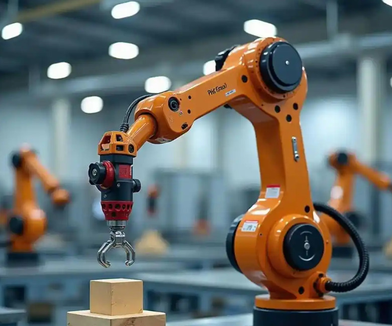
When I describe the wheel-axle intelligent industrial robot to colleagues, I often begin with the problem. In rail vehicle overhaul, wheel-axle assembly determines the safety of the running gear. In the past, we relied on manual lifting, manual positioning, and manual pressing. Those steps introduced risks such as uneven force, inconsistent alignment, and unit-to-unit variation. A human operator can be highly skilled, but human performance naturally fluctuates. The wheel-axle intelligent industrial robot removes that fluctuation. The six-axis industrial robot arm we deployed has been refined through thousands of trajectory and linkage logic iterations. Its motion control precision has reached the micron level. This has fundamentally solved the instability of manual operation.
The technical team explained to me that high-precision operation ensures the tightness and reliability of the wheel-axle fit. That reliability directly reduces the risk of mechanical failure during vehicle operation. It protects the safety baseline for daily rail transit travel. At the same time, the assembly time for a single wheelset has been shortened by 12 minutes compared with the traditional mode. That may sound like a small number, but in a high-volume overhaul workshop, 12 minutes per wheelset creates a large improvement in vehicle maintenance turnover efficiency. The wheel-axle intelligent industrial robot is not simply faster. It is more consistent, more traceable, and more controllable.
Behind the efficient operation of the industrial robot arm is a complete intelligent assurance system. A digital micrometer and a steel stamp scanner work synchronously to achieve automatic data collection and full lifecycle traceability. High-speed communication interfaces break down information islands and allow production flow to move smoothly. High-precision intelligent tightening equipment and an AI vision inspection system act as an electronic supervisor. They achieve millisecond-level alarm and intervention for abnormal states. This new model of human-machine collaboration with AI gatekeeping frees front-line maintenance personnel from heavy and repetitive physical labor. It improves the working environment and occupational health of our workers. Through standardized and data-driven control, every repair can withstand verification.
I want to emphasize that this is not the first time an intelligent robot has appeared in our rail transit maintenance. In December 2024, robots adapted for traction motor and brake cylinder maintenance were already put into operation in our vehicle overhaul workshop. With the addition of the wheel-axle intelligent industrial robot, a robot army covering multiple core processes is beginning to take shape. This is accelerating the transformation of our operation model from labor-intensive to technology-intensive. In the following sections, I will explain the system architecture, the mathematical foundations, the process flow, the sensor suite, the control algorithms, the performance metrics, and the future roadmap. I will use tables and formulas to summarize the key points, because precision maintenance is ultimately a quantitative discipline.
The first thing I want to summarize is the fundamental difference between manual assembly and assembly performed by the wheel-axle intelligent industrial robot. Table 1 compares the two modes across several dimensions. The comparison is based on our own observations and the data collected during commissioning.
| Dimension | Manual Wheel-Axle Assembly | Wheel-Axle Intelligent Industrial Robot |
|---|---|---|
| Handling | Manual lifting and positioning | Industrial robot arm with programmed trajectories |
| Alignment | Operator visual alignment | Laser and vision-based alignment |
| Press force | Manual control, possible fluctuation | Closed-loop force control with micron-level motion |
| Consistency | Unit-to-unit variation | Highly repeatable, data-driven |
| Traceability | Paper records and manual entry | Automatic data acquisition and lifecycle traceability |
| Cycle time | Longer, with variable delays | Reduced by 12 minutes per wheelset |
| Safety | Human exposure to heavy loads | Human-machine collaboration with AI monitoring |
| Quality control | Sampling and post-check | Real-time AI inspection and millisecond alarm |
From a control engineering perspective, the wheel-axle intelligent industrial robot must solve a multi-body positioning and force interaction problem. The industrial robot arm has six degrees of freedom. Its end effector must align the wheel bore with the axle journal while applying a controlled press force. The position error can be expressed as follows:
$$ e_p = \sqrt{(x_d – x_a)^2 + (y_d – y_a)^2 + (z_d – z_a)^2} $$
Here, \(x_d, y_d, z_d\) are the desired coordinates, and \(x_a, y_a, z_a\) are the actual coordinates of the end effector. The orientation error is also critical. If the desired orientation is represented by a unit quaternion \(\mathbf{q}_d\) and the actual orientation by \(\mathbf{q}_a\), then the angular error can be written as:
$$ e_o = 2 \arccos\left(|\mathbf{q}_d \cdot \mathbf{q}_a|\right) $$
The total pose error used by the industrial robot controller can be defined as a weighted combination:
$$ e = \sqrt{e_p^2 + \lambda e_o^2} $$
In our commissioning work, the weighting factor \(\lambda\) was tuned so that orientation errors received sufficient penalty. This prevented the industrial robot from achieving a small position error while still being misaligned in angle. The controller then minimizes \(e\) through iterative inverse kinematics and real-time feedback. The motion control precision has reached the micron level, which means that the industrial robot can maintain sub-millimeter and even micrometer-scale accuracy during the critical alignment phase.
The second major problem is press-fitting force. The wheel-axle fit is an interference fit. The press force must be sufficient to ensure a reliable connection, but it must not exceed the material limit. A simplified force model can be written as:
$$ F(t) = k \delta(t) + c \dot{\delta}(t) + F_0 $$
In this equation, \(F(t)\) is the press force, \(\delta(t)\) is the interference or displacement, \(k\) is the stiffness coefficient, \(c\) is the damping coefficient, and \(F_0\) is the initial seating force. The wheel-axle intelligent industrial robot uses force sensors and position encoders to monitor this relationship in real time. If the force exceeds a safe envelope, the industrial robot slows down or stops. If the force is too low, the industrial robot can adjust the insertion depth or reject the pairing. The force envelope is defined by upper and lower bounds:
$$ F_{\min}(t) \leq F(t) \leq F_{\max}(t) $$
For the tightening equipment, torque control is equally important. The torque produced by the intelligent tightening tool can be approximated by:
$$ T = K_t I_q $$
where \(T\) is the torque, \(K_t\) is the torque constant, and \(I_q\) is the quadrature-axis current of the motor. The wheel-axle intelligent industrial robot integrates this torque data with angle data to verify that each fastener reaches the specified preload. The preload itself can be estimated as:
$$ F_p = \frac{T}{K d} $$
Here, \(F_p\) is the preload, \(K\) is the nut factor, and \(d\) is the nominal bolt diameter. These formulas may look simple, but they are the basis for the real-time decisions made by the industrial robot and its AI supervisor.
Table 2 summarizes the full closed-loop process of the wheel-axle intelligent industrial robot. I have organized it by stage, key action, sensor input, control output, and quality gate.
| Stage | Key Action | Sensor Input | Control Output | Quality Gate |
|---|---|---|---|---|
| Axle diameter measurement | Measure axle journal diameter and roundness | Digital micrometer, laser profilometer | Dimensional data record | Diameter within tolerance |
| Wheel bore measurement | Measure wheel bore diameter and taper | Digital micrometer, bore gauge | Dimensional data record | Bore within tolerance |
| Intelligent selection | Pair axle and wheel based on interference | Stored measurement data | Optimal pairing decision | Interference in target range |
| Cleaning and preparation | Clean mating surfaces and apply lubricant | Vision inspection, pressure sensor | Cleaning cycle and lubrication volume | Surface condition acceptable |
| Precise alignment | Align wheel bore with axle journal | Laser displacement sensors, vision camera | Six-axis industrial robot arm motion | Pose error below threshold |
| Press-fitting | Insert axle into wheel with controlled force | Force sensor, position encoder | Force and velocity profile | Force-displacement curve within envelope |
| Fastening | Tighten retaining fasteners | Torque transducer, angle encoder | Torque and angle control | Torque and angle within specification |
| Running-in test | Rotate wheelset and measure vibration | Accelerometers, speed sensor, temperature sensor | Speed and load profile | Vibration and temperature below limits |
| Data traceability | Store all measurements and decisions | Steel stamp scanner, database interface | Lifecycle record linked to serial number | Record complete and hash-verified |
The intelligent selection algorithm is one of the most important software components inside the wheel-axle intelligent industrial robot. The goal is to pair an axle with a wheel so that the interference fit is within the optimal range. Suppose we have \(m\) axles and \(n\) wheels. Let \(D_i\) be the diameter of axle \(i\), and let \(d_j\) be the bore diameter of wheel \(j\). The nominal interference is:
$$ \delta_{ij} = D_i – d_j $$
We want to choose a pairing that minimizes the deviation from the target interference \(\delta^*\). A typical optimization objective is:
$$ \min_{\{i,j\}} \sum_{k=1}^{N} \left( \delta_{i_k j_k} – \delta^* \right)^2 $$
Subject to the constraints:
$$ \delta_{\min} \leq \delta_{i_k j_k} \leq \delta_{\max} $$
and each axle and wheel is used at most once. This is a combinatorial assignment problem. The industrial robot controller solves it using a fast matching algorithm. In our system, the selection is completed in seconds, and the result is sent to the industrial robot arm and the press-fitting station. The wheel-axle intelligent industrial robot then executes the selected pairing without manual intervention.
Running-in testing is the final validation step. After press-fitting, the wheelset is rotated under controlled conditions. Accelerometers measure vibration. The vibration signal \(a(t)\) is transformed into the frequency domain using the Fourier transform:
$$ A(f) = \int_{-\infty}^{\infty} a(t) e^{-j 2 \pi f t} dt $$
The system compares the amplitude spectrum \(A(f)\) against a frequency-dependent threshold \(A_{\max}(f)\). The acceptance condition is:
$$ A(f) \leq A_{\max}(f) \quad \text{for all } f \in [f_{\min}, f_{\max}] $$
If any frequency component exceeds the threshold, the wheel-axle intelligent industrial robot flags the unit for further inspection. The temperature rise is also monitored. The thermal condition can be written as:
$$ \Delta T = T_{\text{final}} – T_{\text{initial}} \leq \Delta T_{\max} $$
These checks ensure that the assembled wheelset is not only dimensionally correct but also dynamically stable. From my perspective, this is where the industrial robot truly earns its place. It does not just assemble. It verifies.
Table 3 lists the main sensors and data interfaces used by the wheel-axle intelligent industrial robot. I include the measured quantity, typical sampling rate, and the role in the closed-loop system.
| Sensor or Interface | Measured Quantity | Typical Sampling Rate | Role in Closed-Loop System |
|---|---|---|---|
| Digital micrometer | Axle and bore diameter | 1-10 Hz per point | Dimensional input for intelligent selection |
| Laser profilometer | Surface profile and roundness | 1-100 kHz | Geometry verification and defect detection |
| Steel stamp scanner | Serial number and marking | On-demand | Traceability and lifecycle record linkage |
| Force sensor | Press-fitting force | 1-10 kHz | Real-time force control and envelope monitoring |
| Position encoder | Axial displacement and speed | 1-20 kHz | Motion control and force-displacement analysis |
| Torque transducer | Fastening torque | 1-5 kHz | Preload control and joint verification |
| Vision camera | Alignment, surface, and presence | 30-120 fps | AI inspection and error proofing |
| Accelerometer | Vibration during running-in | 10-50 kHz | Dynamic acceptance testing |
| Temperature sensor | Bearing and surface temperature | 1-10 Hz | Thermal limit monitoring |
| High-speed communication | Data packets and control commands | 1-10 Gbps | Integration of sensors, controller, and AI |
The high-speed communication interface is what makes the entire system behave as one organism. Without it, the industrial robot would be isolated. With it, the wheel-axle intelligent industrial robot can receive measurement data, selection decisions, force limits, and AI inspection results in real time. The total latency of the control loop is the sum of several components:
$$ \tau_{\text{total}} = \tau_{\text{sensor}} + \tau_{\text{network}} + \tau_{\text{control}} + \tau_{\text{actuator}} $$
For safety-critical intervention, we require:
$$ \tau_{\text{total}} \leq \tau_{\max} $$
In our system, the AI vision inspection and abnormal-state alarm can respond at the millisecond level. This is fast enough to prevent a bad press-fit from progressing. The industrial robot can pause, retract, or adjust before damage occurs. That capability is essential for protecting both the product and the people working nearby.
The AI vision system acts as an electronic supervisor. It performs anomaly detection by comparing the observed image or feature vector \(\mathbf{x}\) against a learned reconstruction \(\hat{\mathbf{x}}\). A common anomaly score is the squared reconstruction error:
$$ s = \| \mathbf{x} – \hat{\mathbf{x}} \|_2^2 $$
The system raises an alarm when:
$$ s > s_{\text{threshold}} $$
In practice, we combine this with rule-based checks. For example, we verify that the wheel is present, that the axle is aligned, that the mating surfaces are clean, and that no foreign object is in the workspace. The industrial robot then proceeds only when all conditions are satisfied. This is the meaning of AI gatekeeping. It is not replacing human judgment. It is enforcing consistency and catching anomalies that human eyes might miss during a long shift.
Human-machine collaboration is a central design principle. The wheel-axle intelligent industrial robot does not eliminate the need for skilled maintenance workers. It changes their role. Instead of lifting heavy components and manually controlling a press, our technicians now supervise the process, analyze data, and handle exceptions. They are freed from heavy and repetitive physical labor. Their working environment and occupational health are improved. At the same time, the industrial robot provides standardized and data-driven control. Every repair is recorded. Every decision is traceable. This is a better use of human expertise.
Traceability is implemented through a hash chain. Each record \(D_n\) is linked to the previous hash \(H_{n-1}\) to produce a new hash \(H_n\):
$$ H_n = \text{Hash}(H_{n-1} \| D_n) $$
This creates a tamper-evident lifecycle record. If someone tries to alter a past measurement, the hash chain breaks. The wheel-axle intelligent industrial robot thus contributes not only to assembly quality but also to data integrity. For safety auditing, this is extremely valuable. I can trace a wheelset from its axle diameter measurement, through its intelligent selection, through its press-fit curve, through its running-in vibration spectrum, and all the way to its installation record.
Table 4 summarizes the key performance indicators of the wheel-axle intelligent industrial robot. These indicators are monitored continuously and reported to the maintenance management system.
| Indicator | Definition | Target or Observed Value | Importance |
|---|---|---|---|
| Pose accuracy | Maximum position error of industrial robot end effector | Micron level | Ensures precise alignment |
| Repeatability | Variation across repeated cycles | Sub-micron to micron level | Ensures consistency |
| Press force error | Deviation from commanded force profile | Below 1% of full scale | Protects interference fit |
| Torque accuracy | Deviation from target torque | Below 2% | Ensures fastener preload |
| Cycle time reduction | Time saved per wheelset | 12 minutes | Improves turnover efficiency |
| Alarm response time | Time from anomaly detection to intervention | Millisecond level | Prevents damage and unsafe states |
| Traceability completeness | Percentage of required data recorded | 100% | Supports safety auditing |
| First-pass yield | Percentage of wheelsets accepted without rework | Improved significantly | Reduces cost and lead time |
The cycle time improvement can be expressed mathematically. Let \(T_{\text{manual}}\) be the manual assembly time and \(T_{\text{robot}}\) be the time with the wheel-axle intelligent industrial robot. The time saving is:
$$ \Delta T = T_{\text{manual}} – T_{\text{robot}} = 12 \text{ minutes} $$
The efficiency gain ratio is:
$$ \eta = \frac{T_{\text{manual}}}{T_{\text{robot}}} \times 100\% $$
If, for example, the manual time is 48 minutes and the robot time is 36 minutes, then:
$$ \eta = \frac{48}{36} \times 100\% \approx 133.3\% $$
This corresponds to a 33.3% increase in throughput for that station. Over a full year, the accumulated time savings can be very large. The wheel-axle intelligent industrial robot also reduces variability. If the standard deviation of manual cycle time is \(\sigma_m\) and the standard deviation of robot cycle time is \(\sigma_r\), then the variance reduction is:
$$ \Delta \sigma^2 = \sigma_m^2 – \sigma_r^2 $$
In our observations, \(\sigma_r\) is much smaller than \(\sigma_m\). This makes production planning more reliable. It also reduces the risk of bottlenecks.
The economic impact is not limited to cycle time. The industrial robot reduces rework, scrap, and unplanned downtime. It improves workplace safety. It reduces the physical burden on workers. It also creates a data asset that can be used for predictive maintenance. Table 5 summarizes the main economic and operational benefits.
| Benefit Area | Mechanism | Observed or Expected Effect |
|---|---|---|
| Labor productivity | Automated handling, alignment, and pressing | Higher output per shift |
| Quality consistency | Micron-level motion and closed-loop force control | Fewer defects and less rework |
| Safety | Human-machine collaboration and AI monitoring | Reduced exposure to heavy loads and pinch points |
| Traceability | Automatic data collection and hash chain | Faster audits and better root-cause analysis |
| Maintenance turnover | 12-minute reduction per wheelset | More vehicles available for service |
| Predictive maintenance | Historical force, torque, and vibration data | Earlier detection of degradation trends |
| Skill development | Workers move from manual labor to supervision and analysis | Higher job satisfaction and retention |
I often think about reliability engineering when I evaluate the wheel-axle intelligent industrial robot. The system must be available when we need it. The mean time between failures (MTBF) and mean time to repair (MTTR) are fundamental metrics. If the system operates for total time \(T_{\text{total}}\) and experiences \(N_f\) failures, then:
$$ MTBF = \frac{T_{\text{total}}}{N_f} $$
If the total repair time is \(T_{\text{repair}}\) and the number of repairs is \(N_r\), then:
$$ MTTR = \frac{T_{\text{repair}}}{N_r} $$
The availability \(A\) is:
$$ A = \frac{MTBF}{MTBF + MTTR} $$
We aim for high availability because the wheel-axle assembly station is a critical path in the overhaul process. The wheel-axle intelligent industrial robot includes self-diagnosis, redundant sensing, and safe-stop functions. If a sensor fails, the industrial robot enters a safe state. If communication is lost, the controller stops motion. These design features keep the system reliable and safe.
Table 6 presents a reliability and safety summary. I include the failure mode, detection method, and response of the wheel-axle intelligent industrial robot.
| Failure Mode | Detection Method | Response of Wheel-Axle Intelligent Industrial Robot |
|---|---|---|
| Force sensor drift | Cross-check with position and motor current | Recalibrate or stop and alert operator |
| Vision obstruction | Image quality metrics and anomaly score | Pause assembly and request cleaning |
| Misalignment | Laser displacement and pose error | Re-align or abort if error persists |
| Over-force condition | Force envelope monitoring | Immediate stop and retract |
| Torque out of specification | Torque and angle monitoring | Stop, mark joint, and notify supervisor |
| Communication loss | Heartbeat and timeout detection | Safe stop and hold position |
| Vibration exceedance | FFT threshold comparison | Reject wheelset for further inspection |
| Temperature exceedance | Thermal sensor monitoring | Cool down and inspect bearing condition |
The wheel-axle intelligent industrial robot also supports predictive maintenance of the maintenance equipment itself. By analyzing motor current, vibration, temperature, and cycle time, we can estimate the health of the industrial robot arm, the press mechanism, and the tightening tools. For example, the remaining useful life (RUL) can be estimated using a degradation model:
$$ RUL(t) = \frac{X_{\text{threshold}} – X(t)}{\frac{dX}{dt}} $$
Here, \(X(t)\) is a degradation indicator, \(X_{\text{threshold}}\) is the failure threshold, and \(\frac{dX}{dt}\) is the degradation rate. This allows us to plan maintenance before a failure occurs. The industrial robot becomes part of a smart maintenance ecosystem, not just a standalone machine.
I remember the first time I saw the wheel-axle intelligent industrial robot complete a full cycle without human intervention. The industrial robot arm picked up the wheel, aligned it with the axle, pressed it into place, and then handed off to the running-in test. The data stream showed the force curve, the torque curve, and the vibration spectrum in real time. The AI vision system confirmed that the surfaces were clean and the alignment was correct. The entire sequence was calm, precise, and repeatable. It was a stark contrast to the noisy, physically demanding manual process I had known for years. That moment convinced me that the industrial robot would change our workshop culture.
Since the deployment, we have seen other benefits. The wheel-axle intelligent industrial robot reduces the need for rework. When a press-fit is out of specification, the system stops before the parts are damaged. This saves expensive components and reduces scrap. The data from every cycle is stored and can be used for trend analysis. If a particular batch of wheels has a slightly different bore diameter, we can detect it early. If a particular axle has a surface defect, the vision system can flag it. This proactive quality control is much better than final inspection.
Table 7 shows a comparison of quality control before and after the introduction of the wheel-axle intelligent industrial robot. I include the control method, data availability, and response time.
| Quality Control Aspect | Before Industrial Robot | After Wheel-Axle Intelligent Industrial Robot |
|---|---|---|
| Dimensional inspection | Manual measurement and recording | Automatic digital measurement and storage |
| Pairing selection | Manual calculation or experience | Optimization algorithm with constraints |
| Press force control | Operator-dependent | Closed-loop force control with envelope |
| Torque control | Manual torque wrench | Intelligent tightening with angle monitoring |
| Surface inspection | Visual check | AI vision with anomaly detection |
| Running-in test | Manual observation and basic vibration check | Automated FFT and threshold comparison |
| Traceability | Paper records | Digital lifecycle record with hash chain |
| Response to anomaly | Human reaction time | Millisecond-level alarm and intervention |
The mathematical foundation of the intelligent selection can be extended to include multiple quality objectives. For example, we may want to minimize interference deviation, minimize press force variation, and maximize material utilization. A multi-objective optimization problem can be written as:
$$ \min_{\mathbf{x}} \mathbf{F}(\mathbf{x}) = \left[ f_1(\mathbf{x}), f_2(\mathbf{x}), \ldots, f_k(\mathbf{x}) \right]^T $$
Subject to:
$$ \mathbf{x} \in \mathcal{X} $$
where \(\mathcal{X}\) is the feasible set of pairings. In practice, we use a weighted sum or Pareto-based method to find a good solution. The wheel-axle intelligent industrial robot then executes the selected pairing. This is a clear example of how data and computation improve a physical process.
Another important formula is the relationship between press velocity and force. If the press velocity is \(v(t)\), then the displacement is:
$$ \delta(t) = \int_{0}^{t} v(\tau) d\tau $$
The force model can then be written as:
$$ F(t) = k \int_{0}^{t} v(\tau) d\tau + c v(t) + F_0 $$
The controller adjusts \(v(t)\) to keep \(F(t)\) within the safe envelope. If the force rises too quickly, the industrial robot reduces velocity. If the force is too low, the industrial robot may increase velocity or check for misalignment. This closed-loop behavior is what gives the wheel-axle intelligent industrial robot its precision and safety.
I also want to mention the importance of calibration. The industrial robot must be calibrated regularly to maintain micron-level accuracy. A simple calibration model for a six-axis industrial robot can be expressed as:
$$ \mathbf{p} = \mathbf{f}(\mathbf{q}, \boldsymbol{\theta}) $$
Here, \(\mathbf{p}\) is the end-effector pose, \(\mathbf{q}\) is the joint vector, and \(\boldsymbol{\theta}\) is the kinematic parameter vector. Calibration estimates \(\boldsymbol{\theta}\) by minimizing the error between measured and predicted poses:
$$ \min_{\boldsymbol{\theta}} \sum_{i=1}^{N} \| \mathbf{p}_i^{\text{meas}} – \mathbf{f}(\mathbf{q}_i, \boldsymbol{\theta}) \|^2 $$
This ensures that the industrial robot remains accurate over time. The wheel-axle intelligent industrial robot includes automatic calibration routines that can be run during planned downtime. This reduces the burden on maintenance staff and ensures that the industrial robot is always ready for production.
Table 8 provides a summary of the mathematical models used in the wheel-axle intelligent industrial robot. I list the model, the main equation, and the purpose.
| Model | Main Equation | Purpose |
|---|---|---|
| Position error | \(e_p = \sqrt{(x_d – x_a)^2 + (y_d – y_a)^2 + (z_d – z_a)^2}\) | Measure translational accuracy |
| Orientation error | \(e_o = 2 \arccos(|\mathbf{q}_d \cdot \mathbf{q}_a|)\) | Measure angular accuracy |
| Total pose error | \(e = \sqrt{e_p^2 + \lambda e_o^2}\) | Optimize combined pose accuracy |
| Press force | \(F(t) = k \delta(t) + c \dot{\delta}(t) + F_0\) | Model and control interference fit |
| Force envelope | \(F_{\min}(t) \leq F(t) \leq F_{\max}(t)\) | Ensure safe press-fitting |
| Torque | \(T = K_t I_q\) | Control tightening torque |
| Preload | \(F_p = \frac{T}{K d}\) | Estimate fastener preload |
| Interference | \(\delta_{ij} = D_i – d_j\) | Determine axle-wheel pairing |
| Optimization | \(\min_{\{i,j\}} \sum_{k=1}^{N} (\delta_{i_k j_k} – \delta^*)^2\) | Select optimal pairs |
| Vibration spectrum | \(A(f) = \int_{-\infty}^{\infty} a(t) e^{-j 2 \pi f t} dt\) | Analyze running-in condition |
| Anomaly score | \(s = \| \mathbf{x} – \hat{\mathbf{x}} \|_2^2\) | Detect visual anomalies |
| Traceability hash | \(H_n = \text{Hash}(H_{n-1} \| D_n)\) | Ensure data integrity |
| Availability | \(A = \frac{MTBF}{MTBF + MTTR}\) | Measure system reliability |
The wheel-axle intelligent industrial robot is also designed for flexibility. Rail transit systems have different vehicle types, axle sizes, and wheel profiles. The industrial robot can switch programs and tooling to handle different variants. The changeover time is short because the system uses automatic tool identification and program selection. This flexibility is important for a maintenance depot that services multiple vehicle families. The industrial robot can be reprogrammed to handle new variants without a major mechanical redesign.
From a safety perspective, the wheel-axle intelligent industrial robot includes multiple layers of protection. The first layer is physical guarding and light curtains. The second layer is safe motion monitoring. The third layer is force and torque limiting. The fourth layer is AI-based anomaly detection. The fifth layer is emergency stop and safe torque off. These layers are independent, so a failure in one layer does not compromise the entire system. This layered safety architecture is a best practice in industrial robotics.
Table 9 outlines the safety layers and their functions.
| Safety Layer | Function | Example |
|---|---|---|
| Physical guarding | Prevent human entry into hazardous zone | Fence, light curtain, safety door |
| Safe motion monitoring | Limit speed and workspace of industrial robot | Safe limited speed, safe operation stop |
| Force and torque limiting | Prevent excessive mechanical stress | Force envelope, torque cutoff |
| AI anomaly detection | Detect abnormal visual or process states | Vision anomaly score, force curve deviation |
| Emergency stop | Immediate stop of all motion | E-stop button, safe torque off |
I have often been asked whether the wheel-axle intelligent industrial robot replaces human workers. My answer is that it replaces specific dangerous and repetitive tasks, but it does not replace human expertise. In fact, it elevates the role of the maintenance technician. The technician now monitors data, interprets trends, and makes decisions about exceptions. The industrial robot handles the heavy lifting and the precise motion. This division of labor is safer and more productive. It also makes the workshop a more attractive place to work. Younger technicians are interested in robotics, data, and AI. The wheel-axle intelligent industrial robot gives them a reason to build a career in rail maintenance.
The transition from labor-intensive to technology-intensive is not automatic. It requires training, process redesign, and a culture of data-driven decision-making. We invested in training programs for our staff. We created standard operating procedures for the wheel-axle intelligent industrial robot. We established a feedback loop where operators can report issues and suggest improvements. This continuous improvement cycle is essential. The industrial robot is a tool, but the people around it are the ones who make it successful.
Looking ahead, I see many opportunities to extend the wheel-axle intelligent industrial robot platform. We can add more sensors, more AI models, and more process knowledge. We can integrate with the broader maintenance management system. We can use the data to predict wheel-axle wear and optimize maintenance intervals. We can share best practices with other depots. The industrial robot is not the end of the journey. It is the beginning of a new phase in smart rail maintenance.
Table 10 presents a future roadmap for the wheel-axle intelligent industrial robot and related automation.
| Phase | Focus | Key Actions | Expected Outcome |
|---|---|---|---|
| Phase 1: Stabilize | Ensure reliable operation | Calibration, training, standard procedures | High availability and consistent quality |
| Phase 2: Optimize | Improve cycle time and yield | Parameter tuning, AI model refinement | Higher throughput and lower rework |
| Phase 3: Integrate | Connect with maintenance management | Data interfaces, predictive analytics | Better planning and resource allocation |
| Phase 4: Expand | Cover more core processes | New tooling, new programs, new industrial robots | Robot army across the overhaul workshop |
| Phase 5: Autonomous | Self-optimizing maintenance | Closed-loop learning, digital twin | Adaptive and resilient maintenance system |
The idea of a digital twin is particularly interesting. A digital twin of the wheel-axle intelligent industrial robot can simulate the assembly process before it happens. It can predict force curves, cycle times, and potential collisions. The digital twin can also be used for training and for testing new programs. The physical industrial robot and the digital twin exchange data, so the model becomes more accurate over time. This is a powerful concept for safety and efficiency.
The mathematical representation of a digital twin can be complex, but a simplified state-space model can be written as:
$$ \dot{\mathbf{x}} = \mathbf{A} \mathbf{x} + \mathbf{B} \mathbf{u} $$
$$ \mathbf{y} = \mathbf{C} \mathbf{x} + \mathbf{D} \mathbf{u} $$
Here, \(\mathbf{x}\) is the state vector, \(\mathbf{u}\) is the control input, and \(\mathbf{y}\) is the output. The matrices \(\mathbf{A}, \mathbf{B}, \mathbf{C}, \mathbf{D}\) can be identified from data. The digital twin runs in parallel with the physical industrial robot and updates its parameters as new data arrives. This allows for model-based fault detection and predictive control.
Another advanced concept is adaptive force control. The wheel-axle intelligent industrial robot can adjust its force profile based on the measured stiffness of the mating parts. If the stiffness is higher than expected, the industrial robot reduces velocity to avoid excessive force. If the stiffness is lower, the industrial robot may increase velocity to maintain productivity. The adaptive control law can be written as:
$$ F_{\text{cmd}}(t) = F_{\text{nom}}(t) + K_p e_F(t) + K_i \int_{0}^{t} e_F(\tau) d\tau $$
where \(e_F(t) = F_{\text{des}}(t) – F_{\text{meas}}(t)\). This is a standard PI control law applied to force. The gains \(K_p\) and \(K_i\) are tuned to achieve fast response without overshoot. The wheel-axle intelligent industrial robot uses this type of control to maintain precise force regulation.
I also want to discuss the role of standards and validation. Before the wheel-axle intelligent industrial robot was put into service, we performed extensive validation. We tested the industrial robot on sample wheelsets. We compared the force curves, torque values, and vibration spectra against reference data. We performed repeatability tests. We measured the standard deviation of the press force and the position error. We also performed failure mode and effects analysis (FMEA). The FMEA helped us identify potential risks and add mitigation measures. This rigorous validation is essential for safety-critical maintenance equipment.
Table 11 summarizes the validation tests performed on the wheel-axle intelligent industrial robot.
| Validation Test | Objective | Acceptance Criterion |
|---|---|---|
| Pose accuracy test | Measure end-effector position error | Error within micron-level tolerance |
| Repeatability test | Measure variation over repeated cycles | Standard deviation below threshold |
| Force control test | Verify press force tracking | Force error below 1% of full scale |
| Torque control test | Verify tightening torque accuracy | Torque error below 2% |
| Vibration test | Verify running-in acceptance | All frequency components below limits |
| AI vision test | Verify anomaly detection | Detect known defects with high sensitivity |
| Communication test | Verify data latency and integrity | Latency below maximum, no packet loss |
| Safety test | Verify emergency stop and safe state | Safe stop within specified time |
The wheel-axle intelligent industrial robot is now a normal part of our daily operations. When I walk through the workshop, I see the industrial robot arm moving with smooth, precise motions. I see the data screens showing force, torque, and vibration in real time. I see the technicians monitoring the process and discussing the results. The atmosphere is different from the old days. It is quieter, cleaner, and more focused on data. The heavy lifting is gone. The repetitive strain is gone. What remains is a team of skilled people working with an advanced industrial robot to ensure the safety of our rail transit system.
In conclusion, the wheel-axle intelligent industrial robot represents a major step forward in rail vehicle maintenance. It combines six-axis industrial robot motion, micron-level precision, closed-loop force control, intelligent selection, AI vision, high-speed communication, and full lifecycle traceability. It reduces assembly time by 12 minutes per wheelset. It improves consistency and safety. It frees workers from heavy labor. It creates a data asset for predictive maintenance. It is part of a growing robot army that covers multiple core processes. I am proud to have been part of this project. I believe that the wheel-axle intelligent industrial robot will continue to evolve and deliver value for many years to come. The future of rail maintenance is smart, data-driven, and safe, and the wheel-axle intelligent industrial robot is one of its most important foundations.