
The efficient operation and maintenance of new energy smart power stations fundamentally rely on the comprehensive perception and accurate judgment of equipment status. Current mainstream inspection technologies exhibit significant shortcomings: manual inspection is inefficient and heavily influenced by subjective factors, while single-sensor (e.g., visual or infrared) technologies struggle to cope with the diversity of equipment faults. The robot dog, with its flexible ground mobility, emerges as an ideal inspection platform. However, existing solutions predominantly rely on single-modal perception, failing to achieve a holistic assessment of equipment state.
Multi-modal fusion perception technology, which integrates data from different types of sensors, can overcome the information limitations of any single modality and has demonstrated significant advantages in fields like autonomous driving and industrial inspection. For instance, visual sensors excel at identifying appearance defects, infrared sensors detect temperature anomalies, acoustic sensors capture mechanical abnormal sounds, and millimeter-wave radar is suitable for obstacle ranging in harsh weather conditions. This paper integrates multi-modal fusion perception technology with robot dog inspection, constructing a multi-dimensional perception system encompassing “Vision + Infrared + Acoustic + Millimeter-wave Radar.” This approach aims to solve the problem of insufficient adaptability of traditional technologies in complex power station environments, providing an innovative solution for the fully autonomous inspection of new energy smart power stations.
System Architecture and Design
The proposed fully autonomous inspection system is built around a multi-modal robot dog. The core design philosophy is to create a tightly integrated “perception-decision-execution” loop, where heterogeneous sensor data is synchronously acquired, intelligently fused, and used to drive autonomous navigation and precise fault diagnosis.
Multi-Modal Sensor System Design
Hardware Architecture
The hardware architecture follows a “Layered Modularization + Scenario Adaptation” principle, structured around three core layers: Perception, Processing, and Communication. All layers are interconnected via standardized industrial interfaces ensuring high-speed data transfer and command response, with an overall system protection rating of IP67 for reliable outdoor operation.
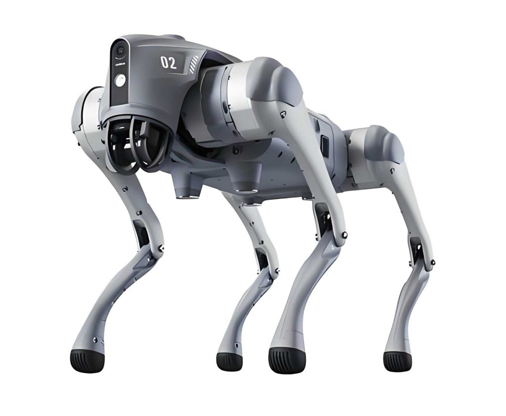
- Perception Layer: Integrated onto a customized pan-tilt unit on the robot dog’s back, it includes four industrial-grade sensors. The visual and infrared modules are coaxially mounted with an optical axis deviation < 0.5°. The acoustic array faces 45° forward, and the millimeter-wave radar is installed horizontally.
- Processing Layer: Centered on an NVIDIA Jetson AGX Orin edge computing unit, it serves as the computational core for real-time data preprocessing, feature extraction, and fusion.
- Communication Layer: Employs a redundant “5G + Industrial Wi-Fi + Optical Fiber” multi-link system for reliable data transmission between the robot dog, the local station control platform, and remote control centers.
Sensor Selection and Specifications
Sensors were chosen to target specific fault types prevalent in new energy stations (e.g., PV panel cracks, wind turbine blade noises, cable overheating). All selected components meet industrial-grade wide-temperature (-40°C to 70°C) and IP67 standards.
| Sensor Type | Model/Specifications | Core Parameters | Primary Inspection Targets |
|---|---|---|---|
| Visual Module | 20MP Global Shutter Camera | Resolution: 5472×3648, Frame Rate: 30 fps, Distortion < 1% | PV panel cracks, missing bolts, meter readings, equipment appearance defects |
| Infrared Thermal Imager | 640×512 px Uncooled FPA | Temp. Range: -20~150°C, NETD < 50 mK, Sampling: 10 Hz | Cable joint overheating, PV panel hot spots, abnormal temperature rise |
| Acoustic Module | 8-channel MEMS Mic Array | Sampling Rate: 48 kHz, SNR > 65 dB, Localization: ±3° | Wind turbine blade abnormal sounds, inverter high-frequency noise |
| Millimeter-wave Radar | 77 GHz FMCW Radar | Range: 0.5~100 m, Range Res.: 0.1 m, Frame Rate: 20 Hz | Obstacle detection in rain/fog, personnel positioning, equipment轮廓 recognition |
Spatio-Temporal Synchronization
Precise fusion requires aligning data in both time and space. A dual “Hardware Trigger + Algorithmic Correction” mechanism is employed.
1. Time Synchronization (based on IEEE 1588 PTP): The edge computing unit’s hardware clock acts as the master. Each sensor is synchronized as a slave, correcting its timestamps:
$$ t_{sync} = t_i + \Delta t_i $$
where \( t_{sync} \) is the synchronized timestamp, \( t_i \) is the raw timestamp from sensor \( i \) (i=1,2,3,4 for vision, IR, acoustic, radar), and \( \Delta t_i \) is a pre-calibrated offset (within ±2 ms).
2. Spatial Calibration (Eye-to-Hand Calibration): Using the robot dog’s body frame (origin at the center of gravity) as the reference, a transformation is established for each sensor:
$$ P_{world} = R_i \cdot P_i + T_i $$
where \( P_{world} \) is the 3D coordinate in the world frame, \( R_i \) is a 3×3 rotation matrix, \( P_i \) is the sensor-local coordinate, and \( T_i \) is a 3×1 translation vector.
Multi-Modal Data Preprocessing
Raw data from each modality undergoes specialized preprocessing to suppress noise and enhance features.
1. Visual Image Processing: Uses Gaussian filtering for noise reduction and a Single-Scale Retinex algorithm for illumination uniformity enhancement.
$$ G(x, y) = \frac{1}{2\pi\delta^2} \exp\left(-\frac{x^2 + y^2}{2\delta^2}\right) $$
$$ L_{enhanced}(x, y) = \log I(x, y) – \log(G(x, y) * I(x, y)) $$
2. Infrared Data Processing: Employs median filtering to remove isolated hot pixels and min-max normalization to standardize temperature values.
$$ T_{norm} = \frac{T – T_{min}}{T_{max} – T_{min}} $$
3. Acoustic Signal Processing: A 256-order NLMS adaptive filter suppresses steady-state noise. The signal is then converted to a Mel-spectrogram via STFT.
$$ Mel(f) = 2595 \log_{10}\left(1 + \frac{f}{700}\right) $$
4. Millimeter-wave Radar Data Processing: A four-stage pipeline (Wavelet-denoising → CA-CFAR clutter suppression → DBSCAN clustering → Feature normalization & Kalman filtering) is used to extract clean target point clouds with associated velocity.
Multi-Modal Fusion Layer Design
A two-tier “Feature-level + Decision-level” fusion architecture is designed to integrate information comprehensively.
Feature-Level Fusion (Attention Mechanism)
Features are first extracted from each modality: 128-dim SIFT features (Vision), 64-dim temperature distribution features (IR), 256-dim Mel-spectral features (Acoustic), 32-dim range-Doppler features (Radar). An attention mechanism assigns weights based on feature entropy \( H(F_i) \), where lower entropy indicates more concentrated/valuable information.
$$ w_i = \frac{1 – H(F_i)}{\sum_{j=1}^{4} (1 – H(F_j))} $$
$$ \text{where } H(F_i) = -\sum_{k=1}^{n} p_{ik} \log p_{ik} $$
The weighted features are then concatenated into a unified 512-dimensional fusion vector:
$$ F_{fusion} = \sum_{i=1}^{4} w_i \cdot F_i $$
Decision-Level Fusion (D-S Evidence Theory)
This layer resolves conflicts between preliminary decisions from different modalities. Each modality provides a Basic Probability Assignment (BPA) \( m_i \) over the hypothesis set \( \Theta = \{\theta_1(\text{Normal}), \theta_2(\text{Minor Fault}), \theta_3(\text{Severe Fault})\} \).
Evidence from two modalities is combined using Dempster’s rule:
$$ m(\theta_j) = \frac{\sum_{A \cap B = \theta_j} m_1(A) \cdot m_2(B)}{1 – \sum_{A \cap B = \emptyset} m_1(A) \cdot m_2(B)} $$
The final equipment state is determined by selecting the hypothesis with the highest combined belief mass \( m(\theta_j) \) after fusing all four modalities.
Decision and Execution Layer Design
Dynamic Path Planning (Improved RRT* Algorithm)
The robot dog’s navigation uses an Improved RRT* algorithm that incorporates a multi-objective cost function based on a multi-modal environment model (static obstacles from radar+vision, dynamic obstacles from radar).
The cost function for evaluating a path is:
$$ \text{Cost} = \alpha \cdot L + \beta \cdot S + \gamma \cdot P $$
where \( L \) is path length, \( S \) is a safety distance penalty (requires \( S \geq 0.5 \) m), and \( P \) represents device priority (e.g., Wind Turbine=3, Inverter=2, PV Panel=1). The weights \( \alpha=0.3, \beta=0.5, \gamma=0.2 \) were optimized experimentally. A post-processing greedy pruning step ensures path smoothness.
Fully Autonomous Inspection Workflow
- Task Initialization: The backend platform sends a task list. The robot dog plans an initial path.
- Real-time Execution: The robot dog navigates, adapts gait to terrain, and collects multi-modal data periodically (e.g., every 30s).
- State Assessment & Fault Feedback: The fusion layer assesses data. If a fault is detected, an audible/visual alarm is triggered, and fault details (image, precise location via SLAM+GNSS, type) are uploaded via 5G.
- Autonomous Return & Charging: Upon low battery (<20%) or task completion, the robot dog autonomously navigates to a charging dock for fast recharging.
Experimental Research and Results Analysis
Experimental Setup
Metrics: Five key metrics were defined: Fault Identification Accuracy, Fault Miss Rate, Fault Misclassification Rate, Inspection Time Consumption, and Obstacle Avoidance Success Rate.
Compared Solutions:
1. Single-Vision Robot Dog: Baseline with only a visual camera.
2. Traditional Manual Inspection: A 3-person team with standard tools.
3. Proposed Multi-Modal Robot Dog: The full system with four sensor modalities.
All robot dog platforms used a Unitree B2 chassis and NVIDIA Jetson AGX Orin compute unit.
Test Scenarios: A 200 MW hybrid wind-PV-storage plant was used, with three challenging areas: PV Array (uneven illumination), Wind Turbine Base (strong EMI >80 dB), and Outdoor Cable Area (rain/fog, visibility ~50m). 50 preset faults were deployed.
Results and Analysis
1. Performance Under Controlled (Static) Conditions:
| Solution | Accuracy (%) | Miss Rate (%) | Misclassification Rate (%) |
|---|---|---|---|
| Single-Vision Robot Dog | 74.0 | 20.0 | 6.0 |
| Traditional Manual Inspection | 82.0 | 12.0 | 6.0 |
| Proposed Multi-Modal Robot Dog | 96.0 | 2.0 | 2.0 |
The multi-modal robot dog’s superior performance stems from cross-validation; e.g., infrared detects hot spots in shadows where vision fails, and acoustics verifies ambiguous cases.
2. Performance in Dynamic Field Scenarios:
| Scenario & Solution | Accuracy (%) | Miss Rate (%) | Inspection Time (min) | Obstacle Avoidance (%) | Avg. Path Dev. (cm) |
|---|---|---|---|---|---|
| PV Array Single-Vision Robot Dog Manual Inspection Multi-Modal Robot Dog |
73.3 86.7 96.7 |
20.0 10.0 3.3 |
58 95 38 |
78.3 – 100 |
12.7 – 4.5 |
| Wind Turbine Base Single-Vision Robot Dog Manual Inspection Multi-Modal Robot Dog |
70.0 83.3 96.7 |
20.0 13.3 3.3 |
65 120 42 |
72.5 – 100 |
18.3 – 4.2 |
| Cable Area (Rain/Fog) Single-Vision Robot Dog Manual Inspection Multi-Modal Robot Dog |
63.3 70.0 93.3 |
26.7 23.3 3.3 |
62 105 40 |
86.7 – 100 |
15.2 – 4.8 |
Key Findings:
- Accuracy & Robustness: The multi-modal robot dog maintained high accuracy (avg. 95.6%) across all harsh scenarios, with minimal performance drop in rain/fog, thanks to radar and infrared. Single-vision and manual methods degraded significantly.
- Efficiency: The robot dog’s average inspection time (40 min) was 2.7 times faster than manual inspection (106.7 min) and 54% faster than the single-vision robot dog, due to efficient path planning and parallel data collection.
- Safety & Precision: The multi-modal robot dog achieved 100% obstacle avoidance using radar, compared to 79.2% for single-vision. Its average path deviation of 4.5 cm met the stringent ±5 cm positioning requirement for inspection points.
3. Long-Term Pilot Application (3 Months):
- The multi-modal robot dog performed daily autonomous inspections over a 2 km² area.
- It identified 47 faults across 1200 equipment inspections, 49% of which were early-stage minor faults.
- By enabling proactive maintenance, it prevented an estimated 1.2 million kWh of generation loss, translating to ~$60,000 in direct economic benefit (at $0.05/kWh).
- The annualized operational cost for the robot dog system was approximately $19,000/station, representing a 62% reduction compared to the ~$50,000/year cost for a traditional 3-person manual team.
Conclusion
This paper presents a comprehensive solution for fully autonomous inspection in new energy power stations by integrating a multi-modal fusion perception system with an agile robot dog platform. The core contributions are threefold:
First, a complete technical architecture was established, featuring a four-modality (Visual, Infrared, Acoustic, Millimeter-wave Radar) sensor suite integrated onto the robot dog. High-precision spatio-temporal synchronization (time < 10 ms, space < 5 cm) and a two-tier fusion strategy (feature-level attention fusion + decision-level D-S evidence theory) were implemented to overcome the limitations of single-modal perception.
Second, extensive experimental validation confirmed the system’s high performance and practicality. In complex field environments (PV arrays under uneven light, wind turbine bases with EMI, cable areas in rain/fog), the multi-modal robot dog achieved an average fault identification accuracy of 95.6%, a 2.7x efficiency gain over manual inspection, and perfect (100%) obstacle avoidance. The pilot application demonstrated significant economic value, preventing substantial generation loss and reducing annual inspection costs by 62%.
Finally, this work provides a viable new path for the intelligent, unmanned operation and maintenance of new energy assets. The system breaks through environmental bottlenecks such as harsh weather and strong interference, enabling truly autonomous, 24/7 inspection that covers all major fault types (appearance, temperature, sound). It aligns perfectly with the industry’s dual-carbon goals of reducing costs and increasing efficiency, offering strong technical support for large-scale deployment.