
The rotary vector reducer stands as a cornerstone of modern precision motion control, particularly in industrial robotics where high torque, compactness, high reduction ratios, and excellent positional accuracy are paramount. Conventional rotary vector reducer designs typically integrate a first-stage involute planetary gear set with a second-stage cycloidal-pin wheel planetary mechanism based on an external cycloidal disc. In this work, we propose and investigate a novel architectural evolution of the rotary vector reducer, where the second-stage transmission is fundamentally re-engineered utilizing the principle of internal-cycloidal planetary gearing. This innovative approach yields a mechanism that retains the core advantages of traditional rotary vector reducer—such as high reduction ratios and compactness—while introducing distinct benefits including an even more favorable axial-to-radial dimension ratio, enhanced potential for a large central hollow shaft, and improved structural stiffness. This article details the complete design methodology, virtual prototype development for multi-body dynamics simulation, and comprehensive modal analysis of this novel internal-cycloid rotary vector reducer, establishing a foundation for its performance evaluation and optimization.
Introduction and Motivation for a Novel Design
The operational principle of the mainstream rotary vector reducer is well-established. It achieves its high single-stage reduction ratio through a two-stage power flow. The input rotation is first decelerated by a standard involute planetary gear train. The output from this first stage drives the eccentric crankshafts of the second stage. These crankshafts, in turn, cause the oscillation of cycloidal discs (in an external cycloid design) which mesh with a stationary ring of pin gears. The oscillating motion of the cycloidal discs is then converted into a reduced rotational output via a planet carrier or an output flange. The robustness and performance of this classic rotary vector reducer design have been extensively studied through virtual prototyping, contact mechanics, and dynamic analysis, focusing on areas such as transmission accuracy, load distribution, torsional stiffness, and the influence of component errors and deformations.
Recent research trends explore not only the refinement of existing rotary vector reducer designs but also fundamental architectural innovations. Scholars have investigated pinless cycloidal drives, novel tooth profiles like trapezoidal shapes, multi-stage cycloidal systems, and even gearless reducers using rolling elements, all aiming to push the boundaries of load capacity, efficiency, noise reduction, and backlash elimination. Inspired by these advancements, our work focuses on a significant topological modification: replacing the external cycloid disc and pin gear ring with an internal-cycloid gear pair. In this novel configuration, the cycloidal profile is on the inner diameter of a rotating gear, which meshes with pin gears mounted on the stationary housing. This inversion of the engagement relationship fundamentally alters the force flow and structural layout. The primary advantages we target with this novel internal-cycloid rotary vector reducer are a more compact axial build, a natural and structurally robust hollow center for cabling or passages, inherent unilateral sealing capability, and potentially improved dynamic characteristics. The following sections will systematically present the theoretical foundation, detailed design, dynamic simulation, and modal analysis of this proposed novel rotary vector reducer.
Theoretical Foundation: Internal-Cycloid Tooth Profile Generation
The internal cycloidal drive is a type of small tooth difference planetary transmission. In our novel rotary vector reducer, the fixed ring gear is a pin gear, while the rotating planet gear (the internal cycloidal disc) has a tooth profile derived from the equidistant curve of a curtate internal epicycloid. The generation principle is geometrically distinct from the external cycloid used in traditional rotary vector reducers.
As illustrated conceptually, consider a base circle with center $$O_a$$ and radius $$R_z$$. A rolling circle with center $$O$$ and radius $$r$$ rolls without slip *inside* this base circle. A tracing point $$M$$ is fixed at a distance $$OM$$ from the center of the rolling circle. The trajectory of point $$M$$ as the rolling circle performs its internal planetary motion is a curtate internal epicycloid. The center points of the fixed pin gears (e.g., $$M_1$$, $$M_2$$, …) are uniformly distributed on a circle of radius $$R$$ (the pin distribution circle), which corresponds precisely to points on this curtate epicycloid. The actual tooth profile of the internal cycloidal disc is the outer equidistant curve of this theoretical epicycloid, offset by the radius of the pin gear, $$r_z$$. The number of pin teeth, $$z_b$$, is typically one less than the number of lobes on the cycloidal disc, $$z_a$$ (i.e., $$z_a – z_b = 1$$).
The derivation of the tooth profile equations is critical for precise manufacturing and analysis of this novel rotary vector reducer. Let $$A = O_aO_b$$ be the eccentricity (the distance between the base circle center and the pin distribution circle center). Let $$K_1 = OM / r$$ be the shortening coefficient of the theoretical internal epicycloid. The parameter $$\psi$$ is the angle through which the center of the rolling circle $$O$$ rotates about the base circle center $$O_a$$.
The parametric equations for the coordinates $$(x_0, y_0)$$ of the *theoretical* internal cycloidal profile are given by:
$$ x_0 = \frac{z_b}{K_1} A \cos \psi + A \cos(z_b \psi) $$
$$ y_0 = \frac{z_b}{K_1} A \sin \psi + A \sin(z_b \psi) $$
To obtain the *actual* tooth profile of the internal cycloidal wheel, we must offset the theoretical curve outward by the pin radius $$r_z$$ along the normal direction. The parametric equations for the final manufacturing profile $$(x, y)$$ are more complex:
$$ x = \cos \psi \left( A\frac{z_b}{K_1} + \frac{r_z}{W_1^{”}} \right) + \cos(z_b \psi) \left( A – \frac{K_1 r_z}{W_1^{”}} \right) $$
$$ y = \sin \psi \left( A\frac{z_b}{K_1} + \frac{r_z}{W_1^{”}} \right) – \sin(z_b \psi) \left( A – \frac{K_1 r_z}{W_1^{”}} \right) $$
where the auxiliary variable $$W_1^{‘}$$ is defined as:
$$ W_1^{‘} = \sqrt{1 + K_1^2 – 2K_1 \cos[(z_b + 1)\psi]} $$
These equations are fundamental for modeling the core transmission component of our novel internal-cycloid rotary vector reducer.
Structural Design of the Novel Internal-Cycloid Rotary Vector Reducer
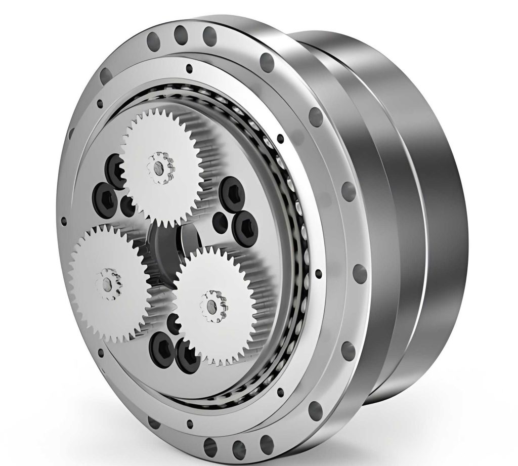
Building upon the internal-cycloid principle, we designed a complete rotary vector reducer assembly. The first stage remains a standard involute planetary gear train to achieve an initial speed reduction and power split. However, the output from the planetary carrier is linked to two eccentric crankshafts, which drive the novel internal cycloidal discs. These discs, with their internally cut cycloidal teeth, mesh with a ring of stationary pin gears housed in the reducer’s fixed casing. The rotation of the internal cycloidal discs, induced by the eccentric motion, is then transmitted to the output flange through a set of rollers or a parallel crank mechanism. This configuration inverts the traditional layout.
The key comparative advantages of this novel design over a conventional external-cycloid rotary vector reducer are summarized in the table below:
| Design Feature | Conventional External-Cycloid RV Reducer | Novel Internal-Cycloid RV Reducer |
|---|---|---|
| Cycloid-Pin Engagement | External meshing (disc outside pins) | Internal meshing (disc inside pins) |
| Axial Length | Relatively larger due to external disc arrangement | Potentially more compact |
| Central Hollow Shaft | Feasible, but size may be constrained by internal components | Easier to implement with a larger diameter, as pins are outward |
| Output Structure Connection | Typically requires specific sealing on output side | Facilitates single-sided sealing; output connection is more straightforward |
| Overall Stiffness | High | Potentially higher due to more compact, integrated housing for pins |
For the purpose of simulation and analysis, a specific set of key technical parameters was defined for our novel rotary vector reducer prototype. These parameters guided the 3D modeling of all critical components, including the sun gear, planetary gears, crankshafts, internal cycloidal discs, pin gears, and the output flange. The assembly was meticulously checked for static and dynamic interferences.
| Parameter | Value |
|---|---|
| Pin Distribution Circle Diameter | 50 mm |
| Pin Diameter ($$r_z$$) | 4 mm |
| Eccentricity ($$A$$) | 1 mm |
| Number of Internal Cycloidal Disc Lobes ($$z_a$$) | 41 |
| Number of Pin Teeth ($$z_b$$) | 40 |
| First-Stage Sun Gear (Input) Teeth | 102 |
| First-Stage Planetary Gear Teeth | 17 |
| First-Stage Ring Gear (Fixed) Teeth | 63 |
| Gear Module (First Stage) | 2 mm |
| Pressure Angle (First Stage) | 20° |
| Motor Input Speed | 1500 rpm |
| Motor Output Pinion Teeth | 34 |
| Calculated Total Reduction Ratio | Approx. 32 |
Multi-Body Dynamics Simulation and Virtual Prototype Analysis
To validate the kinematic and basic dynamic behavior of the novel internal-cycloid rotary vector reducer, a detailed virtual prototype was constructed and simulated using multi-body dynamics software (exemplified by ADAMS). The 3D CAD model was imported, and all necessary kinematic joints and constraints were applied to accurately represent the real mechanism’s motion. The model included two planetary gears, two crankshafts with eccentric sections, two internal cycloidal discs, and 40 pin gears fixed to the housing. The most critical interaction—the contact force between the internal cycloidal disc teeth and the pin gears—was modeled using a robust impact function based on the IMPACT contact algorithm, which accounts for stiffness, damping, and friction.
The simulation was run under defined operational conditions. The input was applied as a rotational velocity to the sun gear. Given a motor speed of 1500 rpm and a 34-tooth motor pinion driving the 102-tooth sun gear, the effective input speed to the rotary vector reducer’s sun gear is:
$$ \omega_{sun} = 1500 \times \frac{34}{102} = 500 \text{ rpm} = 3000 \text{ deg/s} $$
A constant resistive torque of 681 N·m was applied to the output flange to simulate a rated load. The total reduction ratio $$i_{total}$$ can be verified from the first-stage planetary ratio and the second-stage cycloidal ratio. For our design:
$$ i_{total} = \left(1 + \frac{z_{ring}}{z_{sun}}\right) \times \frac{z_b}{1} = \left(1 + \frac{63}{102}\right) \times 40 \approx 32.4 $$
This correlates with the expected output speed:
$$ \omega_{output} \approx \frac{\omega_{sun}}{i_{total}} = \frac{3000}{32.4} \approx 92.6 \text{ deg/s} \quad (\text{or } \approx 15.4 \text{ rpm}) $$
The simulation results confirmed the fundamental kinematic correctness of our novel rotary vector reducer design. The angular velocity curves for the input sun gear and the output flange showed a constant, stable speed ratio corresponding to the design reduction ratio, with the output rotating in the same direction as the input.
The motion of the internal cycloidal disc’s center of mass is particularly illustrative of the second-stage mechanism’s operation. The disc does not rotate purely; its center follows a circular path due to the eccentric crankshaft. The simulation output for the disc’s center of mass velocity components over one full output revolution clearly demonstrates this principle. The X-component of the velocity follows a sinusoidal pattern, while the Y-component follows a cosine pattern, and their combination results in a circular trajectory. The amplitude of this velocity is directly related to the eccentricity $$A$$ and the rotational speed of the crankshaft.
A critical performance metric for any rotary vector reducer is the nature of the contact forces between the cycloidal element and the pins. For our novel internal-cycloid design, we analyzed the contact force on a single representative pin gear during its engagement with one cycloidal disc over a complete cycle. The forces in the X and Y directions exhibited periodic, wave-like patterns. The X-direction force generally followed a sinusoidal trend, and the Y-direction force a cosinusoidal trend, consistent with the rolling engagement of the cycloidal profile. The magnitude and fluctuation of these forces are influenced by the number of teeth in simultaneous contact, manufacturing tolerances, and system dynamics. The observed periodic variation is inherent to cycloidal gearing but must be minimized through optimal profile design and precision manufacturing to ensure smooth operation and long life of the rotary vector reducer.
Finite Element Modal Analysis for Dynamic Characterization
Beyond kinematic simulation, understanding the dynamic vibrational characteristics of the novel rotary vector reducer is essential to avoid resonance and ensure operational stability. We conducted a constrained modal analysis using the Finite Element Method (FEM) on both key components and the fully assembled reducer. The goal was to identify the natural frequencies and corresponding mode shapes of the system.
The modal analysis was performed separately on critical components like the crankshaft and the internal cycloidal disc under fixed boundary conditions simulating their assembly state. Subsequently, a full-assembly modal analysis was conducted with the housing fixed. The results are summarized in the table below, comparing the first 12 natural frequencies of the full assembly with the constrained-mode frequencies of the individual crankshaft and internal cycloidal disc.
| Mode Number | Full Assembly Frequency (Hz) | Crankshaft Constrained Frequency (Hz) | Internal Cycloidal Disc Constrained Frequency (Hz) |
|---|---|---|---|
| 1 | 2,455.0 | 16,648.0 | 649.7 |
| 2 | 2,542.9 | 16,730.0 | 1,126.1 |
| 3 | 2,624.8 | 33,355.0 | 1,924.6 |
| 4 | 2,718.3 | 33,947.0 | 3,116.9 |
| 5 | 2,876.6 | 37,955.0 | 3,178.3 |
| 6 | 2,965.6 | 46,421.0 | 4,107.9 |
| 7 | 2,986.7 | 58,858.0 | 4,634.8 |
| 8 | 3,059.5 | 64,640.0 | 5,273.6 |
| 9 | 3,110.3 | 64,840.0 | 5,608.9 |
| 10 | 3,435.5 | 71,486.0 | 5,965.0 |
| 11 | 3,559.2 | 73,294.0 | 6,577.7 |
| 12 | 3,587.2 | 73,502.0 | 7,284.4 |
The analysis yields several important insights for the novel rotary vector reducer. First, the fundamental natural frequency of the full assembly is relatively high (above 2.4 kHz), indicating good inherent stiffness. Second, the crankshaft’s natural frequencies are significantly higher than the assembly’s modes, meaning it is unlikely to be a source of resonance within the operational range. Third, a potential coupling point is noted: the 4th constrained mode frequency of the internal cycloidal disc (3,116.9 Hz) is very close to the 9th assembly mode frequency (3,110.3 Hz). This suggests that under certain dynamic excitations, there could be a risk of local resonance in the cycloidal disc. This finding is crucial for the detailed design phase, indicating that the geometry or mounting of the internal cycloidal disc may require slight modification (e.g., ribbing, thickness optimization) to detune this frequency and avoid dynamic coupling.
Finally, we verify that the operational excitation frequencies are far removed from these natural frequencies. The primary rotational frequencies are:
$$ f_{sun} = \frac{500 \text{ rpm}}{60} = 8.33 \text{ Hz} $$
$$ f_{crank} = f_{sun} \times \left(1 + \frac{z_{ring}}{z_{sun}}\right) = 8.33 \times \left(1 + \frac{63}{102}\right) \approx 14.5 \text{ Hz} $$
$$ f_{output} = \frac{500 / 32.4}{60} \approx 0.26 \text{ Hz} $$
These very low excitation frequencies confirm that the novel internal-cycloid rotary vector reducer, as designed, will operate safely away from its resonant zones, ensuring stable dynamic performance.
Conclusion
In this work, we have presented a comprehensive study on a novel internal-cycloid rotary vector reducer. The design principle, based on inverting the traditional cycloid-pin engagement to an internal meshing configuration, was detailed through rigorous mathematical formulation of the tooth profile. A complete 3D model was developed, leading to the creation of a virtual prototype for multi-body dynamics simulation. The simulation results successfully validated the fundamental kinematics of the novel reducer, demonstrating correct speed reduction and revealing the characteristic periodic contact forces between the internal cycloidal disc and the pin gears. Furthermore, a finite element modal analysis provided deep insight into the dynamic characteristics of the system, identifying natural frequencies and highlighting a potential point for design optimization concerning the internal cycloidal disc’s vibration mode.
The proposed novel rotary vector reducer architecture offers tangible benefits, including a compact axial form factor, ease of creating a large central hollow shaft, and potentially enhanced system stiffness. The simulation and analysis results establish a strong foundation for the feasibility of this design concept. Future work will focus on detailed parametric optimization of the internal cycloidal profile for improved load distribution and efficiency, advanced nonlinear contact dynamics simulations under varying load conditions, thermal analysis, and ultimately the construction and experimental testing of a physical prototype to correlate with the virtual models. This research contributes a viable new direction in the evolution of high-performance rotary vector reducer technology for demanding applications in robotics and precision machinery.