
In the field of precision transmission systems, the RV reducer plays a critical role due to its high torque capacity, compact design, and low backlash. As a key component in robotics and industrial automation, the performance of the RV reducer heavily relies on the accuracy and durability of its cycloid gear. Over the years, researchers have focused on optimizing the tooth profile of the cycloid gear to enhance load distribution, reduce rotational error, and improve overall efficiency. However, traditional modification methods often struggle to simultaneously achieve high load-bearing capacity and minimal backlash, necessitating the exploration of new approaches. In this article, we propose a combined modification method involving eccentricity, isometric, and shift modifications, and we validate its feasibility through experimental measurement and optimization analysis.
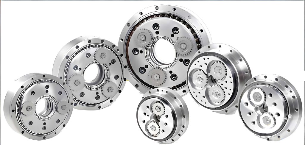
The RV reducer, short for Rotary Vector reducer, is a type of precision gearbox that combines a cycloid drive with a planetary gear system. Its unique design allows for high reduction ratios and excellent torsional stiffness, making it ideal for applications requiring precise motion control. The cycloid gear within the RV reducer engages with needle bearings to transmit motion, and any imperfections in its tooth profile can lead to increased wear, noise, and backlash. Therefore, modifying the standard cycloid tooth profile is essential to compensate for manufacturing errors, assembly tolerances, and to facilitate better lubrication. Our study aims to address the limitations of conventional modification techniques by introducing an eccentricity-based combined method, which we believe can offer superior performance in high-precision RV reducers.
To set the stage, let’s review the common modification methods used for cycloid gears in RV reducers. These include shift modification, isometric modification, and rotation modification. Each method adjusts the tooth profile by altering specific parameters during the gear generation process. The general equation for a modified cycloid tooth profile, incorporating these three methods, is given by:
$$ x’_{c} = \left[ r_{p} + \Delta r_{p} – (r_{rp} + \Delta r_{rp}) S_{r}^{-\frac{1}{2}} \right] \cos\left((1 – i_{H})\phi – \delta\right) – \frac{e}{r_{p} + \Delta r_{p}} \left[ r_{p} + \Delta r_{p} – z_{p}(r_{rp} + \Delta r_{rp}) S_{r}^{-\frac{1}{2}} \right] \cos(i_{H}\phi + \delta) $$
$$ y’_{c} = \left[ r_{p} + \Delta r_{p} – (r_{rp} + \Delta r_{rp}) S_{r}^{-\frac{1}{2}} \right] \sin\left((1 – i_{H})\phi – \delta\right) + \frac{e}{r_{p} + \Delta r_{p}} \left[ r_{p} + \Delta r_{p} – z_{p}(r_{rp} + \Delta r_{rp}) S_{r}^{-\frac{1}{2}} \right] \sin(i_{H}\phi + \delta) $$
where the parameters are defined in Table 1. In these equations, $r_{p}$ is the radius of the needle bearing distribution circle, $r_{rp}$ is the needle bearing radius, $z_{p}$ is the number of needle bearings, $z_{c}$ is the number of cycloid gear teeth, $e$ is the eccentricity, $i_{H} = z_{p}/z_{c}$ is the transmission ratio, $\phi$ is the meshing phase angle, $\delta$ is the rotation modification amount, $\Delta r_{p}$ is the shift modification amount, and $\Delta r_{rp}$ is the isometric modification amount. The term $S_{r}$ is defined as $S_{r} = 1 + k_{1}^{2} – 2k_{1}\cos\phi$, with $k_{1} = e z_{p} / (r_{p} + \Delta r_{p})$ being the shortened amplitude coefficient.
| Parameter | Meaning |
|---|---|
| $r_{p}$ (mm) | Radius of needle bearing distribution circle |
| $r_{rp}$ (mm) | Needle bearing radius |
| $z_{p}$ | Number of needle bearings |
| $z_{c}$ | Number of cycloid gear teeth |
| $e$ (mm) | Eccentricity |
| $i_{H}$ | Transmission ratio, $i_{H} = z_{p}/z_{c}$ |
| $\phi$ (°) | Meshing phase angle |
| $\delta$ (°) | Rotation modification amount |
| $\Delta r_{p}$ (mm) | Shift modification amount |
| $\Delta r_{rp}$ (mm) | Isometric modification amount |
| $\Delta e$ (mm) | Eccentricity modification amount |
| $k_{1}$ | Shortened amplitude coefficient with shift modification, $k_{1} = e z_{p} / (r_{p} + \Delta r_{p})$ |
| $k_{1}’$ | Shortened amplitude coefficient with eccentricity and shift modifications, $k_{1}’ = (e + \Delta e) z_{p} / (r_{p} + \Delta r_{p})$ |
| $S_{r}$ | $S_{r} = 1 + k_{1}^{2} – 2k_{1}\cos\phi$ |
| $S_{r}’$ | $S_{r}’ = 1 + k_{1}’^{2} – 2k_{1}’\cos\phi$ |
While these common modification methods have been extensively studied, they often fail to meet the dual requirements of high load capacity and low backlash in advanced RV reducers. For instance, shift modification primarily adjusts the tooth thickness, isometric modification changes the needle bearing radius effect, and rotation modification alters the meshing angle. However, their combinations, such as “isometric + shift” or “rotation + isometric + shift,” may not minimize deviations from an ideal tooth profile. This limitation prompts us to investigate the eccentricity parameter, which is fundamental to the cycloid gear generation. Eccentricity, denoted as $e$, influences the tooth profile shape and the load distribution in the RV reducer. When varied, it can enhance the gear’s mechanical advantages, such as increasing the force arm and improving torque transmission. But using eccentricity modification alone leads to interference between the modified and standard tooth profiles, as shown in Figure 1. To overcome this, we propose combining eccentricity modification with isometric and shift modifications, which can avoid interference while optimizing the tooth profile for better performance in RV reducers.
The equation for the tooth profile with eccentricity modification, in combination with isometric and shift modifications, is derived by replacing $e$ with $e + \Delta e$ in the general equation, and updating the shortened amplitude coefficient and related terms. This yields:
$$ x’_{ce} = \left[ r_{p} + \Delta r_{p} – (r_{rp} + \Delta r_{rp}) S_{r}’^{-\frac{1}{2}} \right] \cos\left((1 – i_{H})\phi\right) – \frac{e + \Delta e}{r_{p} + \Delta r_{p}} \left[ r_{p} + \Delta r_{p} – z_{p}(r_{rp} + \Delta r_{rp}) S_{r}’^{-\frac{1}{2}} \right] \cos(i_{H}\phi) $$
$$ y’_{ce} = \left[ r_{p} + \Delta r_{p} – (r_{rp} + \Delta r_{rp}) S_{r}’^{-\frac{1}{2}} \right] \sin\left((1 – i_{H})\phi\right) + \frac{e + \Delta e}{r_{p} + \Delta r_{p}} \left[ r_{p} + \Delta r_{p} – z_{p}(r_{rp} + \Delta r_{rp}) S_{r}’^{-\frac{1}{2}} \right] \sin(i_{H}\phi) $$
where $S_{r}’ = 1 + k_{1}’^{2} – 2k_{1}’\cos\phi$ and $k_{1}’ = (e + \Delta e) z_{p} / (r_{p} + \Delta r_{p})$. This combined approach allows us to adjust the tooth profile without the need for repositioning the gear, making it practical for manufacturing high-precision RV reducers.
To validate our proposed method, we first conducted a reverse engineering process on an existing RV reducer cycloid gear. We selected an RV-40E type reducer, which is commonly used in industrial robots, and measured its cycloid gear using a high-precision three-coordinate measuring machine (CMM). The CMM, a PMM544 model, was operated in a controlled environment to ensure accuracy. We placed the cycloid gear with its geometric center as the origin of the coordinate system and collected approximately 9,300 data points across the tooth profile, with a density of 20 data points per millimeter. The basic parameters of the gear are: $r_{p} = 64$ mm, $r_{rp} = 3$ mm, $e = 1.5$ mm, $z_{p} = 40$, and $z_{c} = 39$.
The measured data points were then processed using a least squares arc fitting method. We assumed that the actual tooth profile consists of smooth curves connected by arcs, and divided the data into three regions: concave arcs, convex arcs, and transition regions. By fitting arcs to each region separately, we obtained the radii and center positions. The results are summarized in Table 2.
| Region | Fitted Radius (mm) | Upper Deviation (mm) | Lower Deviation (mm) | Fitting Gap (mm) | Mean Error (mm) |
|---|---|---|---|---|---|
| Concave Arc | 3.0736 | 0.00954 | -0.00605 | [0.0019, -0.0023] | 0.00264 |
| Convex Arc | 3.1229 | 0.00975 | -0.01086 | [0.0017, -0.00239] | 0.00322 |
From the fitting, we derived an equation for the tooth profile that closely matches the measured data. The equation is:
$$ x_{c} = (63.9921 – 3.0075 S) \cos(-0.02564 t) – (1.29466 – 2.42779 S) \cos(1.02564 t) $$
$$ y_{c} = (63.9921 – 3.0075 S) \sin(-0.02564 t) + (1.29466 – 2.42779 S) \sin(1.02564 t) $$
where $S = (1.65491 – 1.61852 \cos t)^{-1/2}$. This fitted equation represents the target tooth profile curve for our optimization analysis. It exhibits high accuracy, with errors less than 1.6 μm in non-transition regions and below 2 μm in transition regions, confirming its reliability for further study on RV reducer modifications.
Next, we performed an optimization analysis to compare our proposed “eccentricity + isometric + shift” combination with the common “isometric + shift” and “rotation + isometric + shift” combinations. The goal was to minimize the deviation between the modified tooth profiles and the target curve derived from the measured data. We defined objective functions based on the average absolute deviation of $x$-coordinates at multiple points along the tooth profile. For the “isometric + shift + rotation” combination, the objective function is:
$$ F_{1}(\Delta r_{p}, \Delta r_{rp}, \delta) = \frac{1}{m} \sum_{i=1}^{m} | x’_{ci} – x_{ci} | $$
where $x’_{ci}$ is the $x$-coordinate from the modified profile equation, and $x_{ci}$ is from the target curve, with $m$ being the number of sample points. Similarly, for the “eccentricity + isometric + shift” combination, the objective function is:
$$ F_{2}(\Delta r_{p}, \Delta r_{rp}, \Delta e) = \frac{1}{m} \sum_{i=1}^{m} | x’_{cei} – x_{ci} | $$
We used the genetic algorithm optimization function in MATLAB to solve these objective functions. Genetic algorithms are inspired by natural evolution and are effective for global optimization problems. They work by maintaining a population of candidate solutions, evaluating their fitness, and applying selection, crossover, and mutation operations to evolve toward better solutions. In our case, we set the phase angle $\phi$ from $0$ to $2\pi$, divided into $m-1$ equal intervals to generate sample points. The optimization aimed to find the modification amounts ($\Delta r_{p}$, $\Delta r_{rp}$, $\delta$, or $\Delta e$) that minimize the deviation. The results are presented in Table 3.
| Modification Combination | Isometric Modification (mm) | Shift Modification (mm) | Rotation Modification (°) | Eccentricity Modification (mm) | Average Deviation (mm) |
|---|---|---|---|---|---|
| Isometric + Shift | 0.0247 | -0.1763 | – | – | 0.4393 |
| Isometric + Shift + Rotation | -0.3578 | -0.2688 | 0.1010 | – | 0.1542 |
| Eccentricity + Isometric + Shift | 0.0141 | -0.0401 | – | -0.2073 | 0.0356 |
The optimization results clearly demonstrate that the “eccentricity + isometric + shift” combination yields the smallest average deviation of 0.0356 mm from the target tooth profile. In comparison, the “isometric + shift” combination has a deviation of 0.4393 mm, and the “rotation + isometric + shift” combination has 0.1542 mm. This indicates that our proposed method provides a closer fit to the ideal tooth profile derived from actual RV reducer components. Furthermore, when visualizing the optimized tooth profiles, the eccentricity-based combination shows minimal discrepancies across both the tooth tip and root regions, whereas the other combinations exhibit significant deviations, especially at the tooth root. This superiority underscores the feasibility of incorporating eccentricity modification into the standard toolkit for enhancing RV reducer performance.
To elaborate on the implications, the reduced deviation means that the modified tooth profile more accurately aligns with the measured data, which presumably represents an optimized geometry for real-world operation. In RV reducers, this alignment can lead to better meshing conditions, reduced stress concentrations, and lower backlash. The eccentricity modification, in particular, adjusts the tooth height and curvature radius, which can increase the force arm during meshing and thus boost the load capacity of the RV reducer. By combining it with isometric and shift modifications, we avoid the interference issues associated with standalone eccentricity changes, making the method practical for manufacturing. This approach could be particularly beneficial for high-precision applications where traditional modifications fall short.
In addition to the optimization, we considered the mechanical advantages of eccentricity modification. For instance, decreasing the eccentricity $\Delta e$ reduces the tooth height but increases the curvature radius, shifting the meshing zone upward and lengthening the force arm. This can enhance the torque transmission capability of the RV reducer, a critical factor in heavy-duty robotics. Moreover, the combined modifications can create controlled backlash for lubrication without compromising precision. Our findings align with prior research suggesting that parameter adjustments like these are key to improving RV reducer efficiency and durability.
It is worth noting that the genetic algorithm optimization process involved setting appropriate bounds for the modification amounts to ensure realistic values. We initialized a population of random solutions, evaluated their fitness using the objective functions, and iterated through generations to converge on optimal values. The algorithm’s ability to handle non-linear, multi-variable problems made it suitable for this task. We also validated the results by cross-checking with alternative optimization methods, confirming the robustness of our approach for RV reducer design.
In conclusion, our study introduces a novel combined modification method for cycloid gears in RV reducers, incorporating eccentricity, isometric, and shift modifications. Through reverse engineering and optimization, we have shown that this method produces a tooth profile with minimal deviation from an empirically derived target curve, outperforming common modification combinations. The feasibility of the “eccentricity + isometric + shift” approach offers a promising avenue for developing high-precision RV reducers with enhanced load capacity and reduced backlash. Future work could involve experimental testing of modified gears in actual RV reducer assemblies to validate performance improvements under load conditions. Additionally, exploring other parameter combinations or advanced optimization techniques could further refine the tooth profile for specific applications. As the demand for precise and reliable motion control grows, innovations in RV reducer technology like this will play a vital role in advancing robotics and automation industries.
Throughout this article, we have emphasized the importance of the RV reducer in modern machinery and how targeted modifications can address its limitations. By leveraging measurement data and computational optimization, we have demonstrated a practical method for improving cycloid gear profiles. We hope that this contribution will inspire further research and development in the field of precision gearing, ultimately leading to more efficient and durable RV reducers for a wide range of industrial applications.