
In the context of deep space exploration, the lunar environment presents significant challenges due to its complex and rugged terrain. We propose a novel quadruped robot dog equipped with a deformable trunk based on the Bricard mechanism, designed to adapt to unstructured lunar surfaces. This robot dog integrates a dual-symmetric Bricard mechanism with wheel-arm foot-end modules, enabling versatile locomotion through trunk deformation. The deformable trunk allows the quadruped robot to switch between multiple configurations, such as hexagonal, quadrilateral, and transitional morphologies, facilitating both universal and environment-adaptive gaits. Our work focuses on the kinematic and dynamic analysis of this quadruped robot, including mobility, obstacle negotiation, and gait planning, supported by extensive simulations. This approach aims to enhance the performance of quadruped robots in extreme lunar conditions, providing a robust solution for future missions.
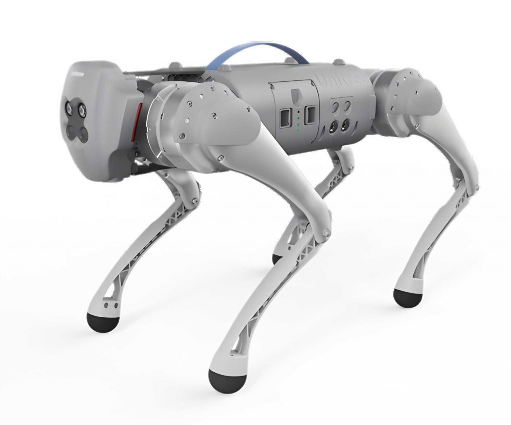
The overall design of the quadruped robot dog incorporates a modular architecture, consisting of a deformable trunk and four wheel-arm foot-end modules. The trunk is based on a dual-symmetric Bricard mechanism, which is a single-degree-of-freedom spatial overconstrained 6R linkage. This mechanism enables the robot dog to achieve compact folding and expanded supporting states, adapting to varying lunar terrains. The wheel-arm foot-end modules combine wheeled and legged locomotion, allowing the quadruped robot to maintain stability and reduce sinking in loose lunar soil. Each module features an irregular contact foot that ensures continuous line contact with the ground, minimizing adhesion risks and enhancing traction. The robot dog has a total of 30 revolute joints and 5 degrees of freedom, controlled by 5 actuators, enabling coordinated movement and deformation.
We analyze the degree of freedom of the deformable trunk using the modified G-K formula. The dual-symmetric Bricard mechanism has a common constraint number λ = 1, mechanism order d = 5, number of links n = 6, number of joints g = 6, and joint freedoms f_i = 1 for i = 1 to 6. With no redundant constraints (v = 0), the degree of freedom F is calculated as:
$$ F = d(n-g-1) + \sum_{i=1}^{g} f_i + v = 5(6-6-1) + 6 + 0 = 1 $$
This confirms that the trunk has one degree of freedom, allowing deterministic motion with a single actuator. The D-H parameters for the Bricard mechanism are defined as follows, with i ranging from 1 to 6 (cyclic indices):
| Parameter | Value |
|---|---|
| a_{12}, a_{34}, a_{45}, a_{61} | a |
| a_{23}, a_{56} | 0 |
| α_{12}, α_{45} | π/2 |
| α_{23}, α_{34}, α_{56}, α_{61} | -π/2 |
| R_1, R_4 | 0 |
| R_2, R_5 | -r |
| R_3, R_6 | r |
where a = 470 mm and r = (40√2 + 3)/47 * a. The joint angle θ_2 at the F_5 joint serves as the input, with a range of [-40°, 220°] to avoid bifurcation points. The bifurcation conditions are given by:
$$ \theta_3 = \theta_2 + \pi, \quad \theta_4 = \theta_1, \quad \tan\left(\frac{\theta_1}{2}\right) = \frac{2\tan\left(\frac{\theta_2}{2}\right)\left(1 – \tan^2\left(\frac{\theta_2}{2}\right)\right)}{\tan^4\left(\frac{\theta_2}{2}\right) – 1} $$
for dual-symmetric bifurcation, and:
$$ \tan\left(\frac{\theta_3}{2}\right) = \frac{\tan\left(\frac{\theta_2}{2}\right) + 3}{3\tan\left(\frac{\theta_2}{2}\right) + 1}, \quad \theta_4 \neq \theta_1 $$
for single-symmetric bifurcation. The bifurcation points are at θ_2 = -43.39° and θ_2 = 223.39°.
For morphology planning, the quadruped robot dog exhibits three main configurations based on θ_2: quadrilateral morphology at θ_2 = 0° or 180°, hexagonal morphology at θ_2 = 90°, and transitional morphology in the intervals [-40°, 0°), (0°, 90°), (90°, 180°), and (180°, 220°]. In quadrilateral morphology, the robot dog has a minimal width, suitable for narrow spaces, with wheel-arm modules at 45° to the ground. In hexagonal morphology, the robot dog has a minimal height, lowering the center of mass for stable motion. Transitional morphology allows continuous shape changes, enabling the quadruped robot to adapt to extreme obstacles by shifting support from four to three feet.
The dimensional changes of the quadruped robot during deformation are analyzed in the coordinate system at point P (x_0, y_0, z_0). The size in the X, Y, and Z directions varies with θ_2. For θ_2 in [-40°, 90°], the X-direction size X_size is given by:
$$ X_{\text{size}} = \sqrt{|x_{xs}|^2 + |y_{xs}|^2 + |z_{xs}|^2} $$
where:
$$ x_{xs} = k \cos \theta_2 + k \cos \theta_3 + x_0 \cos \theta_2 + z_0 \sin \theta_2 + z_0 \sin \theta_3 – x_0 \cos \theta_3 \cos \theta_4 – y_0 \cos \theta_3 \sin \theta_4 $$
$$ y_{xs} = c_3 + y_0 – k \sin \theta_3 + z_0 \cos \theta_3 + x_0 \cos \theta_4 \sin \theta_3 + y_0 \sin \theta_3 \sin \theta_4 $$
$$ z_{xs} = c_3 + k \sin \theta_2 + y_0 \cos \theta_4 – z_0 \cos \theta_2 + x_0 \sin \theta_2 – x_0 \sin \theta_4 $$
The Y-direction size Y_size is:
$$ Y_{\text{size}} = \frac{1}{2} \sqrt{|x_{ys}|^2 + |y_{ys}|^2 + |z_{ys}|^2} $$
where:
$$ x_{ys} = c_1 – 2k \cos \theta_2 + 2x_0 \cos \theta_3 + 2y_0 \sin \theta_2 + 2y_0 \sin \theta_3 – 2k \cos \theta_1 \sin \theta_2 – 2x_0 \cos \theta_1 \sin \theta_2 + 2z_0 \cos \theta_2 \sin \theta_1 $$
$$ y_{ys} = 2c_3 + 2z_0 + c_1 + 2k \sin \theta_2 + 2y_0 \cos \theta_2 + 2k \cos \theta_1 \sin \theta_2 + 2x_0 \cos \theta_1 \sin \theta_2 – 2z_0 \sin \theta_1 \sin \theta_2 $$
$$ z_{ys} = 2c_3 + 2k \sin \theta_1 – 2y_0 \cos \theta_3 + 2z_0 \cos \theta_1 + 2x_0 \sin \theta_1 + 2x_0 \sin \theta_3 $$
The Z-direction size Z_size is:
$$ Z_{\text{size}} = z_{\text{max}} – z_{\text{bottom}} $$
where z_max = max(z_top, z_1), z_top = z_1 – (k_1 + j_1) u_z + 0.5 j_2 w_z, z_bottom = z_1 – (k_1 + j_1) u_z – 0.5 j_2 w_z, z_1 = c_3 + y_0, u_z = k \sin \theta_1 – y_0 + z_0 \cos \theta_1 + x_0 \sin \theta_1, w_z = u_x \cos \theta_2 + u_y \sin \theta_2, u_x = k \cos \theta_1 \cos \theta_2 – y_0 \sin \theta_2 – z_0 \sin \theta_2 – x_0 \cos \theta_2 + x_0 \cos \theta_1 \cos \theta_2 – z_0 \cos \theta_2 \sin \theta_1, and u_y = y_0 \cos \theta_2 + z_0 \cos \theta_2 – x_0 \sin \theta_2 + k \cos \theta_1 \sin \theta_2 + x_0 \cos \theta_1 \sin \theta_2 – z_0 \sin \theta_1 \sin \theta_2.
The mobility of the quadruped robot dog is analyzed for locomotion on lunar soil. The driving force is primarily provided by sliding friction. The ground reaction forces on the four wheel-arm modules are denoted as f_AL, f_AR, f_BL, and f_BR, each calculated as:
$$ f_{AL} = f_{AR} = f_{BL} = f_{BR} = \frac{\mu_s G}{4} $$
where μ_s is the static friction coefficient and G is the gravitational force. The angles σ_L and σ_R between the ground forces and the movement direction vary with the angular displacements β_L and β_R of the left and right drive motors:
$$ \sigma_i = \arctan\left( \frac{\sqrt{2} \cos \beta_i w}{q + v} \right) $$
for i = L or R, where w = 4H cos β_i + 3L sin β_i, q = 4H, and v = L sin 2β_i.
For obstacle negotiation, the quadruped robot dog can climb slopes, cross trenches, and surmount vertical walls. In slope climbing, the robot dog maintains stability with the front wheel-arm modules contacting the slope. The force F_4 from the slope on the contact point is derived from moment equilibrium about O_1:
$$ \frac{G L \cos \beta}{2} + F_4 \sin \theta (H – p \sin \theta) + G_4 L \cos \beta – F_4 \cos \theta (L \cos \beta + p \cos \theta) = 0 $$
Solving for F_4:
$$ F_4 = \frac{(G + G_4) L \cos \beta}{2(L \cos \beta \cos \theta – H \sin \theta + p)} $$
The motor torque T_4 for the front module is:
$$ T_4 = F_4 \cos \theta p \cos \theta – \frac{G r_0 \cos \theta_0}{4} – F_4 \sin \theta (L \sin \beta + H – p \sin \theta) $$
The maximum climbable slope angle θ is given by θ = arctan(μ_Ls). For a friction coefficient of 0.5, θ ≈ 26°.
For trench crossing, the maximum width the robot dog can cross is equal to the length j_2 of the irregular contact foot, as the foot endpoints contact the trench edges. For vertical wall surmounting, the robot dog lifts its front modules. The forces are analyzed using equilibrium equations. The support force F_ND from the wall is:
$$ F_{ND} = \frac{G (l_1 + l_3) r_s}{x r_s – y h} $$
where x = l_1 + l_2 + l_3 + l_4 + r_s cos α, y = l_1 + l_2 + l_3 + l_4, z = (l_2 + l_4 + r_s cos α) r_s G – G h (l_2 + l_4), and α = arcsin((r_s – h)/r_s). The no-slip condition for the rear modules is F_SB ≤ μ F_NB.
We conduct dynamic simulation experiments to validate the performance of the quadruped robot dog. The virtual prototype dimensions are as follows:
| Design Variable (mm) | Value | Design Variable (mm) | Value |
|---|---|---|---|
| j_1 | 215 | k | 470 |
| j_2 | 180 | k_1 | 85 |
| c_1 | 420 | k_2 | 185 |
| c_2 | 40 | k_3 | 175 |
| c_3 | 300 | k_4 | 95 |
The simulation environment parameters abstract lunar terrains:
| Simulation Environment | Horizontal Plane | Slope | Trench | Vertical Wall |
|---|---|---|---|---|
| Static Friction Coefficient | 0.5 | 0.9 | 0.9 | 0.8 |
| Dynamic Friction Coefficient | 0.3 | 0.5 | 0.6 | 0.6 |
| Stiffness (N/m) | 10,000 | 15,000 | 14,000 | 20,000 |
| Damping (N·s/m) | 10 | 18 | 14 | 16 |
| Force Exponent | 2.2 | 2.8 | 2.7 | 2.9 |
| Penetration Depth (m) | 0.1 | 0.05 | 0.07 | 0.05 |
Universal gaits include fixed-direction movement and steering. For fixed-direction movement, adjacent motors M_i and M_{i+1} (i=1,2,3) are driven in-phase within groups and out-of-phase between groups. The robot dog achieves omnidirectional motion with periodic trajectory variations due to the elliptical profile of the contact feet. The steering gait involves coordinated driving of all four motors to deviate from straight-line motion. The relationship between gait and motor phase difference for different trunk morphologies is summarized below:
| Trunk Morphology | Phase Configuration | Gait Type | Phase Difference Range (°) |
|---|---|---|---|
| Hexagonal | State 1 | Large-radius steering | 355 |
| State 2 | Fixed-direction forward | 36 | |
| State 3 | Small-radius steering | 81 | |
| Quadrilateral | State 1 | Large-radius steering | 320 |
| State 2 | Fixed-direction forward | 20 | |
| State 3 | Small-radius steering | 158 |
Environment-adaptive gaits include slope climbing, trench crossing, and vertical wall surmounting. For slope climbing, the robot dog ascends 20° slopes without slippage in all trunk morphologies. The motor torques are adjusted based on the trunk configuration. For trench crossing, the quadruped robot achieves maximum widths of 180 mm in quadrilateral and hexagonal morphologies and 220 mm in transitional morphology, a 22% improvement. For vertical wall surmounting, the robot dog surmounts heights of 100 mm, 120 mm, and 144 mm in quadrilateral, hexagonal, and transitional morphologies, respectively, with a height-to-robot ratio of up to 80%.
The gait-terrain adaptation is summarized as follows:
| Lunar Terrain | Morphology | Applicable Gaits | Specific Gaits |
|---|---|---|---|
| Basic Environment | Quadrilateral, Hexagonal | Universal Gaits | Straight-line, Steering |
| Low-height Space | Hexagonal | Universal + Adaptive Gaits | All Gaits |
| Narrow Space | Quadrilateral | Universal + Adaptive Gaits | All Gaits |
| Extreme Obstacles | Transitional | Adaptive Gaits | Wall Surmounting, Trench Crossing, Slope Climbing |
In conclusion, we have developed a quadruped robot dog with a deformable trunk based on the Bricard mechanism, capable of adapting to lunar unstructured terrains. The trunk’s single degree of freedom enables efficient morphology switching, enhancing mobility and obstacle negotiation. Simulations confirm that this robot dog performs well in various scenarios, including omnidirectional movement, slope climbing, trench crossing, and vertical wall surmounting. The deformable trunk significantly improves performance in extreme environments, offering a viable solution for deep space exploration. Future work will focus on hardware implementation and real-world testing of this advanced quadruped robot.