
Abstract In the realm of robot technology, ensuring the precision of robotic end-effector positioning is critical for advanced manufacturing and industrial applications. This study delves into the analysis of calibration error propagation in the kinematic chain of a six-degree-of-freedom (six-DOF) robotic manipulator’s end-effector pose. By establishing a kinematic parameter model using the Modified Denavit-Hartenberg (MDH) model, we systematically analyze the spatial geometric relationships of end-effector pose transformations and identify key sources of calibration errors. A calibration error propagation model is constructed to quantify the impact of geometric parameter errors on end-effector positioning accuracy. Experimental validation using a six-DOF robot calibration system demonstrates that primary error sources include link length errors, joint offset errors, joint twist angle errors, and zero-position errors. The combined calibration error and relative uncertainties in the x, y, and z directions are quantified, providing essential technical references for precise positioning control in robot technology.
Keywords: robot technology; six-DOF robot; end-effector positioning; calibration; error propagation analysis; MDH model
1. Introduction
The advancement of robot technology has revolutionized industrial manufacturing, particularly in applications requiring high-precision positioning, such as assembly, machining, and transportation of large components. However, factors like transmission clearances, assembly errors, and environmental influences often lead to positioning errors in robotic manipulators, limiting their operational accuracy. Calibration, as a cost-effective method, plays a pivotal role in enhancing the absolute positioning accuracy of robots, making it a focal point in robot technology research.
Geometric parameter errors are among the most significant contributors to robotic positioning inaccuracies, accounting for approximately 90% of total errors. Common calibration models in robot technology, such as the robot-laser tracker model and robot-camera calibration model, have been widely used. The robot-camera model offers low cost but relatively low precision, while the laser tracker model provides higher measurement accuracy, making it suitable for precision applications. Despite their utility, existing methods often lack systematic analysis of error propagation chains, necessitating a more comprehensive approach to understand how individual errors accumulate and affect end-effector pose.
This study aims to address the nonlinear impact of calibration errors on end-effector positioning accuracy by systematically analyzing the error sources and propagation mechanisms in six-DOF robots. Specifically, we develop a kinematic model using the MDH framework, identify key error sources, construct an error propagation model, and validate our findings through experimental testing. The results contribute to improving the precision of robot technology by providing a detailed understanding of error mechanisms and their quantitative effects.
2. Kinematic Modeling of Six-DOF Robots
2.1 MDH Model for Forward Kinematics
In robot technology, the MDH model is a fundamental tool for describing the kinematic behavior of serial manipulators. We employ the MDH model to establish the forward kinematic model of the six-DOF robot, which defines the transformation between consecutive coordinate systems. The homogeneous transformation matrix \(_{i-1}^{i}T\) from frame \(\{i-1\}\) to frame \(\{i\}\) is given by:
\(_{i-1}^{i}T = \text{rot}(x_{i-1}, \alpha_{i-1}) \cdot \text{tran}(a_{i-1}, 0, 0) \cdot \text{rot}(z_i, \theta_i) \cdot \text{tran}(0, 0, d_i)\)
where:
- \(\text{rot}(x, \alpha)\) denotes a rotation about the x-axis by angle \(\alpha\),
- \(\text{tran}(a, 0, 0)\) denotes a translation along the x-axis by distance a,
- \(\theta_i\) is the joint angle about the \(z_i\)-axis,
- \(d_i\) is the offset along the \(z_i\)-axis between frames \(\{i-1\}\) and \(\{i\}\).
The overall transformation from the base frame \(\{0\}\) to the end-effector frame \(\{6\}\) is the product of individual transformations:
\(_{0}^{6}T = \prod_{i=1}^{6} {_{i-1}^{i}T} = \begin{bmatrix} n_x & o_x & a_x & p_x \\ n_y & o_y & a_y & p_y \\ n_z & o_z & a_z & p_z \\ 0 & 0 & 0 & 1 \end{bmatrix}\)
Here, \([n_x, n_y, n_z]^T\), \([o_x, o_y, o_z]^T\), and \([a_x, a_y, a_z]^T\) form the rotation matrix, while \([p_x, p_y, p_z]^T\) represents the position vector of the end-effector in the base frame.
2.2 Zero Position Structure and Coordinate Systems
The zero position structure of the robot, where all joint angles are set to their nominal zero values, serves as the reference configuration for kinematic modeling. In this state, the relationship between the base frame \(\{B\}\) and the flange frame \(\{F\}\) is defined by the zero-position transformation matrix. Accurate modeling of this configuration is essential for subsequent error analysis in robot technology, as any deviation from the nominal zero position directly influences the cumulative error in end-effector pose.
3. Calibration Error Sources and Propagation Model
3.1 Identification of Error Sources
In robot technology, calibration errors arise from multiple interconnected factors. Through systematic analysis, we categorize the primary error sources into five main types:
- Link Length Errors (\(\Delta a_i\)): Deviations in the actual length of robot links from their designed values, caused by manufacturing tolerances, material expansion, or assembly errors. These errors directly affect the spatial reach and positioning accuracy of the manipulator.
- Joint Offset Errors (\(\Delta d_i\)): Misalignments between the actual and nominal axes of rotational or prismatic joints, leading to unexpected translations or rotations in the kinematic chain.
- Zero Position Errors (\(\Delta \theta_{zero}\)): Deviations of joint angles from their nominal zero positions due to sensor drift, assembly inaccuracies, or calibration imperfections. These errors act as initial biases in the kinematic model.
- Joint Twist Angle Errors (\(\Delta \alpha_i\)): Discrepancies between the nominal and actual twist angles (angles between consecutive joint axes) in the MDH model, arising from manufacturing or installation errors.
- Model Errors: Inaccuracies in the kinematic model itself, such as oversimplifications of joint dynamics or neglect of flexible deformations in robot components.
Table 1 summarizes these error sources and their impact mechanisms:
Table 1. Primary Calibration Error Sources in Six-DOF Robots
| Error Source | Symbol | Mechanism of Impact |
|---|---|---|
| Link Length Error | \(\Delta a_i\) | Alters translational component between joint frames |
| Joint Offset Error | \(\Delta d_i\) | Introduces unmodeled translations along joint axes |
| Zero Position Error | \(\Delta \theta_{zero}\) | Shifts initial joint angle references |
| Joint Twist Error | \(\Delta \alpha_i\) | Modifies rotational offsets between consecutive links |
| Model Error | – | Inaccuracies in kinematic assumptions (e.g., rigidity) |
3.2 Error Propagation Model Development
To quantify how individual errors propagate through the kinematic chain, we derive a differential error model based on the MDH framework. Let \(\Delta \mathbf{x}\) represent the vector of small parameter errors:
\(\Delta \mathbf{x} = [\Delta \alpha_0, \dots, \Delta \alpha_5, \Delta a_0, \dots, \Delta a_5, \Delta d_1, \dots, \Delta d_6, \Delta \theta_1, \dots, \Delta \theta_6, \Delta \beta_2, \Delta \beta_3]^T\)
where \(\Delta \beta_i\) denote additional rotational errors about the y-axis. The differential transformation matrix \(\Delta_{i-1}^{i}T\) due to these errors is approximated by the Jacobian of the forward kinematic model:
\(\Delta_{i-1}^{i}T = \frac{\partial _{i-1}^{i}T}{\partial \mathbf{x}} \Delta \mathbf{x} = \delta_{i-1}^{i}T \cdot _{i-1}^{i}T\)
Here, \(\delta_{i-1}^{i}T\) is the differential operator matrix, which can be expressed in terms of rotational and translational components. For small angles, the rotational part of \(\delta_{i-1}^{i}T\) can be approximated as a skew-symmetric matrix:
\(\delta_{i-1}^{i}T_{\text{rot}} = \begin{bmatrix} 0 & -\delta z_i & \delta y_i \\ \delta z_i & 0 & -\delta x_i \\ -\delta y_i & \delta x_i & 0 \end{bmatrix}\)
where \(\delta x_i, \delta y_i, \delta z_i\) are small rotational errors about the x, y, and z axes of frame \(\{i-1\}\). The translational component \(\vec{d_i}\) captures the effect of link length and offset errors:
\(\vec{d_i} = \begin{bmatrix} d x_i \\ d y_i \\ d z_i \end{bmatrix} = \Delta a_{i-1} \mathbf{e}_x + \Delta d_i \cdot \begin{bmatrix} 0 \\ -\sin \alpha_{i-1} \\ \cos \alpha_{i-1} \end{bmatrix} + \dots \text{(higher-order terms)}\)
Combining these effects, the total end-effector pose error \(\Delta \mathbf{P}\) is the cumulative result of errors from all joints, expressed through the Jacobian matrix J:
\(\Delta \mathbf{P} = J \Delta \mathbf{x}\)
where J is a 6xN matrix (N=26 for six-DOF robots) that maps each geometric parameter error to the corresponding end-effector position and orientation error.
4. Experimental Validation in Robot Technology
4.1 Experimental Setup
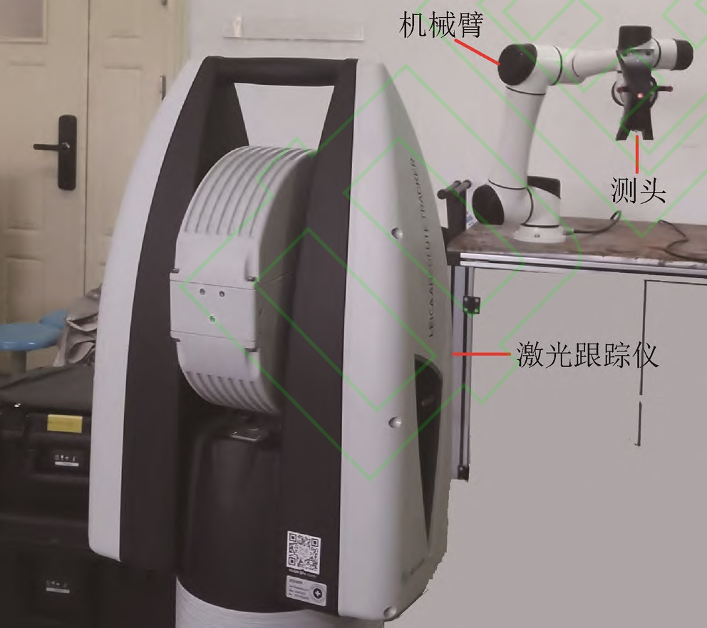
To validate our error propagation model, we conduct experiments using an AR5 six-DOF robot and an AT960 laser tracker, a key tool in precision robot calibration within the field of robot technology. The experimental setup involves:
- Coordinate Pre-Alignment: Aligning the laser tracker coordinate system, robot base frame, and end-effector frame to ensure consistent data acquisition.
- Data Collection: Measuring the end-effector pose at 50 different robot configurations, covering a wide range of the workspace to capture diverse error scenarios.
- Data Processing: Transforming measured data into the robot base frame and comparing it with nominal values to compute pose errors.
Figure 1 illustrates the measurement system, highlighting the laser tracker, robot, and coordinate alignment process.
4.2 Calibration Results and Error Analysis
Using the Levenberg-Marquardt (LM) algorithm, a robust optimization technique in robot technology, we estimate the geometric parameter errors. Table 2 presents the calibrated DH parameters, showing that zero position errors are within ±2 arcseconds, while other parameters exhibit measurable deviations (e.g., \(\Delta d_1 = -0.343\) mm, \(\Delta \alpha_0 = -120.240\) arcseconds).
Table 2. Calibrated DH Parameters Using LM Algorithm
| Joint i | \(\Delta \theta_i\) (arcsec) | \(\Delta d_i\) (mm) | \(\Delta a_i\) (mm) | \(\Delta \alpha_{i-1}\) (arcsec) | \(\beta_i\) (arcsec) |
|---|---|---|---|---|---|
| 1 | -1.514 | -0.343 | -0.014 | -120.240 | – |
| 2 | -0.155 | -0.343 | +0.004 | -174.960 | – |
| 3 | … | … | … | … | … |
| (Full table includes all 6 joints) |
To assess the impact of these errors, we use Monte Carlo simulation to generate 10,000 sets of parameter errors within their uncertainty bounds. Figure 2 shows the resulting end-effector position distributions in the x, y, and z directions. The x-axis distribution is relatively narrow (mean: 748.714 mm, standard deviation: 0.28 mm), while the z-axis exhibits higher variability (standard deviation: 0.61 mm), indicating that certain error sources have more pronounced effects in specific directions.
4.3 Uncertainty Evaluation
Using the Monte Carlo results, we evaluate the uncertainty in end-effector positioning. Table 3 summarizes the standard uncertainty, expanded uncertainty (with coverage factor \(k=2.485\)), and relative uncertainty for each axis. The relative uncertainties in the x, y, and z directions are 0.09%, 0.37%, and 0.46%, respectively, demonstrating that the proposed model effectively quantifies error propagation in robot technology.
Table 3. Uncertainty Evaluation of End-Effector Position
| Axis | Mean Position (mm) | Uncertainty Interval (mm) | Standard Uncertainty (mm) | Expanded Uncertainty (mm) | Relative Uncertainty (%) |
|---|---|---|---|---|---|
| x | 748.714 | (747.725, 749.685) | 0.28 | 0.67 | 0.09 |
| y | 325.056 | (323.494, 327.101) | 0.49 | 1.21 | 0.37 |
| z | 329.829 | (328.625, 331.035) | 0.61 | 1.50 | 0.46 |
5. Discussion
The results highlight the critical role of geometric parameter errors in robot technology and their nonlinear impact on end-effector pose. Link length errors and joint twist angles exhibit significant influence in the x and z directions, respectively, while zero position errors contribute to cumulative biases across all axes. The LM algorithm proves effective for parameter estimation, but its performance depends on the quality and quantity of measurement data—using at least 26 data points (equal to the number of parameters) is essential for unique solutions, as shown in Figure 3.
Comparing our findings with existing methods in robot technology, the proposed error propagation model offers a more systematic approach to error analysis than traditional least-squares methods, which often overlook higher-order error interactions. The Monte Carlo simulation provides a robust framework for uncertainty quantification, enabling engineers to prioritize error sources for mitigation (e.g., focusing on link length calibration for x-axis precision).
6. Conclusion
In this study, we have presented a comprehensive analysis of calibration error propagation in six-DOF robot end-effector pose, a critical aspect of robot technology. By integrating the MDH model, error source identification, and experimental validation, we have demonstrated that link length errors, joint offsets, and twist angles are primary contributors to positioning inaccuracies. The developed error propagation model and uncertainty evaluation framework provide a foundation for improving calibration strategies in robot technology, enabling more precise path planning and trajectory control.
Future work in robot technology may extend this analysis to non-geometric errors (e.g., thermal effects, gear backlash) and explore real-time error compensation techniques, further enhancing the reliability and precision of robotic systems in industrial applications.