
In the field of precision robotics and heavy-duty industrial automation, the rotary vector reducer stands as a critical component due to its high transmission efficiency, compact size, and ability to handle substantial torque loads. As an engineer focused on mechanical transmission systems, I have extensively studied the dynamic behavior and design optimization of rotary vector reducers. This article presents a comprehensive analysis of the transmission forces within a rotary vector reducer, utilizing the osculating value method to evaluate the influence of various geometric and material parameters. The rotary vector reducer, often abbreviated as RV reducer, incorporates a two-stage reduction mechanism: a primary stage with involute spur gears and a secondary stage with cycloidal pin gear transmission. This design enables high reduction ratios and smooth operation, but its complex geometry and manufacturing tolerances necessitate detailed force analysis to ensure reliability and performance. Throughout this discussion, I will emphasize the role of the rotary vector reducer in robotic applications and explore methodologies to enhance its design through parametric studies.
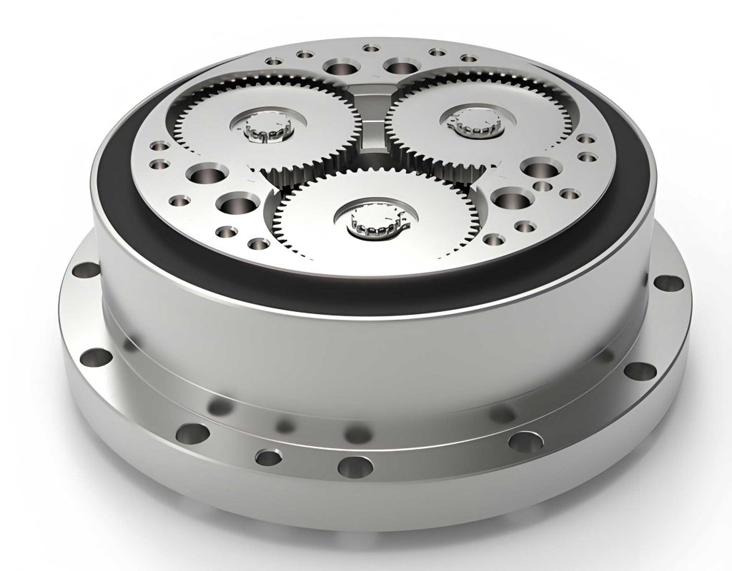
The structural configuration of a typical rotary vector reducer, such as the RV-40E model, involves multiple components including input shafts, planetary gears, crank shafts, cycloidal gears, and pin gears. A simplified representation aids in understanding the kinematic and force relationships. The rotary vector reducer employs two cycloidal gears arranged 180 degrees apart to balance eccentric inertial forces, along with dual crank shafts to distribute loads evenly. This arrangement is pivotal for minimizing vibration and wear in high-precision systems like industrial robots. In my analysis, I begin by deriving the reduction ratio using a relative motion approach, which provides an intuitive alternative to the conventional inversion method. This foundation is essential for subsequent force calculations, as the transmission characteristics directly impact the stress distribution within the rotary vector reducer.
To calculate the reduction ratio of a rotary vector reducer, I consider the geometric relationships and gear meshing principles. Let $\omega_1$ be the angular velocity of the input shaft, and $\omega_5$ be the angular velocity of the output shaft. The cycloidal gear is connected to the output shaft via a “W mechanism,” ensuring that the absolute angular velocity of the cycloidal gear $\omega_3$ equals $\omega_5$. Using velocity analysis at contact points, the reduction ratio $i$ is derived as follows:
$$ i = \frac{\omega_1}{\omega_5} = 1 + \frac{Z_6 \times Z_2}{Z_6 Z_1 – Z_1 Z_3} $$
where $Z_1$, $Z_2$, $Z_3$, and $Z_6$ represent the number of teeth on the input sun gear, planetary gear, cycloidal gear, and pin gear, respectively. For the RV-40E rotary vector reducer, with parameters $Z_6 = 40$, $Z_1 = 10$, $Z_2 = 26$, and $Z_3 = 39$, the reduction ratio computes to:
$$ i = 1 + \frac{40 \times 26}{40 \times 10 – 10 \times 39} = 105 $$
This high reduction ratio is characteristic of rotary vector reducers, enabling precise motion control in robotic joints. The relative motion method, though computationally intensive, offers clarity in visualizing the interaction between components, reinforcing the importance of accurate gear design in rotary vector reducers.
Following the kinematic analysis, I delve into the meshing force analysis between the cycloidal gear and the pin gear in the rotary vector reducer. Unlike traditional cycloidal drives, the rotary vector reducer often uses pin gears without sleeves, which alters the contact mechanics and force distribution. The force analysis begins by considering the initial clearance $\Delta(\phi_i)$ between the cycloidal gear teeth and the pin gear, accounting for profile modifications such as equidistant and offset corrections. The clearance function is expressed as:
$$ \Delta(\phi_i) = a \left( \frac{1 – k \cos \phi_i – \sqrt{1 – k^2} \sin \phi_i}{\sqrt{1 + k^2 – 2k \cos \phi_i}} \right) + b \left( 1 – \frac{\sin \phi_i}{\sqrt{1 + k^2 – 2k \cos \phi_i}} \right) $$
where $\phi_i$ is the angle of the $i$-th pin gear relative to the arm, $k$ is the short-range coefficient given by $k = e z_p / r_z$, $e$ is the crank shaft eccentricity, $z_p$ is the number of pin gear teeth, $r_z$ is the pin gear center circle radius, and $a$ and $b$ are the offset and equidistant modification amounts, respectively. For the RV-40E rotary vector reducer, typical values include $e = 1.3 \, \text{mm}$, $z_p = 40$, $r_z = 64 \, \text{mm}$, $a = 0.008 \, \text{mm}$, and $b = -0.002 \, \text{mm}$. Under load, elastic deformations occur at the contact points, comprising the deformation between the cycloidal gear tooth and the pin $\omega_1$, and between the pin and the pin gear housing $\omega_2$. According to Hertzian contact theory, the total deformation $\omega = \omega_1 + \omega_2$ for cylindrical contacts is:
$$ \omega = \frac{2F}{\pi L} \left[ \frac{1 – \mu_1^2}{E_1} \left( \frac{1}{3} + \ln \frac{4R_1}{b} \right) + \frac{1 – \mu_2^2}{E_2} \left( \frac{1}{3} + \ln \frac{4R_2}{b} \right) \right] $$
where $F$ is the contact force, $L$ is the contact length (equal to the cycloidal gear thickness $b_c$), $E_1$ and $E_2$ are elastic moduli, $\mu_1$ and $\mu_2$ are Poisson’s ratios, $R_1$ and $R_2$ are radii of curvature, and $b$ is the half-width of the contact area. The equivalent curvature radius $K_D$ depends on whether the contact is convex-convex or convex-concave. For the cycloidal gear and pin contact:
$$ K_D = \frac{2 \rho_0 r_{rp}}{\rho_0 + r_{rp}} $$
where $\rho_0$ is the curvature radius of the cycloidal gear tooth profile, and $r_{rp}$ is the pin radius. For the pin and housing contact:
$$ K_D = \frac{2 r_p r_{rp}}{r_p – r_{rp}} $$
where $r_p$ is the pin gear housing inner radius. The meshing force $F_i$ at the $i$-th tooth is then calculated based on the deformation and initial clearance:
$$ F_i = \frac{\delta_i – \Delta(\phi_i)}{\omega_{\text{max}}} F_{\text{max}} $$
with $\delta_i = \frac{l_i}{r’_c} \delta_{\text{max}}$, where $l_i$ is the distance from the meshing point to the cycloidal gear center, $r’_c = e z_c$ is the pitch radius of the cycloidal gear, and $\delta_{\text{max}} = \omega_{\text{max}}$ is the maximum deformation. The maximum meshing force $F_{\text{max}}$ is iteratively determined using an initial estimate derived from torque balance. For the RV-40E rotary vector reducer, with an output torque $T = 572 \, \text{N} \cdot \text{m}$ and a single cycloidal gear torque $T_c = 0.55T$, the meshing forces and contact stresses are computed as shown in the table below. This analysis highlights the multi-tooth contact behavior in rotary vector reducers, where elastic deformations enable load sharing across several teeth, reducing stress concentrations and enhancing durability.
| Tooth Number | Meshing Force (N) | Contact Stress (N/mm²) |
|---|---|---|
| 2 | 762.7 | 935.49 |
| 3 | 1107.7 | 1147.2 |
| 4 | 1190.8 | 1276.9 |
| 5 | 1151.5 | 1320.1 |
| 6 | 1046.2 | 1323.0 |
| 7 | 901.19 | 1290.8 |
| 8 | 730.54 | 1223.2 |
| 9 | 542.63 | 1114.4 |
| 10 | 343.07 | 948.16 |
| 11 | 135.90 | 657.27 |
The resultant forces on the cycloidal gear in the X and Y directions are obtained by summing the vector components of individual meshing forces. With $\beta_i$ as the angle between $F_i$ and the X-axis, given by $\tan \beta_i = \frac{\cos(2\pi i / z_p) – k}{\sin(2\pi i / z_p)}$, the total forces are:
$$ F_x = \sum_{i=m}^{n} F_i \cos \beta_i, \quad F_y = \sum_{i=m}^{n} F_i \sin \beta_i $$
For the RV-40E rotary vector reducer, calculations yield $F_x = 7422.0 \, \text{N}$ and $F_y = 1245.9 \, \text{N}$. These forces are critical for assessing the structural integrity of the rotary vector reducer, as they influence bearing loads, shaft deflections, and overall system stability. The intricate force distribution underscores the need for precise manufacturing and assembly in rotary vector reducers to avoid premature failure.
To systematically evaluate the influence of various parameters on the transmission forces in a rotary vector reducer, I employ the osculating value method, a multi-criteria decision-making technique that ranks parameters based on their closeness to ideal and negative-ideal solutions. This approach is particularly useful for optimizing the design of rotary vector reducers, where multiple factors interact complexly. The parameters considered include the pin roller radius $r_{rp}$, offset modification amount $a$, equidistant modification amount $b$, cycloidal gear thickness $b_c$, and crank shaft eccentricity $e$. Each parameter is assessed against five criteria: the change in resultant force $F_x$ and $F_y$ per 0.001 mm variation, the original parameter value, material elastic modulus, and manufacturing difficulty. The original indicator matrix is constructed as follows:
| Parameter | $\Delta F_x$ (N) | $\Delta F_y$ (N) | Original Value (mm) | Elastic Modulus (N/m²) | Difficulty Factor |
|---|---|---|---|---|---|
| $r_{rp}$ | 7421.9 | 1245.9 | 3.0 | 2.08e11 | 0.15 |
| $a$ | 7772.3 | 1238.2 | 0.008 | 2.07e11 | 0.25 |
| $b$ | 7123.7 | 1242.2 | 0.002 | 2.07e11 | 0.25 |
| $b_c$ | 7421.9 | 1245.9 | 8.86 | 2.07e11 | 0.15 |
| $e$ | 7412.9 | 1247.5 | 1.3 | 2.07e11 | 0.20 |
The matrix is normalized to eliminate scale differences, resulting in a standardized indicator matrix. Let $y_{ij}$ denote the normalized value for parameter $i$ and criterion $j$. The best set $G$ and worst set $B$ are defined as:
$$ G = \{ \max(y_{1j}), \max(y_{2j}), \dots, \max(y_{5j}) \} $$
$$ B = \{ \min(y_{1j}), \min(y_{2j}), \dots, \min(y_{5j}) \} $$
For the rotary vector reducer parameters, the best and worst sets are computed as:
$$ G = \{0.4676, 0.4485, 0.9382, 0.4489, 0.5455\} $$
$$ B = \{0.4286, 0.4452, 2.1177 \times 10^{-4}, 0.4468, 0.3273\} $$
The osculating value $C_i$ for each parameter is calculated using the Euclidean distances to the best and worst sets:
$$ C_i = \frac{d_i^+}{d_i^- + d_i^+} $$
where $d_i^+$ is the distance to the best set and $d_i^-$ is the distance to the worst set. A smaller $C_i$ indicates a closer relationship to the ideal solution, meaning the parameter has a more significant influence on the transmission forces in the rotary vector reducer. The results are summarized below:
| Parameter | Osculating Value $C$ | Rank |
|---|---|---|
| $r_{rp}$ | 2.6633 | 2 |
| $a$ | 4.0402 | 4 |
| $b$ | 4.0503 | 5 |
| $b_c$ | 0.0000 | 1 |
| $e$ | 3.4990 | 3 |
The osculating value analysis reveals that the cycloidal gear thickness $b_c$, crank shaft eccentricity $e$, and pin roller radius $r_{rp}$ are the most influential parameters on the transmission forces in the rotary vector reducer. Specifically, $b_c$ has the lowest osculating value, indicating it is the most critical factor, followed by $r_{rp}$ and $e$. This ranking provides valuable insights for design optimization of rotary vector reducers, suggesting that these three parameters should be prioritized as design variables to minimize stresses and improve performance. The offset and equidistant modification amounts, $a$ and $b$, show lower influence, but they still play a role in fine-tuning the meshing behavior of the rotary vector reducer.
Expanding on the force analysis, the contact stress $\sigma_H$ at each meshing point is derived from Hertzian theory and is crucial for assessing the fatigue life of the rotary vector reducer. The stress formula is:
$$ \sigma_H = 0.418 \sqrt{\frac{E_d F_i}{b_c p_{ei}}} $$
where $E_d$ is the equivalent elastic modulus given by $E_d = \frac{2 E_1 E_2}{E_1 + E_2}$, and $p_{ei}$ is the equivalent curvature radius at the contact point. For the cycloidal gear and pin contact, $p_{ei} = \frac{\rho_i r_{rp}}{\rho_i – r_{rp}}$, with $\rho_i$ being the curvature radius of the cycloidal gear tooth at the $i$-th meshing point. The curvature radius $\rho_0$ is computed as:
$$ \rho_0 = \frac{(r_z + a)(1 + k^2 – 2k \cos \phi_i)^{3/2}}{k(z_p + 1) \cos \phi_i – (1 + z_p k^2)} + (r_{rp} + b) $$
These equations underscore the complexity of stress analysis in rotary vector reducers, where geometric modifications and material properties interact to define the contact conditions. In practice, designers of rotary vector reducers must balance these factors to achieve optimal load capacity and longevity. For instance, increasing the cycloidal gear thickness $b_c$ can reduce contact stresses, but it may also increase the weight and inertia of the rotary vector reducer, affecting dynamic response in robotic applications.
Furthermore, the dynamic behavior of the rotary vector reducer under varying loads and speeds warrants consideration. The transmission efficiency of a rotary vector reducer is typically high, often exceeding 90%, due to the rolling contact in the cycloidal stage. However, friction losses at the crank shaft bearings and gear meshes can accumulate, especially in high-speed operations. The efficiency $\eta$ of a rotary vector reducer can be estimated using torque balance equations, accounting for losses in each stage. For the RV-40E model, previous studies indicate that the efficiency is higher than that of single-stage cycloidal drives, attributed to the load distribution across multiple teeth and the balanced design. This efficiency is vital for energy-efficient robotics, where power consumption directly impacts operational costs and battery life in mobile robots.
In addition to force and stress analysis, manufacturing tolerances and assembly errors significantly affect the performance of rotary vector reducers. The osculating value method can be extended to include tolerance sensitivity as a criterion, helping identify parameters that require tight control during production. For example, the crank shaft eccentricity $e$ must be precisely machined to ensure uniform load sharing between the two cycloidal gears in a rotary vector reducer. Similarly, the pin roller radius $r_{rp}$ tolerances influence the initial clearance and meshing pattern, potentially leading to noise and vibration if not properly managed. Advanced manufacturing techniques, such as grinding and honing, are often employed for critical components of rotary vector reducers to achieve the required accuracy.
The application of finite element analysis (FEA) complements the analytical methods discussed here, providing detailed insights into stress concentrations and deformation patterns in rotary vector reducers. FEA models can simulate the entire assembly under operational loads, validating the force distributions predicted by theoretical calculations. In my experience, combining analytical approaches like the osculating value method with FEA enables a robust design optimization framework for rotary vector reducers, reducing prototyping costs and development time. For instance, parameter studies using FEA can confirm that variations in cycloidal gear thickness $b_c$ have the most pronounced effect on stress levels, aligning with the osculating value rankings.
Looking ahead, the evolution of rotary vector reducers continues with trends toward miniaturization, higher torque density, and integrated sensing. Smart rotary vector reducers equipped with sensors for monitoring temperature, vibration, and load are emerging, enabling predictive maintenance and enhanced control in industrial robots. The design methodologies outlined in this article, particularly the osculating value-based parameter analysis, can be adapted to these advanced systems by incorporating additional criteria such as thermal expansion coefficients and sensor compatibility. As rotary vector reducers become more sophisticated, interdisciplinary collaboration between mechanical engineers, material scientists, and control theorists will be essential to push the boundaries of performance.
In conclusion, the rotary vector reducer is a cornerstone of modern robotics, offering unparalleled combination of high reduction ratios, compactness, and load capacity. Through detailed force analysis and the application of the osculating value method, I have identified key parameters—cycloidal gear thickness, crank shaft eccentricity, and pin roller radius—that predominantly influence the transmission forces in rotary vector reducers. These findings provide a strategic basis for design optimization, emphasizing the need to prioritize these variables in structural enhancements. The analytical frameworks presented, including relative motion for reduction ratio calculation and Hertzian contact for stress evaluation, form a comprehensive toolkit for engineers working on rotary vector reducers. As technology advances, continuous refinement of these methods will drive innovation, ensuring that rotary vector reducers meet the escalating demands of precision automation and robotic systems worldwide.
The integration of the osculating value method into the design process of rotary vector reducers represents a systematic approach to handling multi-parameter optimization. By quantifying the influence of each parameter on performance metrics, designers can make informed decisions that balance trade-offs between strength, weight, cost, and manufacturability. For example, while increasing cycloidal gear thickness reduces stress, it may necessitate larger housings, affecting the compactness of the rotary vector reducer. Similarly, adjusting the pin roller radius involves material selection and heat treatment considerations to maintain hardness and wear resistance. Future research could explore the application of machine learning algorithms to further refine parameter selection based on large datasets from simulated and experimental studies on rotary vector reducers.
Moreover, the environmental impact of rotary vector reducers is gaining attention, particularly in terms of energy efficiency and material sustainability. Lightweight designs using advanced composites or aluminum alloys can reduce the carbon footprint of rotary vector reducers without compromising strength. The osculating value method can be expanded to include ecological criteria, such as recyclability and energy consumption during manufacturing, aligning with global sustainability goals. As industries transition toward greener technologies, rotary vector reducers will play a pivotal role in enabling efficient motion control in renewable energy systems and electric vehicles.
In summary, this comprehensive analysis underscores the intricate dynamics of rotary vector reducers and the value of methodological approaches like the osculating value method in engineering design. By continuously advancing our understanding and techniques, we can unlock new potentials for rotary vector reducers, fostering innovation across robotics, aerospace, and beyond. The journey toward optimal rotary vector reducer design is iterative and collaborative, driven by analytical rigor and practical insights that together shape the future of mechanical transmission systems.