
In the realm of industrial robotics, the rotary vector reducer stands as a pivotal component, renowned for its compact size, high precision, and substantial reduction ratios. However, the design process for such reducers is notoriously intricate, involving numerous parameters and complex calculations. This complexity often leads to prolonged development cycles and increased costs. To address these challenges, this paper focuses on parameterizing key design aspects of the rotary vector reducer, specifically the automatic gear calculation and strength calibration. By leveraging computational tools, the aim is to streamline the design workflow, thereby significantly reducing the time required from concept to final product. The rotary vector reducer, often abbreviated as RV reducer, integrates a two-stage reduction mechanism: the first stage employs an involute planetary gear train, while the second stage utilizes a cycloidal pin-wheel transmission. This hybrid structure enables high torque transmission with minimal backlash, making it indispensable in precision applications such as robotic arms. Nonetheless, the interdependencies among gear teeth numbers, structural dimensions, and load distributions necessitate meticulous calculations, which are traditionally manual and error-prone. Hence, the development of automated programs for gear calculation and strength verification is not just a convenience but a necessity for modern engineering practices.
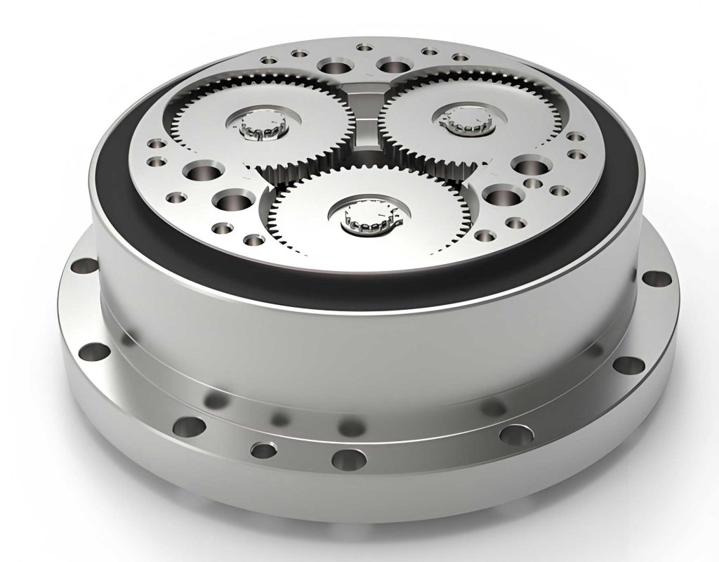
The fundamental operation of a rotary vector reducer revolves around its two-stage reduction system. The first stage involves a sun gear, planet gears, and a planet carrier, where input rotation from a motor drives the sun gear, which in turn engages with multiple planet gears. The planet gears are mounted on crankshafts that serve as the input to the second stage. In the second stage, the crankshafts drive cycloidal gears (also known as RV gears) that mesh with a stationary pin gear housing. The relative motion between the cycloidal gears and the pin teeth results in a further speed reduction, with the output taken from the planet carrier or the housing, depending on the configuration. This dual-stage setup allows the rotary vector reducer to achieve reduction ratios typically ranging from 30 to over 200, while maintaining high rigidity and efficiency. The intricate interplay between components demands precise alignment and optimization, particularly in gear tooth profiles and counts, to ensure smooth operation and longevity. Understanding this mechanism is crucial for developing accurate design algorithms, as any miscalculation can lead to performance degradation or mechanical failure. Thus, a thorough analysis of the reducer’s kinematics and dynamics forms the foundation for the automated design processes discussed herein.
To automate the gear calculation for a rotary vector reducer, several design conditions must be satisfied simultaneously. These conditions ensure that the reducer meets performance specifications while adhering to mechanical constraints. For this study, a specific model, the RV-110E reducer, is used as a reference, with an input power of 2.26 kW, output speed of 15 rpm, target reduction ratio of 111, and module of 1.25 mm. The gear calculation involves determining the number of teeth for the sun gear (\(Z_1\)), planet gears (\(Z_2\)), and pin teeth (\(Z_5\)), based on five key criteria. First, the transmission ratio condition ensures that the overall reduction ratio matches the desired value within a permissible error margin. The formula for the reduction ratio when the pin housing is fixed is given by:
$$ i = 1 + \frac{Z_2}{Z_1} \cdot Z_5 $$
where \(i\) is the actual reduction ratio. The allowable error is defined as:
$$ \left| \frac{i – i_p}{i_p} \right| \leq \Delta i_p $$
with \(i_p\) as the target ratio (e.g., 111) and \(\Delta i_p\) typically ranging from 0.01 to 0.04. Second, the non-undercut condition prevents gear tooth root cutting, which weakens the gear structure; this requires \(Z_1 \geq 17\) for standard involute gears. Third, the load distribution condition limits the torque input into the second stage by enforcing \(\frac{Z_2}{Z_1} \geq 1.5\), ensuring balanced load sharing among planet gears. Fourth, the one-tooth difference condition mandates that \(Z_5\) be an even number, as the cycloidal gear must have one less tooth than the pin teeth for proper meshing in the second stage. Fifth, the structural dimension condition relates the center distance between the sun and planet gears (\(a_0\)) to the pin gear circle radius (\(R_p\)), as expressed by:
$$ a_0 = (0.5 \sim 0.6) R_p $$
where \(R_p\) is derived from the output torque and efficiency considerations. The output torque \(T\) is calculated as:
$$ T = 9,550,000 \cdot \frac{P}{n} \cdot \eta $$
with \(P\) as power (kW), \(n\) as output speed (rpm), and \(\eta\) as overall efficiency. The efficiency \(\eta\) accounts for gear meshing and bearing losses, computed through:
$$ \eta = \eta_{16} \cdot \eta_B $$
where \(\eta_B\) is the combined bearing efficiency, and \(\eta_{16}\) represents the gear transmission efficiency, given by:
$$ \eta_{16} = \frac{\left( \frac{Z_5}{Z_4} – 1 \right) \left( \frac{Z_5}{Z_4} – \eta_{H6} \right) + \frac{Z_2}{Z_1} \cdot \frac{Z_5}{Z_4} \cdot \eta_{H1}}{\left( \frac{Z_5}{Z_4} – \eta_{H6} \right) \left( \frac{Z_5}{Z_4} – 1 \right) + \frac{Z_2}{Z_1} \cdot \frac{Z_5}{Z_4}} $$
Here, \(Z_4\) is the number of teeth on the cycloidal gear (where \(Z_4 = Z_5 – 1\)), \(\eta_{H1}\) is the meshing efficiency of the involute gears (typically 0.992), and \(\eta_{H6}\) is the meshing efficiency of the cycloidal stage (typically 0.998). These equations form a system of constraints that must be solved iteratively to find viable tooth combinations.
The automated gear calculation program was implemented using VB.NET within the Visual Studio 2022 environment. The algorithm begins by inputting the four key parameters: power \(P\), target reduction ratio \(i_p\), module \(m\), and output speed \(n\). It then iterates through possible values of \(Z_1\) and \(Z_2\), checking each against the five conditions. For each valid pair, \(Z_5\) is computed from the transmission ratio equation, and the structural condition is verified. The program outputs multiple sets of feasible tooth numbers, along with derived values such as actual reduction ratio and output torque. This approach not only accelerates the design process but also explores a wider design space, potentially uncovering optimal configurations that might be overlooked in manual calculations. The rotary vector reducer benefits greatly from such automation, as even minor adjustments in tooth counts can impact performance metrics like efficiency, noise, and load capacity. By encoding these constraints into a program, designers can rapidly evaluate hundreds of combinations, ensuring robustness and compliance with specifications.
The results from the gear calculation program for the RV-110E rotary vector reducer are summarized in the table below. Twenty-five distinct gear sets were generated, each satisfying all five design conditions. The table includes the sun gear teeth (\(Z_1\)), planet gear teeth (\(Z_2\)), pin teeth (\(Z_5\)), overall efficiency (\(\eta\)), output torque (\(T\)), and actual reduction ratio (\(i\)). These data points illustrate the trade-offs between different parameters; for instance, higher pin tooth counts tend to increase the reduction ratio but may affect structural dimensions. Based on considerations of transmission accuracy and load distribution, sets 3, 7, 10, 12, 13, 15, 20, 21, and 22 are identified as particularly favorable for the rotary vector reducer design, as they balance efficiency and torque characteristics effectively.
| Set | \(Z_1\) | \(Z_2\) | \(Z_5\) | \(\eta\) | \(T\) (N·m) | \(i\) |
|---|---|---|---|---|---|---|
| 1 | 17 | 59 | 32 | 0.907 | 1304.526 | 112.059 |
| 2 | 18 | 62 | 32 | 0.907 | 1304.532 | 111.222 |
| 3 | 19 | 62 | 34 | 0.903 | 1299.679 | 111.947 |
| 4 | 19 | 70 | 46 | 0.883 | 1270.952 | 170.474 |
| 5 | 20 | 55 | 40 | 0.892 | 1278.000 | 111.000 |
| 6 | 20 | 69 | 46 | 0.883 | 1271.001 | 159.700 |
| 7 | 21 | 68 | 34 | 0.903 | 1299.685 | 111.095 |
| 8 | 22 | 61 | 40 | 0.893 | 1285.350 | 111.909 |
| 9 | 22 | 72 | 34 | 0.903 | 1299.676 | 112.273 |
| 10 | 22 | 68 | 46 | 0.883 | 1271.092 | 143.182 |
| 11 | 23 | 75 | 34 | 0.903 | 1299.679 | 111.870 |
| 12 | 23 | 66 | 46 | 0.883 | 1271.159 | 133.000 |
| 13 | 24 | 58 | 46 | 0.884 | 1271.334 | 112.167 |
| 14 | 24 | 78 | 34 | 0.903 | 1299.682 | 111.500 |
| 15 | 24 | 65 | 46 | 0.883 | 1271.215 | 125.583 |
| 16 | 25 | 69 | 40 | 0.893 | 1285.355 | 111.400 |
| 17 | 25 | 81 | 34 | 0.903 | 1299.685 | 111.160 |
| 18 | 25 | 82 | 34 | 0.903 | 1299.674 | 112.520 |
| 19 | 25 | 70 | 46 | 0.883 | 1271.182 | 129.800 |
| 20 | 25 | 69 | 46 | 0.883 | 1271.196 | 127.960 |
| 21 | 25 | 68 | 46 | 0.883 | 1271.211 | 126.120 |
| 22 | 25 | 64 | 46 | 0.884 | 1271.272 | 118.760 |
| 23 | 26 | 84 | 34 | 0.903 | 1299.687 | 110.846 |
| 24 | 26 | 85 | 34 | 0.903 | 1299.677 | 112.154 |
| 25 | 27 | 65 | 46 | 0.884 | 1271.339 | 111.741 |
Following the gear calculation, it is essential to verify the mechanical strength of the gears to ensure reliability under operational loads. For the rotary vector reducer, the sun and planet gears are subjected to significant stresses, and their design must prevent failures such as tooth bending or surface pitting. Thus, a separate program was developed to perform strength calibration, focusing on tooth root bending fatigue strength and tooth surface contact fatigue strength. These calculations adhere to standard gear design principles, incorporating factors like load coefficients, material properties, and geometry. The program automates the evaluation process, allowing designers to quickly assess whether a given gear set meets safety margins. This step is critical because even if the tooth numbers satisfy kinematic conditions, inadequate strength could lead to premature failure, compromising the entire rotary vector reducer system.
For tooth root bending fatigue strength, the criterion is that the calculated bending stress (\(\sigma_F\)) must not exceed the allowable bending stress (\(\sigma_{FP}\)). The bending stress is computed using:
$$ \sigma_F = \frac{F_t}{b m} K_A K_V K_{F\beta} K_{F\alpha} K_{Fp} Y_{Fa} Y_{Sa} Y_{\epsilon} Y_{\beta} $$
where \(F_t\) is the nominal tangential force, \(b\) is the face width, \(m\) is the module, \(K_A\) is the application factor, \(K_V\) is the dynamic factor, \(K_{F\beta}\) is the face load distribution factor, \(K_{F\alpha}\) is the transverse load distribution factor, \(K_{Fp}\) is the planet load sharing factor, \(Y_{Fa}\) is the form factor, \(Y_{Sa}\) is the stress correction factor, \(Y_{\epsilon}\) is the contact ratio factor, and \(Y_{\beta}\) is the helix angle factor. The allowable bending stress is given by:
$$ \sigma_{FP} = \frac{\sigma_{F \lim}}{S_{F \min}} Y_{ST} Y_{NT} Y_{\delta relT} Y_{RrelT} Y_X $$
with \(\sigma_{F \lim}\) as the bending endurance limit, \(S_{F \min}\) as the minimum safety factor, \(Y_{ST}\) as the stress correction factor, \(Y_{NT}\) as the life factor, \(Y_{\delta relT}\) as the relative notch sensitivity factor, \(Y_{RrelT}\) as the relative surface condition factor, and \(Y_X\) as the size factor. These factors account for material characteristics, loading conditions, and manufacturing quality, ensuring a comprehensive strength assessment for the rotary vector reducer gears.
For tooth surface contact fatigue strength, the condition is that the calculated contact stress (\(\sigma_H\)) must be less than the allowable contact stress (\(\sigma_{HP}\)). The contact stress formula is:
$$ \sigma_H = Z_H Z_E Z_{\epsilon} Z_{\beta} \sqrt{\frac{F_t}{d b} \cdot \frac{\mu \pm 1}{\mu} K_A K_V K_{H\beta} K_{H\alpha} K_{Hp}} $$
where \(Z_H\) is the zone factor, \(Z_E\) is the elasticity factor, \(Z_{\epsilon}\) is the contact ratio factor, \(Z_{\beta}\) is the helix angle factor, \(d\) is the pitch diameter, \(\mu\) is the gear ratio (\(Z_2 / Z_1\) for sun-planet mesh), and \(K_{H\beta}\), \(K_{H\alpha}\), and \(K_{Hp}\) are load factors analogous to those in bending calculations. The allowable contact stress is expressed as:
$$ \sigma_{HP} = \frac{\sigma_{H \lim}}{S_{H \min}} Z_{NT} Z_L Z_V Z_R Z_W Z_X $$
with \(\sigma_{H \lim}\) as the contact endurance limit, \(S_{H \min}\) as the minimum safety factor, \(Z_{NT}\) as the life factor, \(Z_L\) as the lubricant factor, \(Z_V\) as the velocity factor, \(Z_R\) as the roughness factor, \(Z_W\) as the work hardening factor, and \(Z_X\) as the size factor. These equations encapsulate the complex interactions between gear geometry, material properties, and operational environment, providing a robust framework for evaluating the durability of the rotary vector reducer components.
The strength calibration program was also implemented in VB.NET, integrating with the gear calculation output. For illustration, consider gear set 5 from the table, with \(Z_1 = 20\), \(Z_2 = 55\), and \(Z_5 = 40\). Using the module \(m = 1.25\) mm and other design parameters (e.g., face width derived from standard proportions, material grade of case-hardened steel), the program computes the bending and contact stresses. The results indicate that both stresses are well within allowable limits, confirming the suitability of this gear set for the rotary vector reducer. The program outputs detailed reports, including intermediate factors and safety margins, which aid in fine-tuning the design. For instance, the bending stress calculation might reveal that increasing the face width slightly could further reduce stress concentrations, enhancing the reducer’s lifespan. This iterative capability is invaluable for optimizing the rotary vector reducer, as it allows designers to balance strength, weight, and cost effectively.
Beyond individual gear sets, the program facilitates comparative analysis across multiple configurations. By running strength checks on all 25 gear sets, designers can identify trends—for example, how pin tooth count influences contact stress or how sun gear size affects bending stress. This holistic view supports informed decision-making, ensuring that the selected design not only meets basic criteria but also excels in performance metrics. The rotary vector reducer, being a high-precision device, benefits from such rigorous validation, as even minor stress variations can impact reliability in demanding applications like industrial robotics. Moreover, the automation reduces human error, as manual calculations of these complex formulas are prone to mistakes, especially when dealing with numerous coefficients and interdependencies.
The integration of gear calculation and strength calibration into a unified workflow represents a significant advancement for rotary vector reducer design. Traditionally, these tasks were performed sequentially by different engineers, often leading to delays and inconsistencies. With the automated programs, the entire process from initial parameters to final verification can be completed in minutes, rather than days or weeks. This acceleration is crucial in competitive industries where time-to-market is a key factor. Furthermore, the programs are adaptable; by modifying input parameters, they can be applied to other rotary vector reducer models or even custom designs, enhancing their versatility. The use of VB.NET and Visual Studio ensures accessibility, as these tools are widely used in engineering domains, and the code can be easily modified or extended to include additional features, such as thermal analysis or vibration assessment.
In terms of practical implementation, the programs feature user-friendly interfaces with input fields for key parameters and output displays in tabular and graphical formats. For the gear calculation, users can specify ranges for tooth numbers or efficiency thresholds, allowing for targeted exploration. For strength calibration, material databases can be incorporated to automate factor selection based on gear grade. These enhancements make the tools not just computational aids but comprehensive design assistants for the rotary vector reducer. Additionally, the programs generate exportable reports in formats like Excel, facilitating documentation and collaboration among design teams. This seamless integration into existing workflows underscores the practical value of parameterizing design steps for complex mechanical systems like the rotary vector reducer.
Looking forward, further refinements could include optimization algorithms to automatically select the best gear set based on multi-objective criteria, such as minimizing weight while maximizing efficiency. Machine learning techniques might also be employed to predict performance based on historical data, reducing the need for exhaustive calculations. However, even in its current state, the automated approach demonstrates substantial benefits for rotary vector reducer development. By reducing manual effort and increasing accuracy, it empowers engineers to focus on higher-level design challenges, such as innovation in materials or topology. This shift towards computational design is emblematic of broader trends in mechanical engineering, where digital tools are becoming indispensable for handling complexity.
In conclusion, the automated gear calculation and strength calibration programs presented here offer a robust solution for streamlining the design of rotary vector reducers. By encoding the essential conditions and formulas into software, they enable rapid generation and validation of gear configurations, ensuring compliance with performance and safety standards. The results from the RV-110E case study confirm the feasibility of this approach, with multiple viable gear sets identified and verified through strength analysis. This methodology not only shortens design cycles but also enhances the reliability and optimization of rotary vector reducers, contributing to their effective deployment in precision applications. As industrial robotics continues to evolve, such automated design tools will play an increasingly vital role in advancing mechanical systems, and the rotary vector reducer stands to gain significantly from these innovations.