
In the field of mobile robotics, legged platforms such as the robot dog have demonstrated exceptional versatility in navigating complex, unstructured environments. Traditional gait planning methods, often based on pre-defined trajectories, result in motions that are rigid, slow, and lack the adaptive, self-organizing capabilities observed in biological organisms. This disconnect between engineered and natural locomotion has motivated my research into biologically inspired control strategies. Specifically, I have focused on developing a gait control system for a four-legged robot dog centered on the concept of Central Pattern Generators (CPGs). CPGs are neural circuits found in vertebrates that autonomously produce rhythmic signals for coordinated movements like walking, without needing continuous sensory feedback. By emulating this biological mechanism, my goal is to enable the robot dog to achieve more fluid, robust, and adaptive locomotion.
The core of my approach lies in constructing a CPG model composed of interconnected nonlinear oscillators. Each oscillator unit represents a simplified neuron and is responsible for generating the rhythmic signals that drive the joints of the robot dog. The mathematical model for a single neuron is defined as follows:
$$ T_r \frac{du_i}{dt} + u_i = -\sum_{j=1}^{n} w_{ij} y_j + w_0 s_i – b v_i + Feed_i $$
$$ T_a \frac{dv_i}{dt} + v_i = y_i $$
$$ y_i = g(u_i – \theta) = max(0, u_i – \theta) $$
In this formulation, \( u_i \) represents the membrane potential of neuron \( i \), \( y_i \) is its output, and \( v_i \) denotes its fatigue or adaptation level. The parameters \( T_r \) and \( T_a \) are time constants governing the rise time and adaptation delay, respectively. The term \( w_{ij} \) represents the inhibitory synaptic weight from neuron \( j \) to neuron \( i \), which is crucial for establishing the coupling relationships between oscillators. \( s_i \) is a constant or slowly varying external stimulus, \( b \) is a constant influencing the steady-state firing rate, and \( \theta \) is the output threshold. The \( Feed_i \) term is particularly important as it incorporates sensory feedback from the robot dog’s environment, such as ground contact forces, allowing the CPG network to dynamically adjust its output in response to external perturbations. This closed-loop architecture enables the robot dog’s control system to exhibit self-organizing properties.
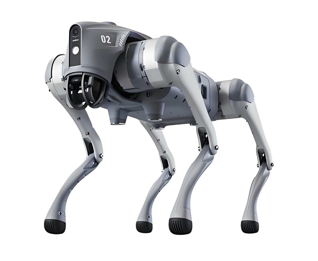
To realize this control strategy, I designed a physical quadruped robot dog platform. Each leg of the robot dog features two degrees of freedom: a hip joint and a knee joint, allowing motion in a single sagittal plane. Servo motors were selected as the joint actuators due to their precision and ease of control. The mechanical dimensions are critical for gait stability; the upper leg link (\( L_1 \)) and lower leg link (\( L_2 \)) were set to 65mm and 200mm, respectively. The entire chassis was constructed using a lightweight aluminum alloy frame. For environmental interaction, each foot of the robot dog is equipped with a pressure sensor to detect ground contact and terrain properties. Furthermore, the head of the robot dog houses a servo-mounted photoelectric reflective sensor, enabling obstacle detection within a 180-degree arc up to 75cm away. This sensor suite provides the necessary \( Feed_i \) inputs to the CPG network, allowing the robot dog to sense and adapt to its surroundings.
The CPG network’s control mechanism for the robot dog involves coordinating multiple oscillators to produce stable gait patterns. The network architecture for a single leg’s joint control is illustrated conceptually, where rhythm-generating neurons interact with flexor and extensor motor neurons. These interactions, governed by specific connection weight matrices \( w_{ij} \), produce the alternating activation patterns required for swing and stance phases. By configuring different weight matrices, the same CPG network can generate various typical quadruped gaits such as walk, trot, and pace for the robot dog. The relationship between the robot dog’s limb segments is governed by kinematic constraints. Defining the coordinates and joint angles as per a standard model, the position of the hip joint relative to the ankle (or foot contact point) can be expressed as:
$$ x_{ih} = x_{ia} – l_2 \sin(h_2 + k_2) – l_3 \sin h_2 $$
$$ z_{ih} = z_{ia} + l_2 \cos(h_2 + k_2) + l_3 \cos h_2 $$
Here, \( i \) denotes either the left (\( l \)) or right (\( r \)) leg of the robot dog. \( (x_{ih}, z_{ih}) \) and \( (x_{ia}, z_{ia}) \) are the hip and ankle coordinates in the X-Z plane, respectively. \( l_2 \) and \( l_3 \) are the lengths of the lower and upper leg links (corresponding to \( L_2 \) and \( L_1 \) mentioned earlier), and \( h_2 \) and \( k_2 \) are the joint angles for the hip and knee (rotation about the Y-axis), with zero defined at the standing position and positive in the counterclockwise direction. To derive joint velocities, I differentiated these equations with respect to time:
$$ \dot{x}_{ih} = \dot{x}_{ia} – l_2 (\dot{h}_2 + \dot{k}_2) \cos(h_2 + k_2) – l_3 \dot{h}_2 \cos h_2 $$
$$ \dot{z}_{ih} = \dot{z}_{ia} – l_2 (\dot{h}_2 + \dot{k}_2) \sin(h_2 + k_2) – l_3 \dot{h}_2 \sin h_2 $$
Solving this system for the joint angular velocities \( \dot{h}_2 \) and \( \dot{k}_2 \) yields the following expressions, which are essential for converting desired foot trajectories into joint motor commands for the robot dog:
$$ \dot{h}_2 = \frac{(\dot{z}_{ih} – \dot{z}_{ia}) \cos(h_2 + k_2) – (\dot{x}_{ih} – \dot{x}_{ia}) \sin(h_2 + k_2)}{l_3 \sin k_2} $$
$$ \dot{k}_2 = \frac{(\dot{x}_{ih} – \dot{x}_{ia})[l_2 \sin(h_2 + k_2) + l_3 \sin h_2]}{l_2 l_3 \sin k_2} – \frac{(\dot{z}_{ih} – \dot{z}_{ia})[l_2 \cos(h_2 + k_2) + l_3 \cos h_2]}{l_2 l_3 \sin k_2} $$
To manage the complexity of multi-joint coordination, I summarize the key parameters and relationships of the CPG-based control system for the robot dog in the following table:
| Component | Parameter/Symbol | Description | Typical Value/Role |
|---|---|---|---|
| CPG Neuron | \( u_i \) | Membrane potential | State variable |
| \( y_i \) | Neuron output | Oscillatory signal | |
| \( T_r, T_a \) | Time constants | Govern dynamics (e.g., 0.1s, 0.5s) | |
| \( w_{ij} \) | Synaptic weight | Defines coupling between neurons | |
| \( Feed_i \) | Sensory feedback | Input from robot dog’s sensors | |
| \( \theta \) | Output threshold | Determines activation (e.g., 0.05) | |
| Robot Dog Leg | \( l_2, l_3 \) | Link lengths | 200mm, 65mm |
| \( h_2, k_2 \) | Hip & knee angles | Controlled variables | |
| DOF per leg | Degrees of freedom | 2 (hip & knee) | |
| Actuator | Joint driver | Servo motor | |
| Gait Parameters | \( \lambda \) | Stride length | 40 mm (example) |
| \( H \) | Swing leg height | 20 mm (example) | |
| Gait type | Pattern | Determined by CPG weights \( w_{ij} \) |
The hardware implementation of the robot dog was designed with a clear separation between the low-level joint drivers and the high-level CPG gait algorithm platform. This modular approach enhances flexibility for sensor integration and algorithm updates. The low-level driver is a custom-designed 16-channel servo controller. Since servos operate by comparing an internal potentiometer’s feedback to an input pulse-width modulation (PWM) signal, my driver circuit uses an ATmega8 microcontroller to generate precisely timed PWM signals for all 16 servos simultaneously. The core mechanism involves using the microcontroller’s 16-bit timer to generate timed interrupts. During each interrupt service routine, a shift pulse is produced and sent through opto-isolators (like 4N25) to shift registers, which sequentially generate the high-phase of the PWM signal for each servo channel. This design ensures accurate and synchronized control of all joint actuators in the robot dog.
The high-level algorithm platform, also centered on an ATmega8 microcontroller, hosts the CPG gait generation algorithm. This platform stores pre-calculated gait parameters or runs the CPG differential equations in real-time. It reads sensor data from the robot dog’s feet and head, processes this information to compute the \( Feed_i \) terms, and then updates the joint angle setpoints. These setpoints are transmitted in real-time via a UART interface to the low-level servo driver. This hierarchical control structure allows the robot dog to perform complex, adaptive locomotion based on the CPG model’s outputs. The table below summarizes the key hardware modules of the robot dog system:
| Hardware Module | Core Component | Primary Function |
|---|---|---|
| High-Level Controller | ATmega8 Microcontroller | Executes CPG algorithm, processes sensor data, sends joint commands. |
| Low-Level Servo Driver | ATmega8, Shift Registers, Opto-isolators | Generates 16 synchronized PWM signals to control all servos. |
| Actuation System | 16x Servo Motors | Drives hip and knee joints of the four-legged robot dog. |
| Proprioceptive Sensing | 4x Foot Pressure Sensors | Provides ground contact feedback (\( Feed_i \)) to the CPG. |
| Exteroceptive Sensing | Head-mounted Photoelectric Sensor | Detects obstacles for navigation and gait adjustment. |
| Power System | Li-Po Battery, Regulators | Supplies power to all electronics and actuators of the robot dog. |
To validate the CPG-based control strategy before physical deployment, I conducted extensive simulations in MATLAB. The simulation aimed to derive optimal foot trajectories and verify the stability of the generated gaits for the robot dog. For a smooth walking motion, I set parameters such as a stride length \( \lambda = 40 \) mm and a maximum swing leg lift \( H = 20 \) mm. The trajectory of the ankle (or foot) during the swing phase was designed as a smooth polynomial function to ensure stable motion for the robot dog. Based on the kinematic constraints, the ankle’s vertical position \( y \) as a function of its horizontal position \( x \) during a swing phase can be described by a cubic spline. For instance, a symmetric trajectory can be defined piecewise:
$$ f(x) = -\frac{20}{8 \times 10^2}(2x^3 + 60x^2 – 8 \times 10^3), \quad x \in [-20, 0] $$
$$ f(x) = -\frac{20}{8 \times 10^2}(-2x^3 + 60x^2 – 8 \times 10^3), \quad x \in [0, 20] $$
Here, \( x \) and \( y = f(x) \) are in millimeters, representing the foot position relative to the hip during the swing. To express this as a function of time \( t \) over a stride period \( T \), I parameterized the horizontal motion: \( x(t) = \frac{t}{T} \lambda – \frac{\lambda}{2} \), and consequently \( y(t) = f(x(t)) \). The hip joint’s trajectory during the support phase was simplified to a horizontal movement to propel the robot dog’s body forward: \( x_2(t) = \frac{\lambda}{2T} t \), with a constant height \( y_2 = H_k \), where \( H_k \) is the nominal hip height.
By feeding these reference trajectories into the CPG network model and solving the coupled differential equations, I simulated the complete locomotion cycle of the robot dog. The CPG network successfully generated stable, periodic signals that drove the joint angles according to the kinematic equations. A key output of the simulation was the analysis of the robot dog’s stability. For a quadruped, stability is often assessed via the concept of the support polygon and the projection of the center of mass. My simulation calculated the reachable workspace of the body’s center in the global coordinate frame under different support polygon configurations (e.g., three feet on the ground during a trot). The results, illustrated in a plot, showed a continuous and sizable reachable workspace, indicating that the CPG-generated gaits for the robot dog provide inherent stability and adaptability to small disturbances. The simulation confirmed that the CPG control strategy effectively manages the nonlinearities and coupling inherent in multi-joint systems, producing smooth and plausible gait patterns for the robot dog.
The mathematical foundation of the CPG model allows for in-depth analysis of its oscillatory properties. The dynamics of a network of such neurons can be studied by examining the system’s eigenvalues and phase relationships. For a minimal network controlling one joint with flexor and extensor neurons, the equations can be linearized around an operating point to understand the conditions for oscillation. The characteristic equation involves parameters like \( T_r, T_a, \) and \( w_{ij} \). For instance, the condition for a Hopf bifurcation, which gives rise to stable limit cycles, can be derived. This analysis is crucial for tuning the robot dog’s CPG parameters to achieve desired oscillation frequencies and amplitudes. The relationship between the CPG output frequency \( f_{CPG} \) and the robot dog’s stepping frequency \( f_{step} \) is direct: \( f_{step} = f_{CPG} \). Therefore, by adjusting the time constants and weights in the model, I can control the walking speed of the robot dog. The following table summarizes the influence of key CPG parameters on the robot dog’s gait characteristics:
| CPG Parameter | Effect on Oscillation | Result on Robot Dog Gait |
|---|---|---|
| Increased \( T_r \) | Slower rise time of \( u_i \) | Slower, more gradual joint movements. |
| Increased \( T_a \) | Slower adaptation (fatigue) | Longer stride duration, reduced high-frequency jitter. |
| Increased \( |w_{ij}| \) (Inhibition) | Stronger neuron coupling | More stable phase-locking between legs, robust gait. |
| Increased \( w_0 s_i \) (Stimulus) | Higher baseline excitation | Increased oscillation amplitude, larger joint angles. |
| Increased \( Feed_i \) gain | Stronger sensory feedback | Faster terrain adaptation, but potential instability if too high. |
Transitioning between different gaits, such as from a walk to a trot, is a significant advantage of the CPG approach for the robot dog. This can be achieved by dynamically modulating the connection weights \( w_{ij} \) between the oscillators representing different legs. For example, in a walk gait, the phase difference between successive legs is 90 degrees. In a trot, diagonal leg pairs are in phase, with a 180-degree difference between the front-left/right-hind pair and the front-right/left-hind pair. This can be encoded in the weight matrix \( W = [w_{ij}] \). Let the oscillator indices 1,2,3,4 represent the left-front, right-front, left-hind, and right-hind hip joint controllers, respectively. A simplified weight matrix to induce a trot pattern might have strong inhibitory connections between oscillators 1 & 4 and 2 & 3 (diagonal pairs in phase), and weaker or different connections for others. The process of online gait transition for the robot dog involves smoothly varying these weights based on a speed command or terrain assessment from the sensors.
The hardware design also involved careful consideration of power management and real-time performance for the robot dog. The servo motors, especially under load, draw significant current. The power distribution network was designed to prevent voltage drops that could cause microcontroller resets or erratic servo behavior. The control loops run at different rates: the high-level CPG algorithm updates at a lower frequency (e.g., 50-100 Hz), sufficient for gait generation, while the low-level servo PWM signals require a consistent 50 Hz refresh rate. The ATmega8 microcontrollers, while limited in computational power, were adequate for these tasks when programmed efficiently in C. The communication protocol between the high-level and low-level controllers used a simple packet structure containing target positions for all 8 joints (2 joints/leg * 4 legs) of the robot dog.
In conclusion, the application of Central Pattern Generator models presents a powerful and biologically inspired solution for gait control in legged robots, specifically the robot dog. My research has demonstrated that a CPG-based control strategy can effectively address the challenges of joint trajectory tracking, including nonlinear dynamics, coupling effects, and the need for real-time adaptation. By designing a coupled oscillator network that incorporates sensory feedback, the robot dog achieves locomotion that is not only stable and coordinated but also possesses inherent self-organizing capabilities to cope with uneven terrain and disturbances. The hardware and software architecture developed for the robot dog successfully implements this concept, separating gait generation from low-level actuation for flexibility. Simulations have confirmed the viability of the approach, showing stable limit cycles and adaptable gait patterns. This work lays a foundation for more advanced bio-inspired control systems in robotics, moving beyond pre-computed trajectories towards adaptive, emergent locomotion. Future work will focus on implementing more complex CPG networks for dynamic gait transitions, integrating higher-level learning algorithms to optimize CPG parameters online, and testing the physical robot dog platform across a wider variety of real-world terrains to fully exploit its adaptive potential.
The mathematical elegance of the CPG model allows for further extensions. For instance, the basic neuron model can be made more biologically plausible by adding features like spike-frequency adaptation or different neurotransmitter dynamics. However, for engineering purposes, the model I used offers a good balance between complexity and computational tractability for the robot dog. The fundamental equation set forms a system of nonlinear ordinary differential equations (ODEs):
$$ \frac{d\mathbf{U}}{dt} = \mathbf{T}_r^{-1} ( -\mathbf{U} – \mathbf{W} \cdot \mathbf{Y} + \mathbf{w}_0 \mathbf{s} – b \mathbf{V} + \mathbf{Feed} ) $$
$$ \frac{d\mathbf{V}}{dt} = \mathbf{T}_a^{-1} ( \mathbf{Y} – \mathbf{V} ) $$
$$ \mathbf{Y} = g(\mathbf{U} – \theta) $$
where \( \mathbf{U}, \mathbf{V}, \mathbf{Y} \) are vectors of neuron states, \( \mathbf{T}_r \) and \( \mathbf{T}_a \) are diagonal matrices of time constants, \( \mathbf{W} \) is the connection weight matrix, and \( \mathbf{Feed} \) is the feedback vector. The stability of the synchronized oscillatory solution for the robot dog’s gait can be analyzed using master stability function techniques or by examining phase response curves. This deeper theoretical understanding will guide the design of even more robust and agile locomotion for future generations of the robot dog. The journey to create a truly biomimetic robot dog is ongoing, but CPG-based control represents a significant stride toward that goal, blending insights from neuroscience with the precision of engineering to create machines that move with the grace and adaptability of living creatures.