
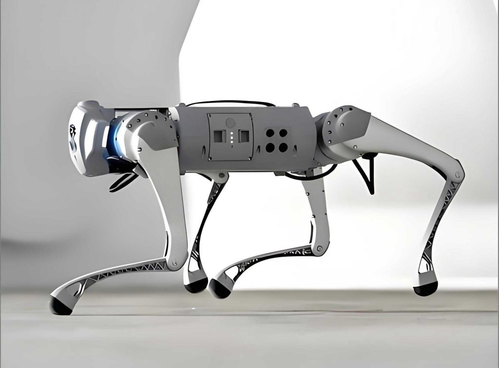
As an enthusiast in electronics and robotics, I have always been fascinated by the charm and functionality of intelligent robot dogs. Their adorable appearance and multi-sensory capabilities make them not only engaging companions but also excellent educational projects that inspire hands-on learning. In this article, I will share my detailed experience in constructing a robot dog from scratch, focusing on the system architecture, working principles, printed circuit board (PCB) fabrication, component installation, soldering techniques, and system assembly and debugging. This guide aims to provide comprehensive insights for hobbyists and students interested in creating their own robot dog, emphasizing practical skills and theoretical understanding. Throughout this discussion, the term ‘robot dog’ will be frequently referenced to highlight its core role in this project.
The robot dog I built features sound, light, and magnetic control characteristics. When external stimuli such as clapping sounds, a magnet brought near its tail, or a flashlight shone on its belly are applied, the robot dog automatically walks for a distance before stopping. Upon subsequent triggers, it repeats this process. This interactive behavior makes the robot dog an ideal platform for exploring sensor integration and control systems. Below, I will delve into each aspect of the construction process, incorporating tables and formulas to summarize key concepts.
To understand the robot dog’s operation, we must first analyze its circuit design. The core of the circuit is a monostable multivibrator built around a 555 timer, which governs the effectiveness of the sound, light, and magnetic controls. I will begin by explaining the workings of the 555 timer-based monostable trigger, as it is fundamental to the robot dog’s functionality.
The 555 timer is an integrated circuit with eight pins, each serving specific functions. Its internal structure can be represented with key parameters summarized in the following table:
| Pin Number | Symbol | Function |
|---|---|---|
| 1 | GND | Ground connection |
| 2 | TRIG | Low-level trigger input |
| 3 | OUT | Output |
| 4 | RESET | Reset (active low) |
| 5 | CONT | Control voltage |
| 6 | THRES | High-level trigger input |
| 7 | DISCH | Discharge |
| 8 | VCC | Power supply |
The functionality of the 555 timer is defined by its truth table, which dictates output states based on input conditions. For the robot dog circuit, we focus on the monostable mode, where the output produces a single pulse of defined duration upon trigger. The monostable configuration uses external resistors and capacitors to set the pulse width. The output pulse width (t_w) is given by the formula:
$$t_w \approx 1.1 R C$$
Here, R and C are the timing resistor and capacitor, respectively. This formula is critical for designing the robot dog’s walking duration, as it determines how long the motor remains active after a trigger event.
In the robot dog circuit, the monostable trigger is integrated with three sensor modules: sound control via a microphone, light control via an infrared receiver, and magnetic control via a reed switch. The overall circuit composition includes these sensors, an AC small-signal amplifier, a pulse generation circuit, the monostable circuit, a motor drive circuit, and power supply components. Below is a table summarizing the key components and their roles in the robot dog:
| Component | Symbol | Function in Robot Dog |
|---|---|---|
| Microphone | S1 | Sound sensor converting acoustic signals to electrical signals |
| Infrared Receiver | S2 | Light sensor responding to infrared illumination |
| Reed Switch | S3 | Magnetic sensor activating with magnetic proximity |
| 555 Timer | IC1 | Core IC forming monostable trigger for control logic |
| Transistor Q2 | Q2 | Part of pulse generation circuit triggering monostable |
| Motor M1 | M1 | DC motor driving robot dog movement |
| Resistor R6 | R6 | Timing resistor setting pulse width with C5 |
| Capacitor C5 | C5 | Timing capacitor setting pulse width with R6 |
The working principle of the robot dog involves three control modes. In sound control, when the microphone detects a clap, it outputs a weak AC signal amplified by a transistor-based amplifier. This signal triggers the monostable circuit via the pulse generation circuit, causing the output to go high and activate the motor drive circuit. The motor then powers the robot dog to walk. The walking duration is precisely controlled by the monostable’s pulse width, calculated using the formula above. Similarly, for light control, the infrared receiver’s resistance decreases under light exposure, pulling the trigger pin low to initiate the sequence. In magnetic control, the reed switch closes when a magnet approaches, directly triggering the monostable. Each mode ensures the robot dog responds autonomously to environmental stimuli, making it an interactive and intelligent device.
To further elucidate the circuit behavior, let’s derive the transfer function for the amplifier stage. The AC small-signal amplifier uses a common-emitter configuration with transistor Q1. The voltage gain (A_v) can be approximated by:
$$A_v \approx -\frac{R_c}{r_e + R_e}$$
where R_c is the collector resistor, R_e is the emitter resistor, and r_e is the dynamic emitter resistance given by $$r_e = \frac{V_T}{I_E}$$, with V_T as the thermal voltage (approximately 26 mV at room temperature) and I_E as the emitter current. This amplification is crucial for boosting the microphone’s weak signal to a level sufficient to trigger the subsequent stages in the robot dog circuit.
Moving to the fabrication phase, I opted to make the PCB using the heat transfer method, which is accessible for DIY enthusiasts. The process involves designing the circuit layout, printing it on special paper, transferring the design onto copper-clad board via heat, etching away unwanted copper, and finally drilling holes for components. The steps are summarized in the table below:
| Step | Description | Key Considerations |
|---|---|---|
| 1. Design Layout | Use PCB design software to create trace layout | Ensure proper spacing and component placement for robot dog |
| 2. Print Design | Print mirrored layout on heat transfer paper | Use laser printer for best results |
| 3. Transfer | Apply heat to transfer toner onto copper board | Uniform pressure and temperature are critical |
| 4. Etching | Immerse board in ferric chloride to remove excess copper | Safety gear required; monitor etching time |
| 5. Drilling | Drill holes for component leads | Use appropriate drill bit sizes for robot dog components |
| 6. Cleaning | Clean board to remove residual toner and chemicals | Ensures good solderability for robot dog assembly |
After PCB fabrication, I proceeded with component installation. Prior to soldering, every component must be tested to ensure functionality and correct values. This pre-installation testing is vital for the robot dog’s reliability. The following table outlines the testing procedures for key components:
| Component Type | Test Method | Expected Result for Robot Dog |
|---|---|---|
| Resistors | Measure resistance with multimeter | Value within tolerance (e.g., ±5%) |
| Diodes | Check forward and reverse bias with multimeter | Forward conduction (~0.7V drop), reverse blocking |
| Transistors (NPN) | Test beta (β) using transistor tester | β > 200 for amplification in robot dog circuit |
| Electrolytic Capacitors | Check for leakage and polarity | Negligible leakage current; correct polarity marking |
| Infrared Receiver | Expose to light; measure resistance | Resistance drops significantly under illumination |
| Reed Switch | Bring magnet close; check continuity | Closes (continuity) when magnet is near |
| Microphone | Blow into it; observe resistance change | Resistance varies with sound input |
During installation, I employed a horizontal mounting style to save space, ensuring that diodes, transistors, and electrolytic capacitors were oriented correctly. Soldering was done in order of increasing component height, with care to avoid cold joints, bridges, or shorts. For instance, resistors and diodes were soldered first, followed by transistors and larger capacitors. This systematic approach minimized errors in the robot dog assembly.
The robot dog’s assembly involves integrating the PCB with mechanical parts, motors, and sensors. I disconnected the motor’s negative lead from the battery and rerouted it to the PCB’s motor negative terminal (M-), while connecting the motor positive (M+) to the PCB via a wire labeled J1. The power supply connections were made from the PCB’s V- and V+ to the battery, with V+ linked to M+ for simplicity. For magnetic control, wires from the PCB’s R+ and R- were soldered to the reed switch and placed near the robot dog’s tail. The infrared receiver was connected to I+ and I- on the PCB, with its longer leg attached to I-, and mounted on the belly through a drilled hole. The microphone was attached using shielded wire to reduce noise, with the center conductor as positive and the shield as negative, ensuring polarity alignment for optimal performance in the robot dog.
Debugging the robot dog required thorough checks before power-on. I measured for shorts between V- and V+ on the PCB to prevent damage. After assembly, functional tests were conducted for each control mode. The sound control test involved clapping to trigger walking; light control used a flashlight; and magnetic control employed a magnet. Each test verified that the robot dog walked for the duration set by the monostable pulse width, then stopped. The pulse width can be adjusted by changing R6 or C5 values, according to the formula $$t_w \approx 1.1 R_6 C_5$$. For example, with R6 = 100 kΩ and C5 = 100 μF, the walking time is approximately:
$$t_w \approx 1.1 \times 100 \times 10^3 \times 100 \times 10^{-6} = 11 \text{ seconds}$$
This flexibility allows customization of the robot dog’s behavior based on user preference.
Throughout the construction, I encountered challenges such as ensuring stable motor operation and minimizing false triggers. To address this, I added a feedback circuit involving diode D2 and transistor Q3, which helps maintain the monostable state during walking. The feedback mechanism ensures that once triggered, the robot dog completes its walking cycle without interruption. This enhancement improved the reliability of the robot dog, making it more responsive to sensory inputs.
In terms of educational value, building this robot dog has been immensely rewarding. It reinforces concepts in analog electronics, sensor technology, and embedded systems. The hands-on process cultivates problem-solving skills, as one must troubleshoot issues like poor solder joints or incorrect component placements. For instance, if the robot dog fails to walk, checking the monostable trigger voltage with an oscilloscope can reveal whether the 555 timer is receiving proper signals. The experience underscores the importance of precision in electronics, which is essential for developing robust robotic systems.
To further explore the theoretical aspects, let’s consider the noise immunity of the robot dog’s sensor circuits. The sound amplifier includes a coupling capacitor C1 to block DC and pass AC signals. Its cutoff frequency (f_c) is determined by:
$$f_c = \frac{1}{2\pi R C}$$
where R is the input resistance and C is the coupling capacitance. For the robot dog, with R4 = 10 kΩ and C1 = 0.1 μF, the cutoff frequency is approximately 159 Hz, effectively filtering out low-frequency noise while allowing voice frequencies to pass. Similarly, the infrared receiver circuit uses a voltage divider to set the trigger threshold, enhancing light sensitivity for the robot dog.
In conclusion, constructing an intelligent robot dog is a comprehensive project that blends theory with practice. From circuit design to final调试, every step offers learning opportunities in electronics and robotics. The robot dog serves as a tangible demonstration of how simple components can create interactive behavior. By following this guide, enthusiasts can build their own robot dog, gaining skills that extend to more advanced robotic projects. The repeated emphasis on the robot dog throughout this article highlights its central role in fostering innovation and technical proficiency. As robotics continues to evolve, such foundational projects remain invaluable for inspiring future engineers and hobbyists alike.